EP1925599B1 - Method of preparing core rods for optical fiber preforms - Google Patents
Method of preparing core rods for optical fiber preforms Download PDFInfo
- Publication number
- EP1925599B1 EP1925599B1 EP06024170A EP06024170A EP1925599B1 EP 1925599 B1 EP1925599 B1 EP 1925599B1 EP 06024170 A EP06024170 A EP 06024170A EP 06024170 A EP06024170 A EP 06024170A EP 1925599 B1 EP1925599 B1 EP 1925599B1
- Authority
- EP
- European Patent Office
- Prior art keywords
- sleeve
- sleeves
- core rods
- components
- entrance
- Prior art date
- Legal status (The legal status is an assumption and is not a legal conclusion. Google has not performed a legal analysis and makes no representation as to the accuracy of the status listed.)
- Ceased
Links
Images




Classifications
-
- B—PERFORMING OPERATIONS; TRANSPORTING
- B08—CLEANING
- B08B—CLEANING IN GENERAL; PREVENTION OF FOULING IN GENERAL
- B08B3/00—Cleaning by methods involving the use or presence of liquid or steam
- B08B3/04—Cleaning involving contact with liquid
-
- C—CHEMISTRY; METALLURGY
- C03—GLASS; MINERAL OR SLAG WOOL
- C03B—MANUFACTURE, SHAPING, OR SUPPLEMENTARY PROCESSES
- C03B37/00—Manufacture or treatment of flakes, fibres, or filaments from softened glass, minerals, or slags
- C03B37/01—Manufacture of glass fibres or filaments
- C03B37/012—Manufacture of preforms for drawing fibres or filaments
- C03B37/01205—Manufacture of preforms for drawing fibres or filaments starting from tubes, rods, fibres or filaments
-
- B—PERFORMING OPERATIONS; TRANSPORTING
- B08—CLEANING
- B08B—CLEANING IN GENERAL; PREVENTION OF FOULING IN GENERAL
- B08B2240/00—Type of materials or objects being cleaned
- B08B2240/02—Optical fibers or optical fiber connectors
-
- Y—GENERAL TAGGING OF NEW TECHNOLOGICAL DEVELOPMENTS; GENERAL TAGGING OF CROSS-SECTIONAL TECHNOLOGIES SPANNING OVER SEVERAL SECTIONS OF THE IPC; TECHNICAL SUBJECTS COVERED BY FORMER USPC CROSS-REFERENCE ART COLLECTIONS [XRACs] AND DIGESTS
- Y02—TECHNOLOGIES OR APPLICATIONS FOR MITIGATION OR ADAPTATION AGAINST CLIMATE CHANGE
- Y02P—CLIMATE CHANGE MITIGATION TECHNOLOGIES IN THE PRODUCTION OR PROCESSING OF GOODS
- Y02P40/00—Technologies relating to the processing of minerals
- Y02P40/50—Glass production, e.g. reusing waste heat during processing or shaping
- Y02P40/57—Improving the yield, e-g- reduction of reject rates
Definitions
- This invention concerns the production of glass preforms for optical fibers, particularly preforms of the rod-in-tube (RIT) variety.
- RIT rod-in-tube
- Initial stages of RIT fiber preform manufacture include inserting one or more core rods axially inside of a glass overclad tube.
- a core rod has a handle extending from one end so that it can be transported manually without risk of contaminating the rod's core material.
- the rod handle may also be used for product identification and tracking purposes.
- a single core rod is inserted in an axial passage in the overclad tube with the aid of the rod's attached handle.
- a sacrificial glass spacer may also be inserted to fill the entire length of the axial passage in the tube.
- the handle remains attached to the core rod until a final overcladding process step, at which time the handle is removed.
- Process improvements such as placing multiple core rods inside a single overclad tube or the use of a mechanical assembly, require that the handle of the core rod be removed before inserting the core material of the rod inside one or more overclad tubes.
- the core rods must be deeply etched with HF acid to remove residual surface water from the VAD process before the rods are inserted in an overclad tube.
- a technique that allows core rods without handles to be cleaned, etched, and inserted in an overclad tube without having to contact the rod material directly by hand, is disclosed in US 2006/0216527 .
- a glass spacer, a number of core rod segments, and a tube plug are loaded into an elongated tubular holder or sleeve.
- Plastics ball spacers are disposed between confronting end faces of the segments, between the glass spacer and an uppermost rod segment, and between the plug and a lowermost rod segment.
- the technique allows the glass spacer, the rod segments and the tube plug to be washed clean by flowing an acid solution between open front and rear ends of the tubular holder, followed by a rinse with deionized water. Once cleaned, an open front end of the holder is aligned with the axial passage in an overclad tube, and the core rod segments are urged successively into the tube passage by inserting a push rod through the open rear end of the holder.
- a method of cleaning core rods or other components associated with glass optical fiber preforms includes providing a number of first sleeves each having an axis, an entrance end, and an exit end axially opposite to the entrance end.
- One or more core rods are loaded into each of the sleeves, and the entrance and the exit ends of the sleeves are partially obstructed to retain the loaded core rods inside the sleeves.
- the loaded first sleeves are disposed together inside a second sleeve so that the entrance ends of the first sleeves face toward an entrance end of the second sleeve.
- the entrance end of the second sleeve is coupled with a fluid delivery system, and fluids supplied from the system enter the first sleeves and contact exposed surfaces of the core rods to clean and/or etch the rods.
- the fluids purge from the exit ends of the first sleeves and are directed out from an exit end of the second sleeve.
- FIG. 1 shows a rod-in-tube (RIT) optical fiber preform 10 that may be assembled with the aid of the present invention.
- the preform 10 includes a number of cylindrical core rods (also called “rod segments") 12 that are stacked axially end to end inside a glass overclad tube 14.
- the rods 12 may originate from a single long cladded core rod produced by a known modified chemical vapor deposition (MCVD) process, or by an equivalent process such as, for example, vapor axial deposition (VAD) or outside vapor deposition (OVD).
- MCVD modified chemical vapor deposition
- VAD vapor axial deposition
- OTD outside vapor deposition
- each of the rods 12 may comprise uncladded fiber core material only.
- the axial end faces of the rods 12 are cut flat using, e.g., a diamond saw.
- the overclad tube 14 may be obtained, for example, in the form of a commercially available silica glass cylinder.
- the circumference of a distal or lower end 16 of the tube 14 as viewed in the drawing is formed with a frustoconical shape and has a radially inward taper of, e.g., approximately 24 degrees.
- a hollow cylindrical handle 18 is formed at the top of the tube 14, and a short glass spacer 20 is disposed at the bottom of an axial bore 22 in the handle 18.
- the spacer 20 is constructed and arranged to block upward movement of the core rods 12 inside the tube 14.
- the spacer 20 may be inserted axially from the bottom end of the overclad tube 14 as viewed in FIG. 1 , to a position where the spacer is blocked from sliding up into the handle bore 22 by way of an annular protrusion or step 24 on the inner circumference of the tube 14.
- preform 10 Further details of the preform 10 are disclosed, for example, in US 2004/0107735 . See also the earlier mentioned US 2006/0216527 , which discloses a double overclad version of the preform 10. It will be understood, however, that the inventive process as disclosed herein may be applied in general to RIT preforms of various sizes and shapes and which have one or more overclad tubes.
- FIG. 2 shows an elongated cylindrical sleeve 40 inside which the core rods 12 and other components are arranged to be cleaned.
- the sleeve 40 facilitates the cleaning and etching of the core rods 12, and enables the cleaned rods to be inserted directly into the overclad tube 14 in FIG. 1 together with the spacer 20 and an overclad tube plug 41 without risk of contamination.
- the sleeve 40 may be formed of, e.g., polypropylene, PTFE or an equivalent material that is resistant to strong acid and base solutions. Depending on the number of the core rods 12 to be inserted in an overclad tube, the sleeve 40 may be as long as three meters or greater.
- a plastics alignment block 43 is also placed inside the sleeve 40, for aligning the sleeve 40 axially with the overclad tube 14 as explained below.
- any handles associated with the core rods 12 are removed before the rods are inserted into the sleeve 40 for cleaning. Because the handles are typically cut off using a diamond saw, the remaining core material is subject to a risk of contamination from, inter alia, the cutting debris. Therefore, the rods must be cleaned in order to remove any contamination and/or surface water produced by prior processing or handling of the rods, and to ensure the required product quality (i.e., few breaks, high yield, and low attenuation).
- the sleeve 40 is dimensioned and formed to allow one or more cleaning fluids to enter the sleeve 40 at an open entrance end 42, and to allow the fluids to purge from an open exit end 44 of the sleeve axially opposite the entrance end 42. The fluid flows act to clean and/or etch the exposed surfaces of the core rods 12, as detailed below.
- Fluids may be communicated to the entrance end 42 of the sleeve 40 by way of a nozzle 46 which may be part of an external washing or fluid delivery system.
- a nozzle 46 which may be part of an external washing or fluid delivery system.
- the inside diameter of the axial passage in the sleeve 40 at the entrance end 42 is reduced, and the entrance end is formed so that the nozzle 46 can establish a fluid tight seal with the sleeve when a leading portion of the nozzle 46 is seated in the entrance end 42 to communicate fluids into the passage in the sleeve.
- the exit end 44 of the sleeve 40 is formed to allow cleaning fluids supplied at the entrance end 42 and flowing axially of the sleeve, to purge out of and away from the sleeve.
- the exit end 44 is also dimensioned to allow the core rods 12 to be inserted axially into the sleeve 40 through the exit end 44 prior to cleaning, and to be ejected out of the exit end 44 thereafter. While the core rods 12 may be inserted by hand through the exit end for cleaning, touching of the cleaned rods before they are inserted into the overclad tube 14 must be avoided to ensure appropriate product quality for the reasons discussed above. Accordingly, as seen in FIG.
- a plastics push rod 60 may be inserted through the entrance end 42 of the sleeve 40, to push the core rods 12 and certain other components inside the sleeve out of the exit end 44 and directly into the axial passage of the overclad tube 14 in FIG. 1 .
- a push block 50 is first loaded through the exit end 44 of the sleeve 40 and, as seen in FIG. 2 , the block 50 is disposed adjacent to the entrance end 42. See FIG. 8 .
- the block 50 may be formed of, e.g., polypropylene and have axial passages and/or grooves of sufficient cross section as to allow the cleaning fluids to pass from the entrance end 42, through the block 50 and into contact with the core rods 12 inside the sleeve 40. As seen in FIG. 8 , the reduced diameter of the sleeve passage prevents the block 50 from moving out of the entrance end 42.
- a plastics ball 62 is next loaded through the exit end 44, followed by the tube plug 41, a plastics ball 62, a first core rod or rod segment 12, and another ball 62.
- Second, third and additional core rods 12 may then be loaded through the exit end 44, with a plastics ball 62 for separating each of the rods 12.
- the plastics balls 62 which are disposed between axial end faces of the core rods 12, serve to cushion and protect the end faces from scratching while minimally contacting the end faces so that the latter are substantially exposed to the cleaning fluids inside the sleeve 40.
- a removable transverse pin 64 is inserted through the exit end 44 of the sleeve 40 to obstruct the exit end partially enough so that the pin 64, together with the reduced diameter passage at the entrance end 42 of the sleeve, will retain the parts loaded inside the sleeve and allow cleaning fluids to flow through the sleeve during a cleaning operation. If desired, markings can be scribed on the outer surface of the sleeve 40 for product identification and tracking purposes.
- the exit end 44 of the sleeve 40 is positioned, for example, about 5 cm away from the bottom end of the overclad tube 14.
- the push rod 60 is inserted axially through the entrance end 42 of the sleeve 40, to displace the push block 50 toward the left in FIG. 3 and thus urge the alignment block 43 out of the exit end 44 of the sleeve toward the overclad tube 14.
- the sleeve 40 is then positioned with respect to the overclad tube 14 so that the block 43 is aligned with the axial passage in the overclad tube.
- the sleeve 40 and the tube 14 are then separated axially just enough to allow the alignment block 43 to fall away or otherwise be removed.
- the push rod 60 is again urged toward the left in FIG. 3 so that the cleaned spacer 20, core rods 12, and the plug 41 are displaced out of the exit end 44 of the sleeve and directly into the axial passage of the tube 14, without touching the cleaned parts manually.
- the plastics balls 62 are allowed to drop away or are otherwise disposed of as the core rods 12 are inserted into the tube passage.
- FIGS. 4 to 7 illustrate a system that allows the use of a number of the sleeves 40 simultaneously to clean core rods loaded inside the sleeves while the sleeves are contained inside a larger diameter outer tube or sleeve 70, thereby increasing productivity.
- the illustrated system accommodates three of the sleeves 40 each of which may be loaded with the core rods 12 to be cleaned.
- the entrance ends 42 of the sleeves 40 face toward an entrance end 74 of the outer sleeve 70.
- the inner diameter of the axial passage in the sleeve 70 is tapered to decrease inside the entrance end 74, and the end 74 is formed to establish a fluid tight seal with a fluid supply nozzle 75.
- two, three or more of the sleeves 40 may be disposed together within the outer sleeve 70 depending on, e.g., the diameters of the individual sleeves 40 and the inside diameter of the outer sleeve 70.
- a generally cylindrical end block 72 is provided inside the entrance end 74 of the outer sleeve 70, and the reduced diameter passage obstructs the end block 72 from moving further downward.
- the end block 72 has such axial passages and/or grooves as to ensure that cleaning fluids supplied to the entrance end 74 of the sleeve through the nozzle 75 will pass through the block 72 and be distributed uniformly to the entrance ends 42 of each of the sleeves 40, and will flow in contact with the core rods inside the sleeves 40.
- the system of FIGS. 4-7 may therefore omit the use of the nozzle 46 in FIGS. 2 and 8 for each of the sleeves 40.
- the exit end 76 of the outer sleeve 70 preferably contains an annular anti-float ring 78 dimensioned and arranged to rest atop each of the sleeves 40, and a removable transverse pin 79 inserted through the exit end 76 of the sleeve 70 just above the ring 78.
- the ring 78 and the pin 79 together act to restrain the individual loaded sleeves 40 from moving or floating upward during a cleaning operation as explained below.
- the exit end 76 of the outer sleeve 70 may be enclosed or capped as shown in FIG. 7 to form a closed fluid delivery system and provide for increased safety and efficiency.
- one end of a conduit 80 communicates with the exit end 76 of the sleeve 70, and is arranged to return cleaning fluids purging from the exit end 76 to a fluid circulation system 82 at the opposite end of the conduit 80.
- the FIG. 7 arrangement prevents acids and other potentially harmful liquids from escaping when the liquids are flowing inside the sleeves 40, 70.
- the arrangement significantly reduces the amount of cleaning liquids that would otherwise be needed if the liquids are allowed to purge freely from the exit end 76 of the sleeve 70 for collection in an outside return basin.
- the core rods 12 (or other glass preform parts) contained in the sleeves 40 may be washed and cleaned by allowing various fluids supplied to the entrance end 74 of the outer sleeve 70, to enter the entrance ends 42 of the sleeves 40 and flow over exposed surfaces of the contained rods.
- a washing and cleaning operation may proceed, for example, as follows:
- the circulation system 82 should be capable of maintaining a supply pressure sufficient to overcome the heights of the sleeves 40, 70 when the sleeves are vertically oriented as in FIG. 7 . That is, the supply pressure should exceed the hydrostatic pressure developed at the entrance ends of the sleeves when the sleeves are supported vertically and are liquid filled, so that liquid circulation can be maintained by the system 82 over an entire cleaning operation.
- the sleeves 40, 70 may also be used for cleaning other glass preform components such as overclad tubes or finished performs using the same steps described above for washing and cleaning the glass rods 12. Once cleaned, the components may be urged (e.g., by a long clean rod) out of the sleeves 40, 70 directly into a clean storage bag or other container that is free of contamination.
- the inventive method enables core rods or other components associated with optical fiber preforms to be safely transported, identified, cleaned, etched, stored, and then assembled to produce an optical fiber preform. Any risk of contamination from prior handling is substantially reduced or eliminated.
- the method is compatible with most if not all current RIT preform manufacturing processes, and is suited for core rods produced by known MCVD, VAD, JVD or OVD techniques.
Landscapes
- Engineering & Computer Science (AREA)
- Chemical & Material Sciences (AREA)
- Life Sciences & Earth Sciences (AREA)
- General Life Sciences & Earth Sciences (AREA)
- Geochemistry & Mineralogy (AREA)
- Manufacturing & Machinery (AREA)
- Materials Engineering (AREA)
- Organic Chemistry (AREA)
- Manufacture, Treatment Of Glass Fibers (AREA)
Description
- This invention concerns the production of glass preforms for optical fibers, particularly preforms of the rod-in-tube (RIT) variety.
- Initial stages of RIT fiber preform manufacture include inserting one or more core rods axially inside of a glass overclad tube. Typically, a core rod has a handle extending from one end so that it can be transported manually without risk of contaminating the rod's core material. The rod handle may also be used for product identification and tracking purposes.
- In conventional RIT processes, a single core rod is inserted in an axial passage in the overclad tube with the aid of the rod's attached handle. A sacrificial glass spacer may also be inserted to fill the entire length of the axial passage in the tube. The handle remains attached to the core rod until a final overcladding process step, at which time the handle is removed.
- It is also known to use multiple core rods by welding them end to end to form a continuous length of core material. This is a costly additional step, however, and may have a negative effect on the quality of fiber drawn from the preform at locations corresponding to the welds, due to an added hydroxyl (OH) concentration induced by the weld heat source.
- Process improvements such as placing multiple core rods inside a single overclad tube or the use of a mechanical assembly, require that the handle of the core rod be removed before inserting the core material of the rod inside one or more overclad tubes. For additional cost reduction and to maintain zero water peak quality in optical fibers such as, for example, AllWave® fibers available from OFS Fitel USA, the core rods must be deeply etched with HF acid to remove residual surface water from the VAD process before the rods are inserted in an overclad tube.
- A technique that allows core rods without handles to be cleaned, etched, and inserted in an overclad tube without having to contact the rod material directly by hand, is disclosed in
US 2006/0216527 . In the disclosed technique, a glass spacer, a number of core rod segments, and a tube plug are loaded into an elongated tubular holder or sleeve. Plastics ball spacers are disposed between confronting end faces of the segments, between the glass spacer and an uppermost rod segment, and between the plug and a lowermost rod segment. The technique allows the glass spacer, the rod segments and the tube plug to be washed clean by flowing an acid solution between open front and rear ends of the tubular holder, followed by a rinse with deionized water. Once cleaned, an open front end of the holder is aligned with the axial passage in an overclad tube, and the core rod segments are urged successively into the tube passage by inserting a push rod through the open rear end of the holder. - A procedure that enables many core rods (or rod segments) to be cleaned simultaneously while loaded in multiple holders, would therefore significantly reduce the time and cost required to manufacture RIT preforms in volume.
- According to the invention, a method of cleaning core rods or other components associated with glass optical fiber preforms includes providing a number of first sleeves each having an axis, an entrance end, and an exit end axially opposite to the entrance end. One or more core rods are loaded into each of the sleeves, and the entrance and the exit ends of the sleeves are partially obstructed to retain the loaded core rods inside the sleeves. The loaded first sleeves are disposed together inside a second sleeve so that the entrance ends of the first sleeves face toward an entrance end of the second sleeve. The entrance end of the second sleeve is coupled with a fluid delivery system, and fluids supplied from the system enter the first sleeves and contact exposed surfaces of the core rods to clean and/or etch the rods. The fluids purge from the exit ends of the first sleeves and are directed out from an exit end of the second sleeve.
- For a better understanding of the invention, reference is made to the following description taken in conjunction with the accompanying drawing and the appended claims.
- In the drawing:
-
FIG. 1 is a sectional view of a RIT optical fiber preform including a number of core rods; -
FIG. 2 shows a sleeve in which the core rods are cleaned before assembly with the preform inFIG. 1 , according to the invention; -
FIG. 3 shows loading of cleaned core rods from the sleeve inFIG. 2 , into an overclad tube of the preform inFIG. 1 ; -
FIG. 4 is a perspective view of an outer sleeve in which a number of the sleeves ofFIG. 2 are contained prior to a cleaning operation; -
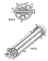
FIG. 5 shows an entrance end of the outer sleeve inFIG. 4 ; -
FIG. 6 shows three of the sleeves ofFIG. 2 as disposed inside the outer sleeve (not shown) ofFIG. 4 ; -
FIG. 7 is a block diagram of a closed system for circulating cleaning fluids through the sleeves contained in the outer sleeve ofFIG. 4 ; and -
FIG. 8 is a detail view of a fluid entrance end of the sleeve inFIG. 2 . -
FIG. 1 shows a rod-in-tube (RIT)optical fiber preform 10 that may be assembled with the aid of the present invention. Thepreform 10 includes a number of cylindrical core rods (also called "rod segments") 12 that are stacked axially end to end inside a glass overcladtube 14. Therods 12 may originate from a single long cladded core rod produced by a known modified chemical vapor deposition (MCVD) process, or by an equivalent process such as, for example, vapor axial deposition (VAD) or outside vapor deposition (OVD). Alternatively, each of therods 12 may comprise uncladded fiber core material only. Preferably, the axial end faces of therods 12 are cut flat using, e.g., a diamond saw. - The overclad
tube 14 may be obtained, for example, in the form of a commercially available silica glass cylinder. In the illustrated embodiment, the circumference of a distal orlower end 16 of thetube 14 as viewed in the drawing, is formed with a frustoconical shape and has a radially inward taper of, e.g., approximately 24 degrees. A hollowcylindrical handle 18 is formed at the top of thetube 14, and ashort glass spacer 20 is disposed at the bottom of anaxial bore 22 in thehandle 18. Thespacer 20 is constructed and arranged to block upward movement of thecore rods 12 inside thetube 14. Thespacer 20 may be inserted axially from the bottom end of the overcladtube 14 as viewed inFIG. 1 , to a position where the spacer is blocked from sliding up into the handle bore 22 by way of an annular protrusion orstep 24 on the inner circumference of thetube 14. - Further details of the
preform 10 are disclosed, for example, inUS 2004/0107735 . See also the earlier mentionedUS 2006/0216527 , which discloses a double overclad version of thepreform 10. It will be understood, however, that the inventive process as disclosed herein may be applied in general to RIT preforms of various sizes and shapes and which have one or more overclad tubes. -
FIG. 2 shows an elongatedcylindrical sleeve 40 inside which thecore rods 12 and other components are arranged to be cleaned. Thesleeve 40 facilitates the cleaning and etching of thecore rods 12, and enables the cleaned rods to be inserted directly into the overcladtube 14 inFIG. 1 together with thespacer 20 and an overcladtube plug 41 without risk of contamination. Thesleeve 40 may be formed of, e.g., polypropylene, PTFE or an equivalent material that is resistant to strong acid and base solutions. Depending on the number of thecore rods 12 to be inserted in an overclad tube, thesleeve 40 may be as long as three meters or greater. Aplastics alignment block 43 is also placed inside thesleeve 40, for aligning thesleeve 40 axially with the overcladtube 14 as explained below. - Any handles associated with the
core rods 12 are removed before the rods are inserted into thesleeve 40 for cleaning. Because the handles are typically cut off using a diamond saw, the remaining core material is subject to a risk of contamination from, inter alia, the cutting debris. Therefore, the rods must be cleaned in order to remove any contamination and/or surface water produced by prior processing or handling of the rods, and to ensure the required product quality (i.e., few breaks, high yield, and low attenuation). Thesleeve 40 is dimensioned and formed to allow one or more cleaning fluids to enter thesleeve 40 at anopen entrance end 42, and to allow the fluids to purge from anopen exit end 44 of the sleeve axially opposite theentrance end 42. The fluid flows act to clean and/or etch the exposed surfaces of thecore rods 12, as detailed below. - Fluids may be communicated to the
entrance end 42 of thesleeve 40 by way of anozzle 46 which may be part of an external washing or fluid delivery system. As shown in detail inFIG. 8 , the inside diameter of the axial passage in thesleeve 40 at theentrance end 42 is reduced, and the entrance end is formed so that thenozzle 46 can establish a fluid tight seal with the sleeve when a leading portion of thenozzle 46 is seated in theentrance end 42 to communicate fluids into the passage in the sleeve. - The
exit end 44 of thesleeve 40 is formed to allow cleaning fluids supplied at theentrance end 42 and flowing axially of the sleeve, to purge out of and away from the sleeve. Theexit end 44 is also dimensioned to allow thecore rods 12 to be inserted axially into thesleeve 40 through theexit end 44 prior to cleaning, and to be ejected out of theexit end 44 thereafter. While thecore rods 12 may be inserted by hand through the exit end for cleaning, touching of the cleaned rods before they are inserted into the overcladtube 14 must be avoided to ensure appropriate product quality for the reasons discussed above. Accordingly, as seen inFIG. 3 , aplastics push rod 60 may be inserted through theentrance end 42 of thesleeve 40, to push thecore rods 12 and certain other components inside the sleeve out of theexit end 44 and directly into the axial passage of theoverclad tube 14 inFIG. 1 . - A
push block 50 is first loaded through the exit end 44 of thesleeve 40 and, as seen inFIG. 2 , theblock 50 is disposed adjacent to theentrance end 42. SeeFIG. 8 . Theblock 50 may be formed of, e.g., polypropylene and have axial passages and/or grooves of sufficient cross section as to allow the cleaning fluids to pass from theentrance end 42, through theblock 50 and into contact with thecore rods 12 inside thesleeve 40. As seen inFIG. 8 , the reduced diameter of the sleeve passage prevents theblock 50 from moving out of theentrance end 42. - A
plastics ball 62 is next loaded through theexit end 44, followed by thetube plug 41, aplastics ball 62, a first core rod orrod segment 12, and anotherball 62. Second, third andadditional core rods 12 may then be loaded through theexit end 44, with aplastics ball 62 for separating each of therods 12. Theplastics balls 62, which are disposed between axial end faces of thecore rods 12, serve to cushion and protect the end faces from scratching while minimally contacting the end faces so that the latter are substantially exposed to the cleaning fluids inside thesleeve 40. - A removable
transverse pin 64 is inserted through the exit end 44 of thesleeve 40 to obstruct the exit end partially enough so that thepin 64, together with the reduced diameter passage at theentrance end 42 of the sleeve, will retain the parts loaded inside the sleeve and allow cleaning fluids to flow through the sleeve during a cleaning operation. If desired, markings can be scribed on the outer surface of thesleeve 40 for product identification and tracking purposes. - As seen in
FIG. 3 , after a cleaning operation and with thepin 64 withdrawn, the exit end 44 of thesleeve 40 is positioned, for example, about 5 cm away from the bottom end of theoverclad tube 14. Thepush rod 60 is inserted axially through theentrance end 42 of thesleeve 40, to displace thepush block 50 toward the left inFIG. 3 and thus urge thealignment block 43 out of the exit end 44 of the sleeve toward theoverclad tube 14. Thesleeve 40 is then positioned with respect to theoverclad tube 14 so that theblock 43 is aligned with the axial passage in the overclad tube. Thesleeve 40 and thetube 14 are then separated axially just enough to allow thealignment block 43 to fall away or otherwise be removed. - The
push rod 60 is again urged toward the left inFIG. 3 so that the cleanedspacer 20,core rods 12, and theplug 41 are displaced out of the exit end 44 of the sleeve and directly into the axial passage of thetube 14, without touching the cleaned parts manually. Theplastics balls 62 are allowed to drop away or are otherwise disposed of as thecore rods 12 are inserted into the tube passage. -
FIGS. 4 to 7 illustrate a system that allows the use of a number of thesleeves 40 simultaneously to clean core rods loaded inside the sleeves while the sleeves are contained inside a larger diameter outer tube orsleeve 70, thereby increasing productivity. The illustrated system accommodates three of thesleeves 40 each of which may be loaded with thecore rods 12 to be cleaned. The entrance ends 42 of thesleeves 40 face toward anentrance end 74 of theouter sleeve 70. The inner diameter of the axial passage in thesleeve 70 is tapered to decrease inside theentrance end 74, and theend 74 is formed to establish a fluid tight seal with afluid supply nozzle 75. It will be understood that two, three or more of thesleeves 40 may be disposed together within theouter sleeve 70 depending on, e.g., the diameters of theindividual sleeves 40 and the inside diameter of theouter sleeve 70. - A generally
cylindrical end block 72 is provided inside theentrance end 74 of theouter sleeve 70, and the reduced diameter passage obstructs theend block 72 from moving further downward. Theend block 72 has such axial passages and/or grooves as to ensure that cleaning fluids supplied to theentrance end 74 of the sleeve through thenozzle 75 will pass through theblock 72 and be distributed uniformly to the entrance ends 42 of each of thesleeves 40, and will flow in contact with the core rods inside thesleeves 40. The system ofFIGS. 4-7 may therefore omit the use of thenozzle 46 inFIGS. 2 and8 for each of thesleeves 40. - The
exit end 76 of theouter sleeve 70 preferably contains an annularanti-float ring 78 dimensioned and arranged to rest atop each of thesleeves 40, and a removabletransverse pin 79 inserted through the exit end 76 of thesleeve 70 just above thering 78. Thering 78 and thepin 79 together act to restrain the individual loadedsleeves 40 from moving or floating upward during a cleaning operation as explained below. - Although not required in order to practice the inventive process, the exit end 76 of the
outer sleeve 70 may be enclosed or capped as shown inFIG. 7 to form a closed fluid delivery system and provide for increased safety and efficiency. InFIG. 7 , one end of aconduit 80 communicates with the exit end 76 of thesleeve 70, and is arranged to return cleaning fluids purging from theexit end 76 to a fluid circulation system 82 at the opposite end of theconduit 80. TheFIG. 7 arrangement prevents acids and other potentially harmful liquids from escaping when the liquids are flowing inside thesleeves sleeve 70 for collection in an outside return basin. - The core rods 12 (or other glass preform parts) contained in the
sleeves 40 may be washed and cleaned by allowing various fluids supplied to theentrance end 74 of theouter sleeve 70, to enter the entrance ends 42 of thesleeves 40 and flow over exposed surfaces of the contained rods. A washing and cleaning operation may proceed, for example, as follows: - 1. Rinsing the
rods 12 by flowing high purity deionized water for several minutes. - 2. Dissolving surface dirt and grease on the rods by flowing a liquid surfactant or cleaning detergent.
- 3. Rinsing the rods again with a flow of deionized water.
- 4. Etching the rods by flowing a 25 to 49% HF acid solution for a few minutes to a few hours, depending on the condition (e.g., OH content) of the rod surfaces.
- 5. Rinsing the rods a third time with a flow of deionized water.
- 6. Flowing an inert drying gas such as N2 or clean air to dry the rods.
- The circulation system 82 should be capable of maintaining a supply pressure sufficient to overcome the heights of the
sleeves FIG. 7 . That is, the supply pressure should exceed the hydrostatic pressure developed at the entrance ends of the sleeves when the sleeves are supported vertically and are liquid filled, so that liquid circulation can be maintained by the system 82 over an entire cleaning operation. - As noted, the
sleeves glass rods 12. Once cleaned, the components may be urged (e.g., by a long clean rod) out of thesleeves - As disclosed herein, the inventive method enables core rods or other components associated with optical fiber preforms to be safely transported, identified, cleaned, etched, stored, and then assembled to produce an optical fiber preform. Any risk of contamination from prior handling is substantially reduced or eliminated. The method is compatible with most if not all current RIT preform manufacturing processes, and is suited for core rods produced by known MCVD, VAD, JVD or OVD techniques.
Claims (10)
- A method of cleaning glass components (12, 20, 41) associated with optical fiber preforms (10), characterized by:providing a number of first sleeves (40) each having an axis, an entrance end (42), and an exit end (44) axially opposite to the entrance end (42);loading one or more glass preform components (12, 20, 41) into each of the first sleeves (40);partially obstructing the entrance (42) and the exit ends (44) of each of the first sleeves (40) for retaining the loaded components (12, 20, 41) inside the first sleeves (40);providing a second sleeve (70) having an axis, an entrance end (74), and an exit end (76) axially opposite to the entrance end (74) of the second sleeve (70);placing the loaded first sleeves (40) together inside the second sleeve (70) so that the entrance ends (42) of the first sleeves (40) face toward the entrance end (74) of the second sleeve (70);coupling the entrance end (74) of the second sleeve (70) with a fluid delivery system (82);supplying one or more fluids from the delivery system (82) to the entrance end (74) of the second sleeve (70) so that the fluids flow into the entrance ends (42) of the first sleeves (40) and make contact with exposed surfaces of the components inside the first sleeves (40) to clean or to etch the components; andpurging the fluids from the exit ends (44) of the first sleeves (40), and directing the purged fluids out of the exit end (76) of the second sleeve (70).
- The method of claim 1, characterized in that the fluid supplying step includes flowing a liquid surfactant or detergent for cleaning the components (12, 20, 41).
- The method of claim 1, characterized in that the fluid supplying step includes flowing a HF acid solution for etching the components (12, 20, 41).
- The method of claim 1, characterized in that the fluid supplying step includes flowing water for rinsing the components (12, 20, 41).
- The method of claim 1, characterized in that the fluid supplying step includes flowing a drying gas for drying the components (12, 20, 41).
- The method of claim 1, characterized by capping the exit end (76) of the second sleeve (70) and communicating fluids purged from the exit end (76) of the second sleeve (70) to a fluid circulation system (82).
- The method of claim 1, characterized by supporting the first and the second sleeves (40, 70) vertically during the fluid supplying step.
- The method of any one of claims 1 to 7, characterized in that the glass components to be cleaned comprise core rods (12) for optical fiber preforms (10), and by loading the core rods (12) into each of the first sleeves (40).
- The method of claim 8, characterized by placing separating members (62) between axial end faces of core rods (12) loaded successively in each of the first sleeves (40).
- A method of assembling core rods (12) in an optical fiber preform (10), characterized by:cleaning the core rods (12) according to the method of claim 8 or claim 9; andinserting the cleaned core rods (12) into an overclad tube (14) of an optical fiber preform (10), by;axially aligning a first end (44) of a given one of the loaded first sleeves (40) with a passage in the overclad tube (14) after the cleaning step; andinserting a push rod (60) through a second end (42) of the first sleeve (40) axially opposite the first end (44), for urging the cleaned core rods (12) out of the first end (44) of the first sleeve (40) and into the passage of the overclad tube (14).
Applications Claiming Priority (1)
| Application Number | Priority Date | Filing Date | Title |
|---|---|---|---|
| US11/582,168 US7722777B2 (en) | 2006-10-17 | 2006-10-17 | Method of preparing core rods for optical fiber preforms |
Publications (2)
| Publication Number | Publication Date |
|---|---|
| EP1925599A1 EP1925599A1 (en) | 2008-05-28 |
| EP1925599B1 true EP1925599B1 (en) | 2009-01-14 |
Family
ID=37740426
Family Applications (1)
| Application Number | Title | Priority Date | Filing Date |
|---|---|---|---|
| EP06024170A Ceased EP1925599B1 (en) | 2006-10-17 | 2006-11-21 | Method of preparing core rods for optical fiber preforms |
Country Status (5)
| Country | Link |
|---|---|
| US (1) | US7722777B2 (en) |
| EP (1) | EP1925599B1 (en) |
| JP (1) | JP4989358B2 (en) |
| CN (1) | CN101164937B (en) |
| DE (1) | DE602006004892D1 (en) |
Cited By (1)
| Publication number | Priority date | Publication date | Assignee | Title |
|---|---|---|---|---|
| US10308541B2 (en) | 2014-11-13 | 2019-06-04 | Gerresheimer Glas Gmbh | Glass forming machine particle filter, a plunger unit, a blow head, a blow head support and a glass forming machine adapted to or comprising said filter |
Families Citing this family (13)
| Publication number | Priority date | Publication date | Assignee | Title |
|---|---|---|---|---|
| US8468852B2 (en) * | 2009-12-03 | 2013-06-25 | Corning Incorporated | Soot pressing for optical fiber overcladding |
| RU2437129C1 (en) * | 2010-03-24 | 2011-12-20 | Закрытое акционерное общество "Профотек" | Method of making birefringent microstructured optical fibre |
| NL1041529B1 (en) | 2015-10-16 | 2017-05-02 | Draka Comteq Bv | A method for etching a primary preform and the etched primary preform thus obtained. |
| CA3070060A1 (en) * | 2017-01-27 | 2018-08-02 | Sterlite Technologies Limited | Optical fiber draw assembly and fabricated optical fiber thereof |
| CN108144907B (en) * | 2017-12-29 | 2023-11-03 | 通鼎互联信息股份有限公司 | OVD plug cleaning equipment |
| CN108675626A (en) * | 2018-04-10 | 2018-10-19 | 中国科学院西安光学精密机械研究所 | A method for reducing the impurity and hydroxyl content at the interface of the rod tube and the sleeve of the optical fiber preform rod |
| US11787727B2 (en) * | 2018-04-18 | 2023-10-17 | Lawrence Livermore National Security, Llc | Method for fabrication of sleeveless photonic crystal canes with an arbitrary shape |
| CN112239323B (en) * | 2020-10-23 | 2022-11-04 | 杭州富通通信技术股份有限公司 | Processing technology of prefabricated rod |
| CN117396447B (en) * | 2021-05-21 | 2026-05-05 | 康宁股份有限公司 | Multi-core optical fibers based on preforms and their formation methods |
| CN114409242B (en) * | 2021-12-01 | 2023-08-18 | 浙江富通光纤技术有限公司 | Process for manufacturing optical fiber preform and optical fiber |
| CN116606066A (en) * | 2023-06-13 | 2023-08-18 | 华南师大(清远)科技创新研究院有限公司 | Optical fiber preform and preparation method thereof |
| US20250002391A1 (en) * | 2023-06-30 | 2025-01-02 | Sterlite Technologies Limited | Optical Fiber Drawing Apparatus and Method Thereof |
| CN117732789A (en) * | 2023-12-29 | 2024-03-22 | 远东通讯有限公司 | Preform rod vertical pickling equipment and pickling method thereof |
Family Cites Families (17)
| Publication number | Priority date | Publication date | Assignee | Title |
|---|---|---|---|---|
| JP2525351B2 (en) * | 1985-08-08 | 1996-08-21 | キヤノン株式会社 | camera |
| US5618326A (en) * | 1991-09-30 | 1997-04-08 | British Telecommunications Public Limited Company | Surface treatment of halide glass articles |
| JP3343379B2 (en) * | 1992-12-14 | 2002-11-11 | 昭和電線電纜株式会社 | Preform rod etching equipment |
| US5917109A (en) * | 1994-12-20 | 1999-06-29 | Corning Incorporated | Method of making optical fiber having depressed index core region |
| US5894537A (en) * | 1996-01-11 | 1999-04-13 | Corning Incorporated | Dispersion managed optical waveguide |
| US5834786A (en) * | 1996-07-15 | 1998-11-10 | Diamond Semiconductor Group, Inc. | High current ribbon beam ion implanter |
| US5897679A (en) * | 1997-08-27 | 1999-04-27 | Lucent Technologies Inc. | Dimensional control in the manufacture of optical fiber ferrule connectors by etching |
| US6243522B1 (en) * | 1998-12-21 | 2001-06-05 | Corning Incorporated | Photonic crystal fiber |
| US6446468B1 (en) * | 2000-08-01 | 2002-09-10 | Fitel Usa Corp. | Process for fabricating optical fiber involving overcladding during sintering |
| WO2002024590A1 (en) * | 2000-09-21 | 2002-03-28 | Mitsubishi Cable Industries,Ltd. | Method of manufacturing photonic crystal fiber |
| DE10245987B3 (en) * | 2002-10-02 | 2004-05-06 | Schott Glas | Optical step fibers from multi-component glasses |
| US20040107735A1 (en) | 2002-12-04 | 2004-06-10 | Fitel Usa Corp. | Rod-in-tube optical fiber preform and method |
| CA2454896A1 (en) * | 2003-01-16 | 2004-07-16 | Sumitomo Electric Industries, Ltd. | Method of producing optical fiber preform, and optical fiber preform and optical fiber produced with the method |
| WO2004101456A1 (en) * | 2003-05-19 | 2004-11-25 | Sumitomo Electric Industries, Ltd | Optical fiber and method of producing the same |
| CN1317212C (en) * | 2004-04-29 | 2007-05-23 | 斯德莱特光学技术有限公司 | A low-attenuation optical fiber in the 1380nm wavelength region and its preparation method |
| US7641969B2 (en) * | 2005-03-23 | 2010-01-05 | Fletcher Iii Joseph P | Optical fiber preform with overclad tubes |
| CA2648674A1 (en) * | 2008-01-08 | 2009-07-08 | Institut National D'optique | Polarization-maintaining optical fiber and method for manufacturing the same |
-
2006
- 2006-10-17 US US11/582,168 patent/US7722777B2/en active Active
- 2006-11-21 DE DE602006004892T patent/DE602006004892D1/en active Active
- 2006-11-21 EP EP06024170A patent/EP1925599B1/en not_active Ceased
- 2006-12-21 CN CN2006101685849A patent/CN101164937B/en not_active Expired - Fee Related
-
2007
- 2007-08-13 JP JP2007210591A patent/JP4989358B2/en active Active
Cited By (1)
| Publication number | Priority date | Publication date | Assignee | Title |
|---|---|---|---|---|
| US10308541B2 (en) | 2014-11-13 | 2019-06-04 | Gerresheimer Glas Gmbh | Glass forming machine particle filter, a plunger unit, a blow head, a blow head support and a glass forming machine adapted to or comprising said filter |
Also Published As
| Publication number | Publication date |
|---|---|
| CN101164937B (en) | 2011-09-21 |
| DE602006004892D1 (en) | 2009-03-05 |
| US20080087303A1 (en) | 2008-04-17 |
| EP1925599A1 (en) | 2008-05-28 |
| JP4989358B2 (en) | 2012-08-01 |
| JP2008100899A (en) | 2008-05-01 |
| US7722777B2 (en) | 2010-05-25 |
| CN101164937A (en) | 2008-04-23 |
Similar Documents
| Publication | Publication Date | Title |
|---|---|---|
| JP4989358B2 (en) | Method for making core rod for optical fiber preform | |
| JP5111771B2 (en) | Optical fiber preform with overclad tube | |
| US11834365B2 (en) | Optical fiber preform production method, optical fiber preform, and optical fiber production method | |
| FI77217C (en) | Process for producing a polarization preserving optical fiber | |
| KR20060007434A (en) | Optical fiber and its manufacturing method | |
| CN103951181B (en) | A kind of sleeve pipe prefabricated rods of structure-improved and manufacture method thereof | |
| US7854146B2 (en) | Method for production of an optical component from quartz glass | |
| KR20010014487A (en) | Method and apparatus for washing or hydration of ophthalmic devices | |
| US20240051865A1 (en) | Optical fiber preform production method, optical fiber preform, and optical fiber production method | |
| CN105073662B (en) | Method for manufacturing optical fiber preform and optical fiber | |
| CN112239323B (en) | Processing technology of prefabricated rod | |
| KR20040024598A (en) | The Method for fabricating a low polarization mode dispersion optical fiber | |
| WO2014107189A1 (en) | Manufacture of bend insensitive multimode optical fiber | |
| CN101014545B (en) | Elongation method for prpoducing an optical component of quartz glass and preliminary product suited for performing the method | |
| EP1182173A1 (en) | Preform for optical fibres and methods for making the preform and optical fibres | |
| EP0630864A2 (en) | Fabrication process of polarization-maintaining optical fiber | |
| JP5995646B2 (en) | Manufacturing method of optical fiber preform and manufacturing method of hole structure optical fiber | |
| JP5644693B2 (en) | Optical fiber manufacturing method | |
| CN115784599B (en) | A low crosstalk image transmission optical fiber and preparation method thereof | |
| CN110304823A (en) | Manufacturing method of multi-core optical fiber | |
| WO2002098808A1 (en) | Method of low pmd optical fiber manufacture | |
| JP5644694B2 (en) | Optical fiber manufacturing method | |
| JP2001247324A (en) | Manufacturing method of preform for optical fiber and preform | |
| KR100777498B1 (en) | Method for improving joint interface in overcladding process and apparatus for same | |
| JP2004035369A (en) | Method of manufacturing optical fiber preform |
Legal Events
| Date | Code | Title | Description |
|---|---|---|---|
| PUAI | Public reference made under article 153(3) epc to a published international application that has entered the european phase |
Free format text: ORIGINAL CODE: 0009012 |
|
| 17P | Request for examination filed |
Effective date: 20061121 |
|
| AK | Designated contracting states |
Kind code of ref document: A1 Designated state(s): AT BE BG CH CY CZ DE DK EE ES FI FR GB GR HU IE IS IT LI LT LU LV MC NL PL PT RO SE SI SK TR |
|
| AX | Request for extension of the european patent |
Extension state: AL BA HR MK RS |
|
| GRAP | Despatch of communication of intention to grant a patent |
Free format text: ORIGINAL CODE: EPIDOSNIGR1 |
|
| GRAS | Grant fee paid |
Free format text: ORIGINAL CODE: EPIDOSNIGR3 |
|
| GRAA | (expected) grant |
Free format text: ORIGINAL CODE: 0009210 |
|
| AK | Designated contracting states |
Kind code of ref document: B1 Designated state(s): DE FR GB |
|
| REG | Reference to a national code |
Ref country code: GB Ref legal event code: FG4D |
|
| AKX | Designation fees paid |
Designated state(s): DE FR GB |
|
| REF | Corresponds to: |
Ref document number: 602006004892 Country of ref document: DE Date of ref document: 20090305 Kind code of ref document: P |
|
| PLBE | No opposition filed within time limit |
Free format text: ORIGINAL CODE: 0009261 |
|
| STAA | Information on the status of an ep patent application or granted ep patent |
Free format text: STATUS: NO OPPOSITION FILED WITHIN TIME LIMIT |
|
| 26N | No opposition filed |
Effective date: 20091015 |
|
| REG | Reference to a national code |
Ref country code: FR Ref legal event code: PLFP Year of fee payment: 10 |
|
| REG | Reference to a national code |
Ref country code: FR Ref legal event code: PLFP Year of fee payment: 11 |
|
| REG | Reference to a national code |
Ref country code: FR Ref legal event code: PLFP Year of fee payment: 12 |
|
| PGFP | Annual fee paid to national office [announced via postgrant information from national office to epo] |
Ref country code: GB Payment date: 20201127 Year of fee payment: 15 Ref country code: FR Payment date: 20201125 Year of fee payment: 15 |
|
| PGFP | Annual fee paid to national office [announced via postgrant information from national office to epo] |
Ref country code: DE Payment date: 20211126 Year of fee payment: 16 |
|
| GBPC | Gb: european patent ceased through non-payment of renewal fee |
Effective date: 20211121 |
|
| PG25 | Lapsed in a contracting state [announced via postgrant information from national office to epo] |
Ref country code: GB Free format text: LAPSE BECAUSE OF NON-PAYMENT OF DUE FEES Effective date: 20211121 |
|
| PG25 | Lapsed in a contracting state [announced via postgrant information from national office to epo] |
Ref country code: FR Free format text: LAPSE BECAUSE OF NON-PAYMENT OF DUE FEES Effective date: 20211130 |
|
| REG | Reference to a national code |
Ref country code: DE Ref legal event code: R119 Ref document number: 602006004892 Country of ref document: DE |
|
| P01 | Opt-out of the competence of the unified patent court (upc) registered |
Effective date: 20230411 |
|
| PG25 | Lapsed in a contracting state [announced via postgrant information from national office to epo] |
Ref country code: DE Free format text: LAPSE BECAUSE OF NON-PAYMENT OF DUE FEES Effective date: 20230601 |