EP1925581A1 - Car upper side handrail device of elevator - Google Patents
Car upper side handrail device of elevator Download PDFInfo
- Publication number
- EP1925581A1 EP1925581A1 EP05783678A EP05783678A EP1925581A1 EP 1925581 A1 EP1925581 A1 EP 1925581A1 EP 05783678 A EP05783678 A EP 05783678A EP 05783678 A EP05783678 A EP 05783678A EP 1925581 A1 EP1925581 A1 EP 1925581A1
- Authority
- EP
- European Patent Office
- Prior art keywords
- handrail
- car
- handrail device
- vertical pillar
- pin
- Prior art date
- Legal status (The legal status is an assumption and is not a legal conclusion. Google has not performed a legal analysis and makes no representation as to the accuracy of the status listed.)
- Withdrawn
Links
Images







Classifications
-
- B—PERFORMING OPERATIONS; TRANSPORTING
- B66—HOISTING; LIFTING; HAULING
- B66B—ELEVATORS; ESCALATORS OR MOVING WALKWAYS
- B66B5/00—Applications of checking, fault-correcting, or safety devices in elevators
- B66B5/0043—Devices enhancing safety during maintenance
- B66B5/005—Safety of maintenance personnel
- B66B5/0081—Safety of maintenance personnel by preventing falling by means of safety fences or handrails, being operable or not, mounted on top of the elevator car
Definitions
- the present invention relates to a handrail device for an elevator car, which is erected in a top portion of the car when elevator maintenance work is performed, and is folded and stored in the top portion of the car when the handrail device is not needed.
- Patent Document 1 Japanese Patent Laid-Open No. 2000-143125 ( Figure 3 )
- the present invention has been made to solve the above problems, and accordingly an object thereof is to provide a handrail device of an elevator car, the assembling work and storing work of which are easy, and which can be configured at a low cost.
- the present invention provides a handrail device of an elevator car, which is erected in a top portion of the car when elevator maintenance work is performed, and is folded and stored in the top portion of the car when the handrail device is not needed comprises a handrail device having handrails and vertical pillars for supporting the handrails, an upper pin and a lower pin which are provided in a lower end portion of the vertical pillar and are arranged above and below in an assembled state of the handrail device, and a connecting portion which is provided in the top portion of the car and to which the lower end portion of the vertical pillar is turnably connected, the connecting portion comprising a guide portion which engages with one of the upper pin and the lower pin to guide the vertical pillar vertically through a predetermined direction, and a regulating portion with which the other of the upper pin and the lower pin engages from the upside to regulate the turning of the vertical pillar in the assembled state of the handrail device. Therefore, the assembling work and storing work are easy, and the handrail device can be configured at a low cost.
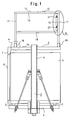
- Figure 1 is a side view showing a construction of a handrail device of an elevator car in Embodiment 1 of the present invention
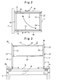
- Figure 2 is a plan view of the handrail device of an elevator car shown in Figure 1
- Figure 3 is a front view of the handrail device of an elevator car shown in Figure 1
- Figure 4 is a detailed view of portion A of the handrail device of an elevator car shown in Figure 1
- Figure 5 is a front view of the handrail device of an elevator car shown in Figure 4
- Figure 6 is a detailed view of portion B of the handrail device of an elevator car shown in Figure 1
- Figure 7 is a sectional view taken along the line X-X of the handrail device of an elevator car shown in Figure 6 .
- reference numeral 1 denotes a cab into which the elevator users get in and out.
- This cab 1 is supported by a car frame 3 via a plurality of cushioning materials 2.
- the car frame 3 is formed by a car lower frame 4 which is arranged under the cab 1 to support the cab 1, car frame stiles 5 each having a substantially U-shaped transverse cross section, which are arranged on both sides of the cab 1 and the lower end portions of which are provided on the car lower frame 4, and a car upper frame 6 arranged above the top surface of the cab 1 to connect the upper end portions of the car frame stiles 5 to each other in the width direction of the car.
- reference numeral 7 denotes a car door driving device which is provided on the car entrance side of the car upper frame 6 to drive a car door 8 for opening and closing the car entrance.
- the car upper frame 6 is formed by side beams 9a and 9b consisting of right and left beams which are arranged in the car depth direction and the intermediate portions of which are fixed to the upper end portions of the car frame stiles 5, a front beam 10 which is provided between the front end portions of the side beams 9a and 9b to connect the front end portions of the side beams 9a and 9b to each other in the car width direction, and a rear beam 11 which is provided between the rear end portions of the side beams 9a and 9b to connect the rear end portions of the side beams 9a and 9b to each other in the car width direction.
- the car upper frame 6 has a substantially quadrangular ring shape as a whole.
- the side beams 9a and 9b, the front beam 10 and the rear beam 11 each are formed by a square pipe, and both end portions of the front beam 10 and the rear beam 11 are joined to the side beams 9a and 9b by welding.
- FIGS 1 to 7 show a state in which the handrail device 12 has been assembled and erected in the top portion of the car when elevator maintenance is performed (hereinafter referred to as an "assembled state").
- the handrail device 12 is formed by a right handrail 13 and a left handrail 14 arranged on the right side and the left side of the top portion of the car, respectively, when being viewed from the elevator hall side, and a rear handrail 15 arranged on the rear side of the top portion of the car.
- Reference numeral 16 denotes connecting portions which are provided in both end portions of the front beam 10 and both end portions of the rear beam 11 of the car upper frame 6 to connect the lower end portions of the right handrail 13 and the left handrail 14 so as to be turnable within a predetermined angle.
- the right handrail 13 and a left handrail 14 each include two vertical pillars 17 arranged on the front side and the rear side of the car, an upper handrail 18 joined to the upper end portions of both the vertical pillars 17 by welding to connect the upper end portions of the vertical pillars 17 to each other in the car depth direction, and a lower handrail 19 arranged in the car depth direction so as to be substantially parallel with the upper handrail 18 by being joined by welding to intermediate portions of both the vertical pillars 17.
- the upper handrail 18, the lower handrail 19, and the vertical pillars 17 for supporting the upper handrail 18 and the lower handrail 19 each are formed by a square pipe.
- each of the vertical pillars 17 there are provided a lower pin 20 and an upper pin 21 which are arranged above and below in the assembled state of the handrail device 12.
- the lower pin 20 and the upper pin 21 are arranged in the car depth direction so as to be parallel with each other, and are provided so that both end portions thereof protrude through a predetermined distance from the front side surface and the rear side surface of the vertical pillar 17.
- the connecting portion 16 for turnably connecting the lower end portion of the vertical pillar 17 to the front beam 10 and the rear beam 11 is provided with a guide portion, which engages with one of the lower pin 20 and the upper pin 21 to guide the vertical pillar 17 to the above through a predetermined distance, and a regulating portion, with which the other of the lower pin 20 and the upper pin 21 is engaged from the above to regulate the turning of the vertical pillar 17 in the assembled state of the handrail device 12.
- the connecting portions 16 in Embodiment 1 consist of mounting fixtures 22 which each have a substantially U-shaped transverse cross section, and is erected on the upper surfaces of the end portions of the front beam 10 and the rear beam 11 so that the open end of the U-shaped portion faces to the car center portion in the plan view.
- a guide hole 22a guide portion
- a stopper groove 22b regulating portion
- the lower end portion of the vertical pillar 17 is arranged in the U-shaped portion of the mounting fixture 22 in other words, between the parallel plates.
- the lower pin 20 is arranged penetratingly with a play, and in the stopper grooves 22b, the upper pin 21 is arranged.
- the vertical pillars 17 are directly mounted on the front beam 10 so that vertical loads acting on the handrail device 12 and the weight of the handrail device 12 are supported by the front beam 10 and the rear beam 11.
- a small gap is formed between the lower pin 20 and the lower edge of the guide hole 22a and between the upper pin 21 and the lower edge of the stopper groove 22b, so that the above-mentioned vertical loads do not act on the lower pin 20 and the upper pin 21.
- the rear handrail 15 is formed by joining four square pipes to each other by welding into a quadrangular ring shape, and includes vertical pillars 23 on both sides, an upper handrail 24 that connects the upper end portions of both the vertical pillars 23, and a lower handrail 25 that connects the lower end portions of both the vertical pillars 23.
- the rear handrail 15 is connected so that the vertical pillar 23 on the left side is freely turned with respect to the vertical pillar 17 on the rear side of the left handrail 14 by turning devices 26 (not shown in Figures 1 to 7 ), and the vertical pillar 23 on the right side is locked to the vertical pillar 17 on the rear side of the right handrail 13 by locking devices 27.
- the distance between the upper handrail 24 and the lower handrail 25 of the rear handrail 15 is shorter than the distance between the upper handrail 18 and the lower handrail 19 of the left handrail 14 supported by the turning devices 26, and the rear handrail 15 is arranged within the height between the upper handrail 18 and the lower handrail 19 of the left handrail 14.
- the locking device 27 is made up of a substantially L-shaped mounting plate 27a provided on the vertical pillar 17 on the rear side of the right handrail 13 and a wing bolt 27b screwed in the vertical pillar 23 on the right side of the rear handrail 15.
- the wing bolt 27b is tightened to hold the mounting plate 27a by using the side surface of the vertical pillar 23 of the rear handrail 15 and the wing bolt 27b, by which the vertical frame 23 on the right side of the rear handrail 15 is fixed to the vertical pillar 17 on the rear side of the right handrail 13.
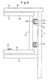
- FIG 8 is a detailed view of an essential portion for illustrating a folding operation of the handrail device of an elevator car in Embodiment 1 of the present invention
- Figure 9 is a side view for illustrating a folding operation of the handrail device of an elevator car in Embodiment 1 of the present invention
- Figures 10 and 12 are front views for illustrating a folding operation of the handrail device of an elevator car in Embodiment 1 of the present invention
- Figure 11 is a detailed view of portion C of the handrail device of an elevator car shown in Figure 10 .
- the elevator maintenance worker first loosens the wing bolts 27b of the locking devices 27, thereby removing the vertical pillar 23 on the right side of the rear handrail 15 from the vertical pillar 17 on the rear side of the right handrail 13, and turns the rear handrail 15 around the turning devices 26 to move the rear handrail 15 to the left handrail 14 side.
- the rear handrail 15 can be arranged within a space formed by the vertical pillars 17 on both sides of the left handrail 14, the upper handrail 18, and the lower handrail 19. That is to say, the rear handrail 15 is configured so as to be stored within the thickness of the left handrail 14.
- Figure 8 shows an essential portion in the state in which the rear handrail 15 is arranged within the thickness of the left handrail 14.
- a substantially U-shaped supporting member 26a provided on the vertical pillar 17 on the rear side of the left handrail 14 and a substantially U-shaped supporting member 26b provided on the vertical pillar 23 on the left side of the rear handrail 15 are pivotally provided by a pin 26c having an axis in the vertical direction.
- the configuration is made such that when the rear handrail 15 is arranged within the thickness of the left handrail 14, the supporting members 26a and 26b and pins 26c are also arranged within the thickness of the left handrail 14 like the rear handrail 15.
- a locking device denoted by the reference numeral of 28 is used for fixing the rear handrail 15 to the left handrail 14 to prevent the rear handrail 15 from moving when the rear handrail 15 is arranged within the thickness of the left handrail 14.
- FIG. 11 shows a configuration of the lower part of the vertical pillar 17 and the connecting portion 16 at the time when the right handrail 13 and the left handrail 14 are stored in the top portion of the car.
- the maintenance worker first raises the right handrail 13 upward, and thereby moves the vertical pillars 17 on the front side and the rear side upward.
- the lower pin 20 is guided by the guide hole 22a formed in the mounting fixture 22, by which the lower end portion of the vertical pillar 17 is moved upward along the lengthwise direction of the guide hole 22a. Both end portions of the lower pin 20 project to the outside of the mounting fixture 22 via the guide hole 22a. Therefore, in the state in which the lower pin 20 is installed, the vertical pillar 17 cannot be removed completely from the connecting portion 16.
- the upper pin 21 provided above the lower pin 20 is also moved together with the lower pin 20.
- the upper pin 21 moves from the opening end of the stopper groove 22b to a position above the mounting fixture 22, by which the upper pin 21 is disengaged from the stopper groove 22b.
- the vertical frame 17 can be turned around the lower pin 20. Therefore, the maintenance worker raises the right handrail 13 to a height at which the upper pin 21 does not interfere with the mounting fixture 22 when the vertical frame 17 is turned, and thereafter brings down the right handrail 13 to the central side of the car to place it on the car upper frame 6.
- the maintenance worker brings down the left handrail 14 to the central side of the car by the same procedure as described above, and places the left handrail 14 on the right handrail 13 having been folded on the car upper frame 6.
- the left handrail 14 is arranged horizontally on the right handrail 13. That is to say, the vertical length of the guide hole 22a formed in the mounting fixture 22 is set so as to match the position of the lower pin 20 moving upward by the thickness of the right handrail 13 when the left handrail 14 is placed horizontally on the right handrail 13.
- Figure 12 shows a state in which the right handrail 13 and the left handrail 14 are placed on the car upper frame 6 and the handrail device 12 is folded completely (hereinafter, referred to as a "stored state").
- the maintenance worker assembles the handrail device 12 in the top portion of the car by reversing the procedure for the storage. Specifically, the maintenance worker first raises the left handrail 14 placed in the top portion of the car so as to turn it around the lower pin 20. Then, after making the left handrail 14 in an upright state, the maintenance worker lowers the left handrail 14 slowly and erects it on the car upper frame 6 so that the upper pin 21 provided in the lower end portion of the vertical pillar 17 is arranged in the stopper groove 22b of the connecting portion 16. Also, the maintenance worker erects the right handrail 13 on the car upper frame 6 by the same procedure as described above.
- the maintenance worker loosens the wing bolt of the locking device 28, thereby making the rear handrail 15 in a turnable state, and turns the rear handrail 15 around the turning devices 26 and moves it to the right handrail 13 side.
- the vertical pillar 23 on the right side of the rear handrail 15 is fixed to the vertical pillar 17 on the rear side of the right handrail 13.
- Embodiment 1 of the present invention when the right handrail 13 or the left handrail 14 is assembled, merely by engaging the upper pin 21 provided in the lower end portion of the vertical pillar 17 with the stopper groove 22b of the mounting fixture 22, an effect of preventing the handrail device 12 from overturning can be achieved, so that the conventional stoppers, latch mechanisms, and the like which are provided only for preventing the overturn of the assembled handrail device 12, are unnecessary. Therefore, work that is performed by the maintenance worker in a stooping posture to prevent the overturn of the handrail device 12 is not needed, which improves the work efficiency, and thereby the assembling time and storing time can be shortened. Also, since the conventional stoppers, latch mechanisms, and the like need not be provided, the construction can be simplified, and hence the handrail device 12 can be provided at a low cost.
- the handrail device 12 is stored by being placed on the car upper frame 6 provided at a position separating upward a predetermined distance from the top surface of the cab 1, there is no fear that elevator equipment installed on the top surface of the cab 1 is damaged, and also a phenomenon that the vibrations of a fan etc. installed on the top surface of the cab 1 transmit to the handrail device 12 to generate noise can be prevented.
- the rear handrail 15 of the stored handrail device 12 is arranged within the thickness of the left handrail 14, the total thickness of the handrail device 12 placed on the car upper frame 6 can be kept to only the sum of the thickness of the right handrail 13 and the thickness of the left handrail 14. It is a matter of course that even if the rear handrail 15 cannot be arranged within the thickness of the left handrail 14, the same effect as described above can be achieved if the rear handrail 15 can be arranged within the thicknesses of the right handrail 13 and the left handrail 14 in the stored state of the handrail device 12.
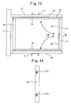
- Figure 13 is a plan view showing a construction of a handrail device of an elevator car in Embodiment 2 of the present invention
- Figure 14 is a sectional view taken along the line Y-Y of the handrail device of an elevator car shown in Figure 13 .
- the rear handrail 15 of the handrail device 12 is made up of a right rear handrail 29 provided on the vertical pillar 17 on the rear side of the right handrail 13 so as to be turnable via turning devices (not shown) and a left rear handrail 30 provided on the vertical pillar 17 on the rear side of the left handrail 14 so as to be turnable via the turning devices 26.
- Both of the right rear handrail 29 and the left rear handrail 30 each are formed by joining square pipes to each other into a quadrangular ring shape by welding, and in the assembled state of the handrail device 12, the adjacent vertical pillars are connected to each other by locking devices 27c.
- the handrail device 12 is stored, the right rear handrail 29 and the left rear handrail 30 each are turned around the turning devices 26 etc., and are stored within the thickness of the right handrail 13 and the thickness of the left handrail 14, respectively.
- the turning ranges of the right rear handrail 29 and the left rear handrail 30 can be kept narrow, so that the work efficiency at the time of assembling and at the time of storing can be improved. Also, even in the case where the width of the rear handrail 15 is wider than the width of the right handrail 13 or the left handrail 14, namely, the width of the car is wide, the same effect as described above can be achieved.
- Figure 15 is a front view showing a construction of a handrail device of an elevator car in Embodiment 2 of the present invention
- Figure 16 is a view for illustrating a construction of a handrail device of an elevator car in Embodiment 2 of the present invention, showing the construction of the handrail device 12 in the case where the width of the car is wide.
- a substantially Z-shaped raising member 31 is provided on the upper surface in the left end portion of the car upper frame 6.
- the vertical pillar 17 of the left handrail 14 is placed horizontally on the raising member 31 and the right handrail 13. That is to say, the raising member 31 has a height same as the thickness of the right handrail 13, and is arranged at a position under the vertical pillar 17 of the left handrail 14 in the stored state.
- the left handrail 14 is inclined undesirably in the stored state of the handrail device 12. Therefore, by providing the above-described construction, the handrail device 12 in the stored state is arranged horizontally on the car upper frame 6, and thus the thickness thereof can be kept to only the sum of the thickness of the right handrail 13 and the thickness of the left handrail 14, so that interference with equipment on the top surface of the cab 1 can be prevented. Also, since the left handrail 14 can be kept horizontal, the car is stable even when moving up and down, and also there is no fear that vibrations and noise such as chattering noise are generated. As for the others, the same configuration and effect as those of Embodiment 1 are achieved.
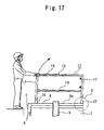
- Figure 17 is a side view for illustrating a folding operation of a handrail device of an elevator car in Embodiment 3 of the present invention
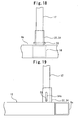
- Figure 18 is a detailed view of portion D of the handrail device of an elevator car shown in Figure 17
- Figure 19 is a front view of the handrail device of an elevator car shown in Figure 18 .
- the front sides of the right handrail 13 and the left handrail 14, namely, the elevator boarding side has the same construction as that of Embodiment 1 and Embodiment 2.
- the mounting fixtures 22 provided on the car upper frame 6 and the lower pins 20 and the upper pins 21 provided in the lower end portions of the vertical pillars 17 are provided.
- connecting portions 32 erected in the end portions of the rear beam 11 of the car upper frame 6 and lower pins 33 provided in the lower end portions of the vertical pillars 17 are provided.
- the connecting portions 32 consist of mounting fixtures 34 which each have a substantially U-shaped transverse cross section, and is arranged so that the open end of the U-shaped portion faces to the car center portion in the plan view.
- a guide hole 34a consisting of an elongated hole having a lengthwise direction in the vertical direction is formed.
- the lower pin 33 has the same construction as that of the lower pin 20 in Embodiment 1 and Embodiment 2. Specifically, the lower pin 33 is provided so that the lengthwise direction thereof is arranged in the depth direction of car, and both end portions project through a predetermined distance from the front side surface and the rear side surface of the vertical frame 17. That is to say, on the side opposite to the elevator boarding side, an element corresponding to the upper pin 21 and the stopper groove 22b in Embodiment 1 and Embodiment 2 is not provided.
- the assembling work and storing work for the handrail device 12 performed by the elevator maintenance worker can be lightened.
- the maintenance worker when raising the right handrail 13 and the left handrail 14 and folding them to the central side of car, the maintenance worker can make the right handrail 13 and the left handrail 14 in a foldable state merely by raising the vertical pillar 17 on the elevator boarding side as shown in Figure 17 . Therefore, the storing work can be carried out with a force about a half of the weight of the right handrail 13.
- the work for engaging the upper pin 21 in the stopper groove 22b has only to be performed on the elevator boarding side only. Even in the case where the interior of the elevator shaft is dark and the side opposite to the elevator boarding side far from the maintenance worker is difficult to see, there is no fear of decreased work efficiency. As for the others, the same configuration and effect as those of Embodiment 1 or Embodiment 2 are achieved.
- Figures 20 and 21 are side views for illustrating a folding operation of a handrail device of an elevator car in Embodiment 4 of the present invention.
- the cab 1 of the elevator is formed with car entrances (not shown) on both of the front side and the rear side.
- the car door 8 for opening and closing the car entrance and the car door driving device 7 for driving the car door 8 are also provided on the front side and the rear side of the car upper frame 6. That is to say, the elevator shown in Figures 20 and 21 is a two-entrance elevator in which two entrances are formed in the straight line direction of the cab 1.
- the right handrail 13, the left handrail 14, and the rear handrail 15 of the handrail device 12 are provided so as to be detachable from the top part of the car, and are configured so as to be capable of being installed in the opposite orientation in the front and rear direction with respect to the car.
- the configuration is such that the lower pin 20 is detachably provided in the vertical pillar 17, and by removing the lower pin 20, the handrail device 12 can be pulled out of the mounting fixture 22.
- the vertical pillar 17 and the mounting fixture 22 are arranged so that even if the orientation of the handrail device 12 is changed through 180 degrees, the vertical pillar 17 can be installed in the mounting fixture 22.
- All of the mounting fixtures 22 provided on the front beam 10 and the rear beam 11 of the car upper frame 6 are formed with the stopper groove 22b.
- all of the vertical pillars 17 are provided detachably with the lower pin 20 in the lower end portion thereof. Also, only in the lower end portions of the vertical pillars 17 on the elevator boarding side, namely, on the side on which the turning devices 26 and the locking devices 27 for supporting the rear handrail 15 are not attached, the upper pin 21 is detachably provided.
- the arrangement of the handrail device 12 can be set freely so as to match the direction of boarding the car from each floor, so that the present invention can be applied easily to the two-entrance elevator. Also, even in the case where the boarding direction is different, the common handrail device 12 can be used. Therefore, the components of the handrail device 12 can be made common, and therefore the number of component types can be decreased, and the cost can be reduced. As for the others, the same configuration and effect as those of any of Embodiments 1 to 3 are achieved.
- Figure 22 is a side view of an essential portion of a handrail device of an elevator car in Embodiment 5 of the present invention
- Figure 23 is a front view of the handrail device of an elevator car shown in Figure 22 , these figures corresponding to Figures 4 and 5 in Embodiment 5.
- a through hole 17a having the axial direction in the same direction as the lengthwise directions of the lower pin 20 and the upper pin 21 is provided in the lower end portion of the vertical pillar 17.
- This through hole 17a is formed so as to be arranged in the upper parts of the guide holes 22a in the mounting fixture 22 in the assembled state of the handrail device 12.
- reference numeral 35 denotes a float preventing means for preventing the vertical pillar 17 of the handrail device 12 in the assembled state from moving in the vertical direction.
- This float preventing means 35 includes a pin 35a having a predetermined length and a chain 35b one end portion of which is connected to the pin 35a. The other end portion of the chain 35b is fixed to the side beam 9a with a bolt 36.
- the pin 35 is inserted through the through holes 17a formed in the upper part of the guide holes 22a formed in the mounting fixture 22 and in the lower end portion of the vertical pillar 17.
- the handrail device of an elevator car in accordance with the present invention, merely by engaging the upper pins provided in the lower end portions of the vertical pillars of the right handrail and the left handrail with the stopper grooves provided on the car upper frame from the upside, the overturn of the handrail device in the assembled state can be prevented. Therefore, the assembling work and storing work performed by the maintenance worker on the top of the car is made easy. Also, the construction of the handrail device can be simplified, and hence the handrail device can be configured at a low cost.
Landscapes
- Cage And Drive Apparatuses For Elevators (AREA)
- Maintenance And Inspection Apparatuses For Elevators (AREA)
Abstract
Description
- The present invention relates to a handrail device for an elevator car, which is erected in a top portion of the car when elevator maintenance work is performed, and is folded and stored in the top portion of the car when the handrail device is not needed.
- At the time of elevator maintenance work, a maintenance worker often performs work while getting on the top of a car moving up and down in an elevator shaft. For this purpose, a handrail device is installed in the top portion of the car to ensure safety at the time of maintenance work. As a conventional art of handrail device of an elevator car, a handrail device has been proposed in which the handrail devices arranged at both sides of the car are constructed so as to be foldable, by which a necessary space in the upper part of the elevator shaft is reduced (for example, refer to Patent Document 1).
Patent Document 1: Japanese Patent Laid-Open No.2000-143125 Figure 3 ) - In the handrail device of an elevator car described in
Patent Document 1, when the handrail device constructed so as to be foldable is assembled in the top portion of the car, the worker must handle stoppers, latch mechanisms, and the like for preventing the overturn of assembled handrail device in a stooping posture, which presents a problem of poor work efficiency. Also, the constructions of the stopper and latch mechanism are complicated, which leads to a high cost. Further, in the case where the telescopic handrail device is supported by pins or bolts, all of the vertical loads applied to the handrail device act on the pins etc. as a shearing force, so that strong and expensive pins etc. must be used inevitably. - The present invention has been made to solve the above problems, and accordingly an object thereof is to provide a handrail device of an elevator car, the assembling work and storing work of which are easy, and which can be configured at a low cost.
- A handrail device of an elevator car, which is erected in a top portion of the car when elevator maintenance work is performed, and is folded and stored in the top portion of the car when the handrail device is not needed, related to the present invention comprises a handrail device having handrails and vertical pillars for supporting the handrails, an upper pin and a lower pin which are provided in a lower end portion of the vertical pillar and are arranged above and below in an assembled state of the handrail device, and a connecting portion which is provided in the top portion of the car and to which the lower end portion of the vertical pillar is turnably connected, the connecting portion comprising a guide portion which engages with one of the upper pin and the lower pin to guide the vertical pillar vertically through a predetermined direction, and a regulating portion with which the other of the upper pin and the lower pin engages from the upside to regulate the turning of the vertical pillar in the assembled state of the handrail device.
- The present invention provides a handrail device of an elevator car, which is erected in a top portion of the car when elevator maintenance work is performed, and is folded and stored in the top portion of the car when the handrail device is not needed comprises a handrail device having handrails and vertical pillars for supporting the handrails, an upper pin and a lower pin which are provided in a lower end portion of the vertical pillar and are arranged above and below in an assembled state of the handrail device, and a connecting portion which is provided in the top portion of the car and to which the lower end portion of the vertical pillar is turnably connected, the connecting portion comprising a guide portion which engages with one of the upper pin and the lower pin to guide the vertical pillar vertically through a predetermined direction, and a regulating portion with which the other of the upper pin and the lower pin engages from the upside to regulate the turning of the vertical pillar in the assembled state of the handrail device. Therefore, the assembling work and storing work are easy, and the handrail device can be configured at a low cost.
-
-
Figure 1 is a side view showing a construction of a handrail device of an elevator car inEmbodiment 1 of the present invention. -
Figure 2 is a plan view of the handrail device of an elevator car shown inFigure 1 . -
Figure 3 is a front view of the handrail device of an elevator car shown inFigure 1 . -
Figure 4 is a detailed view of portion A of the handrail device of an elevator car shown inFigure 1 . -
Figure 5 is a front view of the handrail device of an elevator car shown inFigure 4 . -
Figure 6 is a detailed view of portion B of the handrail device of an elevator car shown inFigure 1 . -
Figure 7 is a sectional view taken along the line X-X of the handrail device of an elevator car shown inFigure 6 . -
Figure 8 is a detailed view of an essential portion for illustrating a folding operation of the handrail device of an elevator car inEmbodiment 1 of the present invention. -
Figure 9 is a side view for illustrating a folding operation of the handrail device of an elevator car inEmbodiment 1 of the present invention -
Figure 10 is a front view for illustrating a folding operation of the handrail device of an elevator car inEmbodiment 1 of the present invention. -
Figure 11 is a detailed view of portion C of the handrail device of an elevator car shown inFigure 10 . -
Figure 12 is a front view for illustrating a folding operation of the handrail device of an elevator car inEmbodiment 1 of the present invention. -
Figure 13 is a plan view showing a construction of a handrail device of an elevator car inEmbodiment 2 of the present invention. -
Figure 14 is a sectional view taken along the line Y-Y of the handrail device of an elevator car shown inFigure 13 . -
Figure 15 is a front view showing a construction of a handrail device of an elevator car inEmbodiment 2 of the present invention. -
Figure 16 is a view for illustrating a construction of a handrail device of an elevator car inEmbodiment 2 of the present invention. -
Figure 17 is a side view for illustrating a folding operation of a handrail device of an elevator car inEmbodiment 3 of the present invention. -
Figure 18 is a detailed view of portion D of the handrail device of an elevator car shown inFigure 17 . -
Figure 19 is a front view of the handrail device of an elevator car shown inFigure 18 . -
Figure 20 is a side view for illustrating a folding operation of a handrail device of an elevator car inEmbodiment 4 of the present invention. -
Figure 21 is a side view for illustrating a folding operation of a handrail device of an elevator car inEmbodiment 4 of the present invention. -
Figure 22 is a side view of an essential portion of a handrail device of an elevator car inEmbodiment 5 of the present invention. -
Figure 23 is a front view of the handrail device of an elevator car shown inFigure 22 . - 1 cab, 2 cushioning material, 3 car frame, 4 car lower frame, 5 car frame stile, 6 car upper frame, 7 car door driving device, 8 car door, 9a side beam, 9b side beam, 10 front beam, 11 rear beam, 12 handrail device, 13 right handrail, 14 left handrail, 15 rear handrail, 16 connecting portion, 17 vertical pillar, 17a through hole, 18 upper handrail, 19 lower handrail, 20 lower pin, 21 upper pin, 22 mounting fixture, 22a guide hole, 22b stopper groove, 23 vertical pillar, 24 upper handrail, 25 lower handrail, 26 turning device, 26a supporting member, 26b supporting member, 26c pin, 27 locking device, 27a mounting plate, 27b wing bolt, 27c locking device, 28 locking device, 29 right rear handrail, 30 left rear handrail, 31 raising member, 32 connecting portion, 33 lower pin, 34 mounting fixture, 34a guide hole, 35 float preventing means, 35a pin, 35b chain, 36 bolt
- To describe the present invention in more detail, the present invention will be explained with reference to the accompanying drawings. In the drawings, the same symbols are applied to the same or corresponding elements, and the duplicated explanation thereof is simplified or omitted appropriately.
-
Figure 1 is a side view showing a construction of a handrail device of an elevator car inEmbodiment 1 of the present invention,Figure 2 is a plan view of the handrail device of an elevator car shown inFigure 1 , andFigure 3 is a front view of the handrail device of an elevator car shown inFigure 1 . Also,Figure 4 is a detailed view of portion A of the handrail device of an elevator car shown inFigure 1 ,Figure 5 is a front view of the handrail device of an elevator car shown inFigure 4 ,Figure 6 is a detailed view of portion B of the handrail device of an elevator car shown inFigure 1 , andFigure 7 is a sectional view taken along the line X-X of the handrail device of an elevator car shown inFigure 6 . - In
Figures 1 to 7 ,reference numeral 1 denotes a cab into which the elevator users get in and out. Thiscab 1 is supported by acar frame 3 via a plurality ofcushioning materials 2. Thecar frame 3 is formed by a carlower frame 4 which is arranged under thecab 1 to support thecab 1,car frame stiles 5 each having a substantially U-shaped transverse cross section, which are arranged on both sides of thecab 1 and the lower end portions of which are provided on the carlower frame 4, and a carupper frame 6 arranged above the top surface of thecab 1 to connect the upper end portions of thecar frame stiles 5 to each other in the width direction of the car. Also,reference numeral 7 denotes a car door driving device which is provided on the car entrance side of the carupper frame 6 to drive acar door 8 for opening and closing the car entrance. - The car
upper frame 6 is formed byside beams car frame stiles 5, afront beam 10 which is provided between the front end portions of theside beams side beams rear beam 11 which is provided between the rear end portions of theside beams side beams upper frame 6 has a substantially quadrangular ring shape as a whole. Also, theside beams front beam 10 and therear beam 11 each are formed by a square pipe, and both end portions of thefront beam 10 and therear beam 11 are joined to theside beams - Next, the construction of a
handrail device 12 provided in the top portion of the car to ensure the safety of elevator maintenance workers is explained. Thishandrail device 12 is formed so as to be foldable to achieve space saving in the upper part of an elevator shaft.Figures 1 to 7 show a state in which thehandrail device 12 has been assembled and erected in the top portion of the car when elevator maintenance is performed (hereinafter referred to as an "assembled state"). In the assembled state, thehandrail device 12 is formed by aright handrail 13 and aleft handrail 14 arranged on the right side and the left side of the top portion of the car, respectively, when being viewed from the elevator hall side, and arear handrail 15 arranged on the rear side of the top portion of the car.Reference numeral 16 denotes connecting portions which are provided in both end portions of thefront beam 10 and both end portions of therear beam 11 of the carupper frame 6 to connect the lower end portions of theright handrail 13 and theleft handrail 14 so as to be turnable within a predetermined angle. - The
right handrail 13 and aleft handrail 14 each include twovertical pillars 17 arranged on the front side and the rear side of the car, anupper handrail 18 joined to the upper end portions of both thevertical pillars 17 by welding to connect the upper end portions of thevertical pillars 17 to each other in the car depth direction, and alower handrail 19 arranged in the car depth direction so as to be substantially parallel with theupper handrail 18 by being joined by welding to intermediate portions of both thevertical pillars 17. Theupper handrail 18, thelower handrail 19, and thevertical pillars 17 for supporting theupper handrail 18 and thelower handrail 19 each are formed by a square pipe. - Also, in the lower end portion of each of the
vertical pillars 17, there are provided alower pin 20 and anupper pin 21 which are arranged above and below in the assembled state of thehandrail device 12. Thelower pin 20 and theupper pin 21 are arranged in the car depth direction so as to be parallel with each other, and are provided so that both end portions thereof protrude through a predetermined distance from the front side surface and the rear side surface of thevertical pillar 17. The connectingportion 16 for turnably connecting the lower end portion of thevertical pillar 17 to thefront beam 10 and therear beam 11 is provided with a guide portion, which engages with one of thelower pin 20 and theupper pin 21 to guide thevertical pillar 17 to the above through a predetermined distance, and a regulating portion, with which the other of thelower pin 20 and theupper pin 21 is engaged from the above to regulate the turning of thevertical pillar 17 in the assembled state of thehandrail device 12. - The connecting
portions 16 inEmbodiment 1 consist of mountingfixtures 22 which each have a substantially U-shaped transverse cross section, and is erected on the upper surfaces of the end portions of thefront beam 10 and therear beam 11 so that the open end of the U-shaped portion faces to the car center portion in the plan view. In each of parallel plates of the mountingfixture 22 facing to each other with a predetermined clearance being provided, aguide hole 22a (guide portion) consisting of an elongated hole having a lengthwise direction in the vertical direction and astopper groove 22b (regulating portion) consisting of a substantially U-shaped groove that is open to the above are formed. - Also, in the U-shaped portion of the mounting
fixture 22, in other words, between the parallel plates, the lower end portion of thevertical pillar 17 is arranged. In the guide holes 22a of the mountingfixture 22, thelower pin 20 is arranged penetratingly with a play, and in thestopper grooves 22b, theupper pin 21 is arranged. In the assembled state of thehandrail device 12, thevertical pillars 17 are directly mounted on thefront beam 10 so that vertical loads acting on thehandrail device 12 and the weight of thehandrail device 12 are supported by thefront beam 10 and therear beam 11. That is to say, a small gap is formed between thelower pin 20 and the lower edge of theguide hole 22a and between theupper pin 21 and the lower edge of thestopper groove 22b, so that the above-mentioned vertical loads do not act on thelower pin 20 and theupper pin 21. - On the other hand, the
rear handrail 15 is formed by joining four square pipes to each other by welding into a quadrangular ring shape, and includesvertical pillars 23 on both sides, anupper handrail 24 that connects the upper end portions of both thevertical pillars 23, and alower handrail 25 that connects the lower end portions of both thevertical pillars 23. Therear handrail 15 is connected so that thevertical pillar 23 on the left side is freely turned with respect to thevertical pillar 17 on the rear side of theleft handrail 14 by turning devices 26 (not shown inFigures 1 to 7 ), and thevertical pillar 23 on the right side is locked to thevertical pillar 17 on the rear side of theright handrail 13 by lockingdevices 27. The distance between theupper handrail 24 and thelower handrail 25 of therear handrail 15 is shorter than the distance between theupper handrail 18 and thelower handrail 19 of theleft handrail 14 supported by theturning devices 26, and therear handrail 15 is arranged within the height between theupper handrail 18 and thelower handrail 19 of theleft handrail 14. - Also, as shown in
Figures 6 and 7 , the lockingdevice 27 is made up of a substantially L-shaped mountingplate 27a provided on thevertical pillar 17 on the rear side of theright handrail 13 and awing bolt 27b screwed in thevertical pillar 23 on the right side of therear handrail 15. Thewing bolt 27b is tightened to hold the mountingplate 27a by using the side surface of thevertical pillar 23 of therear handrail 15 and thewing bolt 27b, by which thevertical frame 23 on the right side of therear handrail 15 is fixed to thevertical pillar 17 on the rear side of theright handrail 13. - Next, explanation is given of the operation and configuration at the time when the
handrail device 12 is folded and stored in the top portion of the car when the elevator maintenance work is finished and hence thehandrail device 12 becomes unnecessary.Figure 8 is a detailed view of an essential portion for illustrating a folding operation of the handrail device of an elevator car inEmbodiment 1 of the present invention,Figure 9 is a side view for illustrating a folding operation of the handrail device of an elevator car inEmbodiment 1 of the present invention,Figures 10 and12 are front views for illustrating a folding operation of the handrail device of an elevator car inEmbodiment 1 of the present invention, andFigure 11 is a detailed view of portion C of the handrail device of an elevator car shown inFigure 10 . - The elevator maintenance worker first loosens the
wing bolts 27b of thelocking devices 27, thereby removing thevertical pillar 23 on the right side of therear handrail 15 from thevertical pillar 17 on the rear side of theright handrail 13, and turns therear handrail 15 around theturning devices 26 to move therear handrail 15 to theleft handrail 14 side. At this time, since the configuration is such that the distance between theupper handrail 24 and thelower handrail 25 of therear handrail 15 is shorter than the distance between theupper handrail 18 and thelower handrail 19 of theleft handrail 14, by turning therear handrail 15 to a position at which therear handrail 15 is substantially parallel with theleft handrail 14, therear handrail 15 can be arranged within a space formed by thevertical pillars 17 on both sides of theleft handrail 14, theupper handrail 18, and thelower handrail 19. That is to say, therear handrail 15 is configured so as to be stored within the thickness of theleft handrail 14. -
Figure 8 shows an essential portion in the state in which therear handrail 15 is arranged within the thickness of theleft handrail 14. InFigure 8 , in theturning device 26, a substantially U-shaped supportingmember 26a provided on thevertical pillar 17 on the rear side of theleft handrail 14 and a substantially U-shaped supportingmember 26b provided on thevertical pillar 23 on the left side of therear handrail 15 are pivotally provided by apin 26c having an axis in the vertical direction. The configuration is made such that when therear handrail 15 is arranged within the thickness of theleft handrail 14, the supportingmembers pins 26c are also arranged within the thickness of theleft handrail 14 like therear handrail 15. A locking device denoted by the reference numeral of 28 is used for fixing therear handrail 15 to theleft handrail 14 to prevent therear handrail 15 from moving when therear handrail 15 is arranged within the thickness of theleft handrail 14. - Next, the maintenance worker raises the
right handrail 13 and theleft handrail 14 through a predetermined distance, and then folds thehandrails right handrail 13 is placed on the carupper frame 6, and theleft handrail 14 is placed on theright handrail 13 having been placed on the carupper frame 6.Figure 11 shows a configuration of the lower part of thevertical pillar 17 and the connectingportion 16 at the time when theright handrail 13 and theleft handrail 14 are stored in the top portion of the car. In this storing work, the maintenance worker first raises theright handrail 13 upward, and thereby moves thevertical pillars 17 on the front side and the rear side upward. At this time, thelower pin 20 is guided by theguide hole 22a formed in the mountingfixture 22, by which the lower end portion of thevertical pillar 17 is moved upward along the lengthwise direction of theguide hole 22a. Both end portions of thelower pin 20 project to the outside of the mountingfixture 22 via theguide hole 22a. Therefore, in the state in which thelower pin 20 is installed, thevertical pillar 17 cannot be removed completely from the connectingportion 16. - Also, by raising the
right handrail 13 upward, theupper pin 21 provided above thelower pin 20 is also moved together with thelower pin 20. Theupper pin 21 moves from the opening end of thestopper groove 22b to a position above the mountingfixture 22, by which theupper pin 21 is disengaged from thestopper groove 22b. In this state, thevertical frame 17 can be turned around thelower pin 20. Therefore, the maintenance worker raises theright handrail 13 to a height at which theupper pin 21 does not interfere with the mountingfixture 22 when thevertical frame 17 is turned, and thereafter brings down theright handrail 13 to the central side of the car to place it on the carupper frame 6. - Next, the maintenance worker brings down the
left handrail 14 to the central side of the car by the same procedure as described above, and places theleft handrail 14 on theright handrail 13 having been folded on the carupper frame 6. At this time, theleft handrail 14 is arranged horizontally on theright handrail 13. That is to say, the vertical length of theguide hole 22a formed in the mountingfixture 22 is set so as to match the position of thelower pin 20 moving upward by the thickness of theright handrail 13 when theleft handrail 14 is placed horizontally on theright handrail 13.Figure 12 shows a state in which theright handrail 13 and theleft handrail 14 are placed on the carupper frame 6 and thehandrail device 12 is folded completely (hereinafter, referred to as a "stored state"). - Also, when the elevator maintenance work is performed, the maintenance worker assembles the
handrail device 12 in the top portion of the car by reversing the procedure for the storage. Specifically, the maintenance worker first raises theleft handrail 14 placed in the top portion of the car so as to turn it around thelower pin 20. Then, after making theleft handrail 14 in an upright state, the maintenance worker lowers theleft handrail 14 slowly and erects it on the carupper frame 6 so that theupper pin 21 provided in the lower end portion of thevertical pillar 17 is arranged in thestopper groove 22b of the connectingportion 16. Also, the maintenance worker erects theright handrail 13 on the carupper frame 6 by the same procedure as described above. - Next, the maintenance worker loosens the wing bolt of the
locking device 28, thereby making therear handrail 15 in a turnable state, and turns therear handrail 15 around theturning devices 26 and moves it to theright handrail 13 side. By fastening thewing bolts 27b of thelocking devices 27, thevertical pillar 23 on the right side of therear handrail 15 is fixed to thevertical pillar 17 on the rear side of theright handrail 13. - According to
Embodiment 1 of the present invention, when theright handrail 13 or theleft handrail 14 is assembled, merely by engaging theupper pin 21 provided in the lower end portion of thevertical pillar 17 with thestopper groove 22b of the mountingfixture 22, an effect of preventing thehandrail device 12 from overturning can be achieved, so that the conventional stoppers, latch mechanisms, and the like which are provided only for preventing the overturn of the assembledhandrail device 12, are unnecessary. Therefore, work that is performed by the maintenance worker in a stooping posture to prevent the overturn of thehandrail device 12 is not needed, which improves the work efficiency, and thereby the assembling time and storing time can be shortened. Also, since the conventional stoppers, latch mechanisms, and the like need not be provided, the construction can be simplified, and hence thehandrail device 12 can be provided at a low cost. - Also, since the
handrail device 12 is stored by being placed on the carupper frame 6 provided at a position separating upward a predetermined distance from the top surface of thecab 1, there is no fear that elevator equipment installed on the top surface of thecab 1 is damaged, and also a phenomenon that the vibrations of a fan etc. installed on the top surface of thecab 1 transmit to thehandrail device 12 to generate noise can be prevented. - Further, since the
rear handrail 15 of the storedhandrail device 12 is arranged within the thickness of theleft handrail 14, the total thickness of thehandrail device 12 placed on the carupper frame 6 can be kept to only the sum of the thickness of theright handrail 13 and the thickness of theleft handrail 14. It is a matter of course that even if therear handrail 15 cannot be arranged within the thickness of theleft handrail 14, the same effect as described above can be achieved if therear handrail 15 can be arranged within the thicknesses of theright handrail 13 and theleft handrail 14 in the stored state of thehandrail device 12. -
Figure 13 is a plan view showing a construction of a handrail device of an elevator car inEmbodiment 2 of the present invention, andFigure 14 is a sectional view taken along the line Y-Y of the handrail device of an elevator car shown inFigure 13 . InFigures 13 and 14 , therear handrail 15 of thehandrail device 12 is made up of a rightrear handrail 29 provided on thevertical pillar 17 on the rear side of theright handrail 13 so as to be turnable via turning devices (not shown) and a leftrear handrail 30 provided on thevertical pillar 17 on the rear side of theleft handrail 14 so as to be turnable via theturning devices 26. Both of the rightrear handrail 29 and the leftrear handrail 30 each are formed by joining square pipes to each other into a quadrangular ring shape by welding, and in the assembled state of thehandrail device 12, the adjacent vertical pillars are connected to each other by lockingdevices 27c. When thehandrail device 12 is stored, the rightrear handrail 29 and the leftrear handrail 30 each are turned around theturning devices 26 etc., and are stored within the thickness of theright handrail 13 and the thickness of theleft handrail 14, respectively. - By dividedly constructing the
handrail 15 as described above, the turning ranges of the rightrear handrail 29 and the leftrear handrail 30 can be kept narrow, so that the work efficiency at the time of assembling and at the time of storing can be improved. Also, even in the case where the width of therear handrail 15 is wider than the width of theright handrail 13 or theleft handrail 14, namely, the width of the car is wide, the same effect as described above can be achieved. -
Figure 15 is a front view showing a construction of a handrail device of an elevator car inEmbodiment 2 of the present invention, andFigure 16 is a view for illustrating a construction of a handrail device of an elevator car inEmbodiment 2 of the present invention, showing the construction of thehandrail device 12 in the case where the width of the car is wide. InFigure 15 , a substantially Z-shaped raisingmember 31 is provided on the upper surface in the left end portion of the carupper frame 6. In the stored state of thehandrail device 12, thevertical pillar 17 of theleft handrail 14 is placed horizontally on the raisingmember 31 and theright handrail 13. That is to say, the raisingmember 31 has a height same as the thickness of theright handrail 13, and is arranged at a position under thevertical pillar 17 of theleft handrail 14 in the stored state. - If the raising
member 31 is not provided in the case where the width of the car is wide, as shown inFigure 16 , theleft handrail 14 is inclined undesirably in the stored state of thehandrail device 12. Therefore, by providing the above-described construction, thehandrail device 12 in the stored state is arranged horizontally on the carupper frame 6, and thus the thickness thereof can be kept to only the sum of the thickness of theright handrail 13 and the thickness of theleft handrail 14, so that interference with equipment on the top surface of thecab 1 can be prevented. Also, since theleft handrail 14 can be kept horizontal, the car is stable even when moving up and down, and also there is no fear that vibrations and noise such as chattering noise are generated. As for the others, the same configuration and effect as those ofEmbodiment 1 are achieved. -
Figure 17 is a side view for illustrating a folding operation of a handrail device of an elevator car inEmbodiment 3 of the present invention, andFigure 18 is a detailed view of portion D of the handrail device of an elevator car shown inFigure 17 , andFigure 19 is a front view of the handrail device of an elevator car shown inFigure 18 . InFigures 17 to 19 , the front sides of theright handrail 13 and theleft handrail 14, namely, the elevator boarding side has the same construction as that ofEmbodiment 1 andEmbodiment 2. Specifically, the mountingfixtures 22 provided on the carupper frame 6 and thelower pins 20 and theupper pins 21 provided in the lower end portions of thevertical pillars 17 are provided. - On the other hand, on the rear sides of the
right handrail 13 and theleft handrail 14, namely, on the side opposite to the elevator boarding side, connectingportions 32 erected in the end portions of therear beam 11 of the carupper frame 6 andlower pins 33 provided in the lower end portions of thevertical pillars 17 are provided. The connectingportions 32 consist of mounting fixtures 34 which each have a substantially U-shaped transverse cross section, and is arranged so that the open end of the U-shaped portion faces to the car center portion in the plan view. In each of parallel plates of the mounting fixture 34 facing to each other with a predetermined clearance being provided, aguide hole 34a consisting of an elongated hole having a lengthwise direction in the vertical direction is formed. Also, thelower pin 33 has the same construction as that of thelower pin 20 inEmbodiment 1 andEmbodiment 2. Specifically, thelower pin 33 is provided so that the lengthwise direction thereof is arranged in the depth direction of car, and both end portions project through a predetermined distance from the front side surface and the rear side surface of thevertical frame 17. That is to say, on the side opposite to the elevator boarding side, an element corresponding to theupper pin 21 and thestopper groove 22b inEmbodiment 1 andEmbodiment 2 is not provided. - By providing the
upper pin 21 and thestopper groove 22b formed in the mountingfixture 22 on the elevator boarding side only, the assembling work and storing work for thehandrail device 12 performed by the elevator maintenance worker can be lightened. Specifically, in the case where thehandrail device 12 is stored, when raising theright handrail 13 and theleft handrail 14 and folding them to the central side of car, the maintenance worker can make theright handrail 13 and theleft handrail 14 in a foldable state merely by raising thevertical pillar 17 on the elevator boarding side as shown inFigure 17 . Therefore, the storing work can be carried out with a force about a half of the weight of theright handrail 13. Also, in the case where thehandrail device 12 is assembled, the work for engaging theupper pin 21 in thestopper groove 22b has only to be performed on the elevator boarding side only. Even in the case where the interior of the elevator shaft is dark and the side opposite to the elevator boarding side far from the maintenance worker is difficult to see, there is no fear of decreased work efficiency. As for the others, the same configuration and effect as those ofEmbodiment 1 orEmbodiment 2 are achieved. -
Figures 20 and 21 are side views for illustrating a folding operation of a handrail device of an elevator car inEmbodiment 4 of the present invention. InFigures 20 and 21 , thecab 1 of the elevator is formed with car entrances (not shown) on both of the front side and the rear side. Thecar door 8 for opening and closing the car entrance and the cardoor driving device 7 for driving thecar door 8 are also provided on the front side and the rear side of the carupper frame 6. That is to say, the elevator shown inFigures 20 and 21 is a two-entrance elevator in which two entrances are formed in the straight line direction of thecab 1. - The
right handrail 13, theleft handrail 14, and therear handrail 15 of thehandrail device 12 are provided so as to be detachable from the top part of the car, and are configured so as to be capable of being installed in the opposite orientation in the front and rear direction with respect to the car. Specifically, the configuration is such that thelower pin 20 is detachably provided in thevertical pillar 17, and by removing thelower pin 20, thehandrail device 12 can be pulled out of the mountingfixture 22. Thevertical pillar 17 and the mountingfixture 22 are arranged so that even if the orientation of thehandrail device 12 is changed through 180 degrees, thevertical pillar 17 can be installed in the mountingfixture 22. All of the mountingfixtures 22 provided on thefront beam 10 and therear beam 11 of the carupper frame 6 are formed with thestopper groove 22b. On the other hand, all of thevertical pillars 17 are provided detachably with thelower pin 20 in the lower end portion thereof. Also, only in the lower end portions of thevertical pillars 17 on the elevator boarding side, namely, on the side on which theturning devices 26 and thelocking devices 27 for supporting therear handrail 15 are not attached, theupper pin 21 is detachably provided. - By providing such a construction, the arrangement of the
handrail device 12 can be set freely so as to match the direction of boarding the car from each floor, so that the present invention can be applied easily to the two-entrance elevator. Also, even in the case where the boarding direction is different, thecommon handrail device 12 can be used. Therefore, the components of thehandrail device 12 can be made common, and therefore the number of component types can be decreased, and the cost can be reduced. As for the others, the same configuration and effect as those of any ofEmbodiments 1 to 3 are achieved. -
Figure 22 is a side view of an essential portion of a handrail device of an elevator car inEmbodiment 5 of the present invention, andFigure 23 is a front view of the handrail device of an elevator car shown inFigure 22 , these figures corresponding toFigures 4 and 5 inEmbodiment 5. InFigures 22 and 23 , in the lower end portion of thevertical pillar 17, a throughhole 17a having the axial direction in the same direction as the lengthwise directions of thelower pin 20 and theupper pin 21 is provided. This throughhole 17a is formed so as to be arranged in the upper parts of theguide holes 22a in the mountingfixture 22 in the assembled state of thehandrail device 12. - Also,
reference numeral 35 denotes a float preventing means for preventing thevertical pillar 17 of thehandrail device 12 in the assembled state from moving in the vertical direction. Thisfloat preventing means 35 includes apin 35a having a predetermined length and achain 35b one end portion of which is connected to thepin 35a. The other end portion of thechain 35b is fixed to theside beam 9a with abolt 36. In the assembled state of thehandrail device 12, thepin 35 is inserted through the throughholes 17a formed in the upper part of theguide holes 22a formed in the mountingfixture 22 and in the lower end portion of thevertical pillar 17. - By providing such a construction, even if a force is applied upward to the
handrail device 12 when the elevator maintenance work is performed, the float of thehandrail device 12 can surely be prevented because thepin 35a of thefloat preventing means 35 does not move upward from the upper edge of theguide hole 22a. As for the others, the same configuration and effect as those of any ofEmbodiments 1 to 4 are achieved. - As described above, according to the handrail device of an elevator car in accordance with the present invention, merely by engaging the upper pins provided in the lower end portions of the vertical pillars of the right handrail and the left handrail with the stopper grooves provided on the car upper frame from the upside, the overturn of the handrail device in the assembled state can be prevented. Therefore, the assembling work and storing work performed by the maintenance worker on the top of the car is made easy. Also, the construction of the handrail device can be simplified, and hence the handrail device can be configured at a low cost.
Claims (8)
- A handrail device of an elevator car, which is erected in a top portion of the car when elevator maintenance work is performed, and is folded and stored in the top portion of the car when the handrail device is not needed, comprising:a handrail device having handrails and vertical pillars for supporting the handrails;an upper pin and a lower pin which are provided in a lower end portion of the vertical pillar and are arranged above and below in an assembled state of the handrail device; anda connecting portion which is provided in the top portion of the car and to which the lower end portion of the vertical pillar is turnably connected, the connecting portion comprising:a guide portion which engages with one of the upper pin and the lower pin to guide the vertical pillar vertically through a predetermined direction; anda regulating portion with which the other of the upper pin and the lower pin engages from the upside to regulate the turning of the vertical pillar in the assembled state of the handrail device.
- The handrail device of an elevator car according to claim 1, characterized in that the connecting portion is provided with parallel plates erected with a predetermined clearance being provided therebetween so that the lower end portion of the vertical pillar of the handrail device is arranged between the parallel plates, and the parallel plates each are formed with a guide portion consisting of an elongated hole, which has a lengthwise direction in the vertical direction and in which one of the upper pin and the lower pin is arranged penetratingly with a play, and a regulating portion consisting of a groove, which is open to the above.
- The handrail device of an elevator car according to claim 1 or 2, characterized in that the handrail device comprises a right handrail and a left handrail arranged on the right side and the left side, respectively, of the top portion of the car, and a rear handrail which is turnably provided on at least one of the right handrail and the left handrail and is arranged on the rear side of the top portion of the car; and in a stored state of the handrail device, one of the right handrail and the left handrail is placed on the other thereof, and the rear handrail is stored within thicknesses of the right handrail and the left handrail.
- The handrail device of an elevator car according to any one of claims 1 to 3, characterized in that the connecting portion is provided on a car upper frame arranged above the top surface of a cab, and in the assembled state of the handrail device, the vertical pillar is placed on the car upper frame so that vertical loads applied to the handrail device is supported by the car upper frame.
- The handrail device of an elevator car according to claim 4, characterized in that the handrail device in a stored state is arranged horizontally on the car upper frame.
- The handrail device of an elevator car according to any one of claims 1 to 5, characterized in that the other of the upper pin and the lower pin for regulating the turning of the vertical pillar in the assembled state of the handrail device is provided only on the vertical pillar arranged on a boarding side.
- The handrail device of an elevator car according to any one of claims 1 to 6, characterized in that the handrail device is provided so as to be detachable from the top portion of the car, and can be installed in an opposite orientation in the front and rear direction with respect to the car.
- The handrail device of an elevator car according to any one of claims 1 to 7, characterized in that a float preventing means is provided to regulate a vertical movement of the vertical pillar of the handrail device in the assembled state.
Applications Claiming Priority (1)
| Application Number | Priority Date | Filing Date | Title |
|---|---|---|---|
| PCT/JP2005/017133 WO2007032080A1 (en) | 2005-09-16 | 2005-09-16 | Car upper side handrail device of elevator |
Publications (2)
| Publication Number | Publication Date |
|---|---|
| EP1925581A1 true EP1925581A1 (en) | 2008-05-28 |
| EP1925581A4 EP1925581A4 (en) | 2012-12-19 |
Family
ID=37864686
Family Applications (1)
| Application Number | Title | Priority Date | Filing Date |
|---|---|---|---|
| EP05783678A Withdrawn EP1925581A4 (en) | 2005-09-16 | 2005-09-16 | RAMBARD DEVICE MOUNTED ABOVE AN ELEVATOR CABIN |
Country Status (4)
| Country | Link |
|---|---|
| EP (1) | EP1925581A4 (en) |
| JP (1) | JPWO2007032080A1 (en) |
| CN (1) | CN101031494B (en) |
| WO (1) | WO2007032080A1 (en) |
Cited By (3)
| Publication number | Priority date | Publication date | Assignee | Title |
|---|---|---|---|---|
| WO2018091350A1 (en) | 2016-11-15 | 2018-05-24 | Inventio Ag | Lift car |
| EP3372544A1 (en) * | 2017-03-09 | 2018-09-12 | Otis Elevator Company | Moveable maintenance assemblies for elevators |
| WO2025045560A1 (en) | 2023-08-31 | 2025-03-06 | Inventio Ag | Elevator car |
Families Citing this family (14)
| Publication number | Priority date | Publication date | Assignee | Title |
|---|---|---|---|---|
| JP2008285266A (en) * | 2007-05-16 | 2008-11-27 | Toshiba Elevator Co Ltd | Safety device for on-elevator car work |
| JP5033496B2 (en) * | 2007-06-13 | 2012-09-26 | 株式会社日立製作所 | Elevator car handrail device |
| JP2011037589A (en) * | 2009-08-11 | 2011-02-24 | Toshiba Elevator Co Ltd | Elevator car |
| CN102020172A (en) * | 2010-11-30 | 2011-04-20 | 江南嘉捷电梯股份有限公司 | Setup structure of handrail in elevator car |
| CN102249127A (en) * | 2011-07-01 | 2011-11-23 | 浙江爱圣博楼道电梯有限公司 | Safety handrail structure for passageway lift |
| ES2583803T3 (en) * | 2011-10-13 | 2016-09-22 | Inventio Ag | Elevator |
| JP5878882B2 (en) * | 2012-05-23 | 2016-03-08 | 株式会社日立ビルシステム | Elevator car handrail device and elevator car handrail installation method |
| CN103420256B (en) * | 2012-05-23 | 2016-05-18 | 株式会社日立建筑系统 | Lift car upper handrail device and elevator car compartment handle method to set up |
| WO2017009973A1 (en) * | 2015-07-15 | 2017-01-19 | 三菱電機株式会社 | Elevator device |
| JP6515855B2 (en) * | 2016-04-05 | 2019-05-22 | 三菱電機ビルテクノサービス株式会社 | Elevator car equipment |
| CN109843774B (en) * | 2016-10-27 | 2020-12-11 | 三菱电机株式会社 | Handrail device on elevator car |
| CN107082342B (en) * | 2017-06-30 | 2022-10-25 | 南通兴华达高实业有限公司 | Guide device of elevator balance compensation chain |
| JP6673609B2 (en) * | 2018-01-10 | 2020-03-25 | 東芝エレベータ株式会社 | Basket railing |
| EP3560877A1 (en) | 2018-04-27 | 2019-10-30 | Otis Elevator Company | Elevator car frame |
Family Cites Families (5)
| Publication number | Priority date | Publication date | Assignee | Title |
|---|---|---|---|---|
| JPH0320629A (en) * | 1989-06-19 | 1991-01-29 | Toshiba Lighting & Technol Corp | Illuminance-distribution computing apparatus |
| EP1386876B1 (en) * | 2001-04-17 | 2014-05-14 | Mitsubishi Denki Kabushiki Kaisha | Elevator cage and elevator |
| WO2003018459A1 (en) * | 2001-08-27 | 2003-03-06 | Otis Elevator Company | Safety apparatus for maintenance of elevator systems from top of the car |
| CN1247429C (en) * | 2002-05-01 | 2006-03-29 | 三菱电机株式会社 | elevator car handrail |
| JP4316984B2 (en) * | 2003-10-29 | 2009-08-19 | 株式会社日立ビルシステム | Elevator car handrail device |
-
2005
- 2005-09-16 CN CN2005800333742A patent/CN101031494B/en not_active Expired - Fee Related
- 2005-09-16 WO PCT/JP2005/017133 patent/WO2007032080A1/en not_active Ceased
- 2005-09-16 EP EP05783678A patent/EP1925581A4/en not_active Withdrawn
- 2005-09-16 JP JP2006542909A patent/JPWO2007032080A1/en active Pending
Cited By (5)
| Publication number | Priority date | Publication date | Assignee | Title |
|---|---|---|---|---|
| WO2018091350A1 (en) | 2016-11-15 | 2018-05-24 | Inventio Ag | Lift car |
| US11174124B2 (en) | 2016-11-15 | 2021-11-16 | Inventio Ag | Elevator car |
| EP3541734B1 (en) | 2016-11-15 | 2023-03-22 | Inventio Ag | Elevator car |
| EP3372544A1 (en) * | 2017-03-09 | 2018-09-12 | Otis Elevator Company | Moveable maintenance assemblies for elevators |
| WO2025045560A1 (en) | 2023-08-31 | 2025-03-06 | Inventio Ag | Elevator car |
Also Published As
| Publication number | Publication date |
|---|---|
| CN101031494A (en) | 2007-09-05 |
| CN101031494B (en) | 2010-08-25 |
| JPWO2007032080A1 (en) | 2009-03-19 |
| WO2007032080A1 (en) | 2007-03-22 |
| EP1925581A4 (en) | 2012-12-19 |
Similar Documents
| Publication | Publication Date | Title |
|---|---|---|
| EP1925581A1 (en) | Car upper side handrail device of elevator | |
| US4361208A (en) | Modular elevator car | |
| US20260054918A1 (en) | Collapsible intermodal container | |
| CN1247428C (en) | Elevator cage and elevator | |
| JP6227153B2 (en) | Ceiling unit and elevator car with ceiling unit | |
| JP2011126628A (en) | Elevator inspection stand | |
| KR20180079418A (en) | Loading platform | |
| JP2003321174A (en) | Working fence of elevator car | |
| JP2012106591A (en) | Movable platform fence | |
| CN103420256B (en) | Lift car upper handrail device and elevator car compartment handle method to set up | |
| CN112777454B (en) | Elevator car | |
| KR101754199B1 (en) | Folding device for foldable container | |
| KR100866193B1 (en) | Handrail device on the compartment of an elevator | |
| KR101912178B1 (en) | Safety handrail with foldable two-stage structure | |
| JP6570764B2 (en) | Elevator car handrail device | |
| JP2011131763A (en) | Free climbing vehicle | |
| CN210340030U (en) | Liftable table for elevator test shaft | |
| KR102596113B1 (en) | Hatch assembly | |
| KR20190043773A (en) | Modular booth type foldable | |
| CN207890403U (en) | Container | |
| JP7803788B2 (en) | Additional handrails and elevators | |
| JP5636814B2 (en) | Three-dimensional parking facilities | |
| KR200317313Y1 (en) | equipment for constructing an elevator shaft | |
| JP4381109B2 (en) | Elevator car equipment | |
| KR200495147Y1 (en) | A prefabricated high-place workable |
Legal Events
| Date | Code | Title | Description |
|---|---|---|---|
| PUAI | Public reference made under article 153(3) epc to a published international application that has entered the european phase |
Free format text: ORIGINAL CODE: 0009012 |
|
| 17P | Request for examination filed |
Effective date: 20061121 |
|
| AK | Designated contracting states |
Kind code of ref document: A1 Designated state(s): DE |
|
| DAX | Request for extension of the european patent (deleted) | ||
| RBV | Designated contracting states (corrected) |
Designated state(s): DE |
|
| A4 | Supplementary search report drawn up and despatched |
Effective date: 20121120 |
|
| RIC1 | Information provided on ipc code assigned before grant |
Ipc: B66B 11/02 20060101AFI20121114BHEP |
|
| GRAP | Despatch of communication of intention to grant a patent |
Free format text: ORIGINAL CODE: EPIDOSNIGR1 |
|
| INTG | Intention to grant announced |
Effective date: 20130517 |
|
| STAA | Information on the status of an ep patent application or granted ep patent |
Free format text: STATUS: THE APPLICATION IS DEEMED TO BE WITHDRAWN |
|
| 18D | Application deemed to be withdrawn |
Effective date: 20130928 |