EP1925554A1 - Dispositif d'application de bandes et procédé de bandage de palettes - Google Patents
Dispositif d'application de bandes et procédé de bandage de palettes Download PDFInfo
- Publication number
- EP1925554A1 EP1925554A1 EP07020959A EP07020959A EP1925554A1 EP 1925554 A1 EP1925554 A1 EP 1925554A1 EP 07020959 A EP07020959 A EP 07020959A EP 07020959 A EP07020959 A EP 07020959A EP 1925554 A1 EP1925554 A1 EP 1925554A1
- Authority
- EP
- European Patent Office
- Prior art keywords
- pallet
- winding
- banding
- winding head
- holder
- Prior art date
- Legal status (The legal status is an assumption and is not a legal conclusion. Google has not performed a legal analysis and makes no representation as to the accuracy of the status listed.)
- Withdrawn
Links
- 238000000034 method Methods 0.000 title claims abstract description 9
- 238000004804 winding Methods 0.000 claims abstract description 43
- 239000000463 material Substances 0.000 claims abstract description 17
- 230000004888 barrier function Effects 0.000 claims abstract description 6
- 239000000047 product Substances 0.000 claims description 20
- 239000003292 glue Substances 0.000 claims description 9
- 239000006228 supernatant Substances 0.000 claims description 3
- 239000000853 adhesive Substances 0.000 claims 1
- 238000005096 rolling process Methods 0.000 description 2
- 241001136792 Alle Species 0.000 description 1
- 238000005516 engineering process Methods 0.000 description 1
- 230000003203 everyday effect Effects 0.000 description 1
- 235000013312 flour Nutrition 0.000 description 1
- 239000011888 foil Substances 0.000 description 1
- 235000013305 food Nutrition 0.000 description 1
- 239000000123 paper Substances 0.000 description 1
- 230000001681 protective effect Effects 0.000 description 1
- 238000004080 punching Methods 0.000 description 1
- 239000007921 spray Substances 0.000 description 1
- 229920006302 stretch film Polymers 0.000 description 1
- 230000001360 synchronised effect Effects 0.000 description 1
Images


Classifications
-
- B—PERFORMING OPERATIONS; TRANSPORTING
- B65—CONVEYING; PACKING; STORING; HANDLING THIN OR FILAMENTARY MATERIAL
- B65B—MACHINES, APPARATUS OR DEVICES FOR, OR METHODS OF, PACKAGING ARTICLES OR MATERIALS; UNPACKING
- B65B11/00—Wrapping, e.g. partially or wholly enclosing, articles or quantities of material, in strips, sheets or blanks, of flexible material
- B65B11/02—Wrapping articles or quantities of material, without changing their position during the wrapping operation, e.g. in moulds with hinged folders
- B65B11/025—Wrapping articles or quantities of material, without changing their position during the wrapping operation, e.g. in moulds with hinged folders by webs revolving around stationary articles
-
- B—PERFORMING OPERATIONS; TRANSPORTING
- B65—CONVEYING; PACKING; STORING; HANDLING THIN OR FILAMENTARY MATERIAL
- B65B—MACHINES, APPARATUS OR DEVICES FOR, OR METHODS OF, PACKAGING ARTICLES OR MATERIALS; UNPACKING
- B65B51/00—Devices for, or methods of, sealing or securing package folds or closures; Devices for gathering or twisting wrappers, or necks of bags
- B65B51/02—Applying adhesives or sealing liquids
-
- B—PERFORMING OPERATIONS; TRANSPORTING
- B65—CONVEYING; PACKING; STORING; HANDLING THIN OR FILAMENTARY MATERIAL
- B65B—MACHINES, APPARATUS OR DEVICES FOR, OR METHODS OF, PACKAGING ARTICLES OR MATERIALS; UNPACKING
- B65B2210/00—Specific aspects of the packaging machine
- B65B2210/14—Details of wrapping machines with web dispensers for application of a continuous web in layers onto the articles
- B65B2210/20—Details of wrapping machines with web dispensers for application of a continuous web in layers onto the articles the web dispenser being mounted on a rotary arm
Definitions
- the present invention relates to a banding machine for wrapping stacked product units on pallets with a strip material.
- the sales pallet is the dispatch pallet, as Euro pallet or as half Europallet.
- the units are loaded directly onto the pallet at the manufacturer without a shipping box. These are usually low-value everyday products, but they are part of the standard range and are sold in large quantities, eg. As toilet paper, kitchen rolls, 1 kg flour or sugar packs, etc.
- the pallet For shipping, the pallet is packed with a stretch film. In the showroom, the film is removed and the products are now loose on the pallet. For food, additional protection is required for the lower area, which is still present even after removal of the pallet foil. So far, this protection usually consisted of a box, in the base area as large as the pallet, in height one or two product layers high.
- this protection usually consisted of a box, in the base area as large as the pallet, in height one or two product layers high.
- the same carton was provided with a central perforation, in the palletizer two half pallets were placed side by side (the base area then corresponds to a Euro pallet) and the products loaded onto the perforated carton. The finished double half pallet was pulled apart on the following conveyor technology and the carton was divided. The half pallet was then secured only on three sides.
- the object of the present invention is therefore to provide an automatic banding machine with the aid of which the pallets mentioned above can be strapped automatically, in particular with corrugated cardboard as strip material, with very high processing speeds being achieved.
- the banding machine according to the invention is a separate station and solves these tasks outside of the palletizer.
- the palletizer does not have to be equipped with a power-reducing station, existing palletizers do not have to be rebuilt.
- Each pallet is individually strapped with a corrugated cardboard band at the desired height and glued automatically. Due to the high performance, the pallets can be brought from several palletizers to a banding machine.
- the operation of the device according to the invention is the following.
- the loaded pallet enters the banding machine on the pallet conveyor.
- a photocell detects the front edge of the load.
- the length of the pallet is measured by means of a light barrier.
- Corresponding the length is deducted in the winding station, the appropriate Banderolenwinin from the unwinding.
- the winding station is suspended in a 2-axis gantry system (portal robot).
- the winding station moves with the rolled-up banderole supply to the pallet and creates the beginning of the banderole on the front.
- the banderole holder pivots in and holds the beginning against the pallet load.
- the gantry robot moves the winding station around the pallet in a rectangle and places the banderole around the pallet load.
- the winding station is equipped with a controlled servomotor, the regulation being adjusted so that the band is always kept under tension during the unwinding process.
- the winding station When the winding station has reached the last pallet side, the winding station is pressed against the beginning of the band, holding it firmly.
- the banderole holder pivots back and the banderole can be wrapped around the edge of the pallet.
- the Banderolenende is held by the winding station away from the pallet, an intermediate Leimdüse sprays glue on the lower banderole, the pallet conveyor moves to and the standing banderole end is pressed with a subsequent side guide to the glued lower banderole and fixed.
- the corrugated cardboard roll is, roll axis horizontal, in the unwinding and is fed to the winding station with feed rollers.
- a punching knife separates the banderole.
- the reserve roll is inserted by hand into the unwinding, glued by hand to the end and the rolling process started with manual signal.
- the winding station consists of the winding station, a clamp for holding the Banderolenterrorisms, a pressure roller for holding the Banderolenendes and a rotary actuator.
- the axis of the winding station is horizontal. Then the axis is pivoted 90 degrees and is vertical during strapping.
- the winding station further consists of two separately driven cylinder segments. Depending on the drive position, the segments form an open or closed bracket.
- the unwinding rollers bring the beginning of the corrugated cardboard into the open clamp, the clamp is closed, the synchronized drive of both segments winds the band of banderoles onto the rewinding station.
- the spring-loaded pressure roller lies on the circumference of the coil and fixes the end of the band.
- the length of the initially placed against the pallet and held by Banderolenhalter band end is chosen so that this protrudes beyond the holder so that it can be pressed by the winding station and the band holder can be pivoted back afterwards.
- the strip material is stiff enough so that it protrudes after cutting and pivoting of the winding station by 90 ° as a flag of this and can be taken from the band holder.
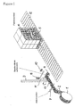
- the figures 1-4 show the structure of the device and the process of banding, ie the strapping of the product units.
- Fig. 1 shows a conveyor 12 with a pallet 5, on which stacked product units 6 are located.
- a light barrier is arranged (not shown), which detects the length of the product stack at the inlet of the pallet.
- the strip material 2 is withdrawn for strapping and according to the required length, d. H.
- the winding head 4 is arranged at a winding station 11 1, which in turn is located on a support arm 3, which depends on a gantry robot (not shown).
- the winding station 11 is rotatably connected to the support arm 3. After the cutting of the strip material 2, the winding head 4 is brought into a vertical position, wherein the flag 13 protrudes as a projection of this. Furthermore, the pivotable banderole holder 8 and the glue application station 10 are shown.
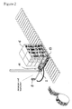
- FIG. 2 shows the stack of product units 6 delivered to the strapping position on the conveyor.
- the winding station 11 is suspended vertically from the support arm 3.
- the longitudinally standing flag 13 is gripped by the roll holder and placed against the product stack, the banderole holder initially remains in this position.
- the band end 9 stands over the banderole holder 8 with the flag 13 on. Thereafter, the gantry robot bypasses the pallet and wraps it with the strip material 2, as indicated in Fig. 3 .
- the glue application nozzles 10 apply glue to the lateral beginning of the strip and the winding station 11 is pressed against the lug 13. Thereafter, the banderole holder 8 is pivoted back and the portal robot pulls the band around the (in the illustration) rear side surface of the product stack 6 and glued the tape 2 to the beginning of the tape.
- Fig. 4 shows this situation. Subsequently, the glue nozzles move back. The pallet 5 is slowly moving out. In this case, the still fitting Banderolenhalter 8 presses the tape end 9 on the surface sprayed with glue. Thus, the band is connected at the ends. The banderole holder 8 moves to the basic position. The winding head 4 moves to receive the next banderole.
Landscapes
- Engineering & Computer Science (AREA)
- Mechanical Engineering (AREA)
- Basic Packing Technique (AREA)
Applications Claiming Priority (1)
| Application Number | Priority Date | Filing Date | Title |
|---|---|---|---|
| DE200610055991 DE102006055991A1 (de) | 2006-11-24 | 2006-11-24 | Banderolierer sowie Verfahren zum Banderolieren von Paletten |
Publications (1)
| Publication Number | Publication Date |
|---|---|
| EP1925554A1 true EP1925554A1 (fr) | 2008-05-28 |
Family
ID=38969333
Family Applications (1)
| Application Number | Title | Priority Date | Filing Date |
|---|---|---|---|
| EP07020959A Withdrawn EP1925554A1 (fr) | 2006-11-24 | 2007-10-26 | Dispositif d'application de bandes et procédé de bandage de palettes |
Country Status (2)
| Country | Link |
|---|---|
| EP (1) | EP1925554A1 (fr) |
| DE (1) | DE102006055991A1 (fr) |
Families Citing this family (3)
| Publication number | Priority date | Publication date | Assignee | Title |
|---|---|---|---|---|
| IT201800005364A1 (it) * | 2018-05-14 | 2019-11-14 | Macchina per realizzare un carico pallettizzato composto | |
| EP4458690A1 (fr) | 2023-05-05 | 2024-11-06 | Micha Augstein | Dispositif d'emballage, ensemble d'emballage et utilisation |
| DE202023105575U1 (de) | 2023-05-05 | 2024-08-06 | Micha Augstein | Verpackungseinrichtung, Verpackungsanordnung und Verwendung |
Citations (2)
| Publication number | Priority date | Publication date | Assignee | Title |
|---|---|---|---|---|
| GB1270051A (en) * | 1968-04-17 | 1972-04-12 | Reynolds Metals Co | Method of making a package |
| JPH09118386A (ja) * | 1995-10-25 | 1997-05-06 | Sanyo Electric Co Ltd | 冷凍機の梱包装置及び冷凍機の梱包方法 |
-
2006
- 2006-11-24 DE DE200610055991 patent/DE102006055991A1/de not_active Withdrawn
-
2007
- 2007-10-26 EP EP07020959A patent/EP1925554A1/fr not_active Withdrawn
Patent Citations (2)
| Publication number | Priority date | Publication date | Assignee | Title |
|---|---|---|---|---|
| GB1270051A (en) * | 1968-04-17 | 1972-04-12 | Reynolds Metals Co | Method of making a package |
| JPH09118386A (ja) * | 1995-10-25 | 1997-05-06 | Sanyo Electric Co Ltd | 冷凍機の梱包装置及び冷凍機の梱包方法 |
Also Published As
| Publication number | Publication date |
|---|---|
| DE102006055991A1 (de) | 2008-05-29 |
Similar Documents
| Publication | Publication Date | Title |
|---|---|---|
| DE19549664C2 (de) | Vorrichtung zum Verpacken einer Materialbahnrolle | |
| DE2451149C2 (de) | Vorrichtung zum Aufrollen und Zusammenpressen eines flexiblen, zusammendrückbaren Streifens | |
| DE2413807A1 (de) | Verfahren und vorrichtung zur herstellung von packungen mittels eines um das packgut herumgelegten bandes | |
| DE69309473T2 (de) | Verfahren zum verpacken von ladungen mittels einer streckfolie, maschine und folie zur ausübung des verfahrens | |
| DE102015012972A1 (de) | Klebeband-Applikator mit Spanneinrichtung | |
| EP0156012A1 (fr) | Procédé pour envelopper des marchandises empilées | |
| DE2724100A1 (de) | Verfahren und vorrichtung zum automatischen verpacken von stueckgut | |
| DE3641757C2 (de) | Verfahren und Vorrichtung zur Herstellung von Selbstklebezettelblöcken | |
| DE69917627T2 (de) | Verfahren und Maschine zum Verpacken von ringförmigen Strängen eines flexiblen länglichen Elements | |
| EP0427126B1 (fr) | Dispositif pour changer une bande | |
| WO1999042397A1 (fr) | Procede et dispositif pour l'introduction d'une pluralite de formes de presentation en feuilles individuelles dans un distributeur, avec formation d'une pile multicouche | |
| DE10057597A1 (de) | Vorrichtung zum Speichern und Abwickeln von Materialrollen in Buchbindereimaschinen | |
| DE4016484C2 (de) | Verpackungsvorrichtung für Bahnrollen | |
| DE3825861C2 (fr) | ||
| EP1925554A1 (fr) | Dispositif d'application de bandes et procédé de bandage de palettes | |
| EP1749590A2 (fr) | Procédé d'application d'adhésifs sur une liaison entre deux bandes et applicateur de ruban adhésif | |
| DE69312823T2 (de) | Automatische Wickelmaschine für bandartige Produkte | |
| EP1041025A2 (fr) | Procédé et dispositif pour préparer une bobine de papier pour le changement en continu de bobine | |
| DE102007008996A1 (de) | Produktrolle und Vorrichtung zum Herstellen einer solchen Produktrolle | |
| DE10139563B4 (de) | Vorrichtung und Verfahren zur Vorbereitung einer Vorratspapierbahnrolle für den fliegenden Rollenwechsel | |
| EP4662130A1 (fr) | Machine à emballer et procédé de production d'unités d'emballage | |
| DE3710639C2 (fr) | ||
| EP2082982B1 (fr) | Dispositif d'enroulement | |
| WO2009111809A1 (fr) | Procédé pour enrouler une bande de papier | |
| DE19752112C1 (de) | Rollenwickeleinrichtung |
Legal Events
| Date | Code | Title | Description |
|---|---|---|---|
| PUAI | Public reference made under article 153(3) epc to a published international application that has entered the european phase |
Free format text: ORIGINAL CODE: 0009012 |
|
| AK | Designated contracting states |
Kind code of ref document: A1 Designated state(s): AT BE BG CH CY CZ DE DK EE ES FI FR GB GR HU IE IS IT LI LT LU LV MC MT NL PL PT RO SE SI SK TR |
|
| AX | Request for extension of the european patent |
Extension state: AL BA HR MK RS |
|
| 17P | Request for examination filed |
Effective date: 20081128 |
|
| AKX | Designation fees paid |
Designated state(s): AT BE BG CH CY CZ DE DK EE ES FI FR GB GR HU IE IS IT LI LT LU LV MC MT NL PL PT RO SE SI SK TR |
|
| GRAP | Despatch of communication of intention to grant a patent |
Free format text: ORIGINAL CODE: EPIDOSNIGR1 |
|
| STAA | Information on the status of an ep patent application or granted ep patent |
Free format text: STATUS: THE APPLICATION IS DEEMED TO BE WITHDRAWN |
|
| 18D | Application deemed to be withdrawn |
Effective date: 20090729 |