EP1925493A2 - Energy management for hybrid energy railway vehicle - Google Patents
Energy management for hybrid energy railway vehicle Download PDFInfo
- Publication number
- EP1925493A2 EP1925493A2 EP07254556A EP07254556A EP1925493A2 EP 1925493 A2 EP1925493 A2 EP 1925493A2 EP 07254556 A EP07254556 A EP 07254556A EP 07254556 A EP07254556 A EP 07254556A EP 1925493 A2 EP1925493 A2 EP 1925493A2
- Authority
- EP
- European Patent Office
- Prior art keywords
- power
- vehicle
- electrical storage
- railway vehicle
- storage means
- Prior art date
- Legal status (The legal status is an assumption and is not a legal conclusion. Google has not performed a legal analysis and makes no representation as to the accuracy of the status listed.)
- Withdrawn
Links
- 238000007599 discharging Methods 0.000 claims description 6
- 238000010586 diagram Methods 0.000 description 10
- 230000001133 acceleration Effects 0.000 description 5
- 230000000694 effects Effects 0.000 description 1
- 238000012423 maintenance Methods 0.000 description 1
- 238000010248 power generation Methods 0.000 description 1
- 230000001172 regenerating effect Effects 0.000 description 1
- 230000008929 regeneration Effects 0.000 description 1
- 238000011069 regeneration method Methods 0.000 description 1
- 230000003068 static effect Effects 0.000 description 1
Images




Classifications
-
- B—PERFORMING OPERATIONS; TRANSPORTING
- B60—VEHICLES IN GENERAL
- B60L—PROPULSION OF ELECTRICALLY-PROPELLED VEHICLES; SUPPLYING ELECTRIC POWER FOR AUXILIARY EQUIPMENT OF ELECTRICALLY-PROPELLED VEHICLES; ELECTRODYNAMIC BRAKE SYSTEMS FOR VEHICLES IN GENERAL; MAGNETIC SUSPENSION OR LEVITATION FOR VEHICLES; MONITORING OPERATING VARIABLES OF ELECTRICALLY-PROPELLED VEHICLES; ELECTRIC SAFETY DEVICES FOR ELECTRICALLY-PROPELLED VEHICLES
- B60L1/00—Supplying electric power to auxiliary equipment of vehicles
- B60L1/003—Supplying electric power to auxiliary equipment of vehicles to auxiliary motors, e.g. for pumps, compressors
-
- B—PERFORMING OPERATIONS; TRANSPORTING
- B60—VEHICLES IN GENERAL
- B60L—PROPULSION OF ELECTRICALLY-PROPELLED VEHICLES; SUPPLYING ELECTRIC POWER FOR AUXILIARY EQUIPMENT OF ELECTRICALLY-PROPELLED VEHICLES; ELECTRODYNAMIC BRAKE SYSTEMS FOR VEHICLES IN GENERAL; MAGNETIC SUSPENSION OR LEVITATION FOR VEHICLES; MONITORING OPERATING VARIABLES OF ELECTRICALLY-PROPELLED VEHICLES; ELECTRIC SAFETY DEVICES FOR ELECTRICALLY-PROPELLED VEHICLES
- B60L50/00—Electric propulsion with power supplied within the vehicle
- B60L50/50—Electric propulsion with power supplied within the vehicle using propulsion power supplied by batteries or fuel cells
- B60L50/60—Electric propulsion with power supplied within the vehicle using propulsion power supplied by batteries or fuel cells using power supplied by batteries
- B60L50/61—Electric propulsion with power supplied within the vehicle using propulsion power supplied by batteries or fuel cells using power supplied by batteries by batteries charged by engine-driven generators, e.g. series hybrid electric vehicles
-
- B—PERFORMING OPERATIONS; TRANSPORTING
- B60—VEHICLES IN GENERAL
- B60L—PROPULSION OF ELECTRICALLY-PROPELLED VEHICLES; SUPPLYING ELECTRIC POWER FOR AUXILIARY EQUIPMENT OF ELECTRICALLY-PROPELLED VEHICLES; ELECTRODYNAMIC BRAKE SYSTEMS FOR VEHICLES IN GENERAL; MAGNETIC SUSPENSION OR LEVITATION FOR VEHICLES; MONITORING OPERATING VARIABLES OF ELECTRICALLY-PROPELLED VEHICLES; ELECTRIC SAFETY DEVICES FOR ELECTRICALLY-PROPELLED VEHICLES
- B60L58/00—Methods or circuit arrangements for monitoring or controlling batteries or fuel cells, specially adapted for electric vehicles
- B60L58/10—Methods or circuit arrangements for monitoring or controlling batteries or fuel cells, specially adapted for electric vehicles for monitoring or controlling batteries
- B60L58/18—Methods or circuit arrangements for monitoring or controlling batteries or fuel cells, specially adapted for electric vehicles for monitoring or controlling batteries of two or more battery modules
- B60L58/20—Methods or circuit arrangements for monitoring or controlling batteries or fuel cells, specially adapted for electric vehicles for monitoring or controlling batteries of two or more battery modules having different nominal voltages
-
- B—PERFORMING OPERATIONS; TRANSPORTING
- B60—VEHICLES IN GENERAL
- B60L—PROPULSION OF ELECTRICALLY-PROPELLED VEHICLES; SUPPLYING ELECTRIC POWER FOR AUXILIARY EQUIPMENT OF ELECTRICALLY-PROPELLED VEHICLES; ELECTRODYNAMIC BRAKE SYSTEMS FOR VEHICLES IN GENERAL; MAGNETIC SUSPENSION OR LEVITATION FOR VEHICLES; MONITORING OPERATING VARIABLES OF ELECTRICALLY-PROPELLED VEHICLES; ELECTRIC SAFETY DEVICES FOR ELECTRICALLY-PROPELLED VEHICLES
- B60L2200/00—Type of vehicles
- B60L2200/26—Rail vehicles
-
- B—PERFORMING OPERATIONS; TRANSPORTING
- B60—VEHICLES IN GENERAL
- B60L—PROPULSION OF ELECTRICALLY-PROPELLED VEHICLES; SUPPLYING ELECTRIC POWER FOR AUXILIARY EQUIPMENT OF ELECTRICALLY-PROPELLED VEHICLES; ELECTRODYNAMIC BRAKE SYSTEMS FOR VEHICLES IN GENERAL; MAGNETIC SUSPENSION OR LEVITATION FOR VEHICLES; MONITORING OPERATING VARIABLES OF ELECTRICALLY-PROPELLED VEHICLES; ELECTRIC SAFETY DEVICES FOR ELECTRICALLY-PROPELLED VEHICLES
- B60L2210/00—Converter types
- B60L2210/20—AC to AC converters
-
- Y—GENERAL TAGGING OF NEW TECHNOLOGICAL DEVELOPMENTS; GENERAL TAGGING OF CROSS-SECTIONAL TECHNOLOGIES SPANNING OVER SEVERAL SECTIONS OF THE IPC; TECHNICAL SUBJECTS COVERED BY FORMER USPC CROSS-REFERENCE ART COLLECTIONS [XRACs] AND DIGESTS
- Y02—TECHNOLOGIES OR APPLICATIONS FOR MITIGATION OR ADAPTATION AGAINST CLIMATE CHANGE
- Y02T—CLIMATE CHANGE MITIGATION TECHNOLOGIES RELATED TO TRANSPORTATION
- Y02T10/00—Road transport of goods or passengers
- Y02T10/60—Other road transportation technologies with climate change mitigation effect
- Y02T10/62—Hybrid vehicles
-
- Y—GENERAL TAGGING OF NEW TECHNOLOGICAL DEVELOPMENTS; GENERAL TAGGING OF CROSS-SECTIONAL TECHNOLOGIES SPANNING OVER SEVERAL SECTIONS OF THE IPC; TECHNICAL SUBJECTS COVERED BY FORMER USPC CROSS-REFERENCE ART COLLECTIONS [XRACs] AND DIGESTS
- Y02—TECHNOLOGIES OR APPLICATIONS FOR MITIGATION OR ADAPTATION AGAINST CLIMATE CHANGE
- Y02T—CLIMATE CHANGE MITIGATION TECHNOLOGIES RELATED TO TRANSPORTATION
- Y02T10/00—Road transport of goods or passengers
- Y02T10/60—Other road transportation technologies with climate change mitigation effect
- Y02T10/70—Energy storage systems for electromobility, e.g. batteries
-
- Y—GENERAL TAGGING OF NEW TECHNOLOGICAL DEVELOPMENTS; GENERAL TAGGING OF CROSS-SECTIONAL TECHNOLOGIES SPANNING OVER SEVERAL SECTIONS OF THE IPC; TECHNICAL SUBJECTS COVERED BY FORMER USPC CROSS-REFERENCE ART COLLECTIONS [XRACs] AND DIGESTS
- Y02—TECHNOLOGIES OR APPLICATIONS FOR MITIGATION OR ADAPTATION AGAINST CLIMATE CHANGE
- Y02T—CLIMATE CHANGE MITIGATION TECHNOLOGIES RELATED TO TRANSPORTATION
- Y02T10/00—Road transport of goods or passengers
- Y02T10/60—Other road transportation technologies with climate change mitigation effect
- Y02T10/72—Electric energy management in electromobility
Definitions
- the present invention relates to a drive control device for railway vehicle and particularly to a control device provided with power generating means and electrical storage means and driving a railway vehicle using electric power generated by the both means.
- FIG. 6 is a diagram illustrating configuration of a conventional example of a hybrid railway vehicle.
- a railway vehicle 201 comprises power generating means 202 driven by an engine and generating AC power, power converting means 205 for converting the AC power to DC power and moreover to the AC power again for driving a wheel 206 directly connected to a motor, and electrical storage means 204 having functions for charging and discharging the DC power of the power converting means 205.
- Optimal power management is carried out for the power generating means 202, the power converting means 205, and the electrical storage means 204 by control means 203.
- Patent Document 1 discloses such a hybrid railway vehicle.
- an auxiliary power supply device for supplying power to an air conditioner, an in-vehicle fluorescent lamp, an air compressor and the like (hereinafter referred to as SIV (Static Inverter)) is mounted.
- SIV Static Inverter
- the SIC is also a system configured to convert the DC power to the AC power similarly to the power converting means 205 shown in FIG. 6 and is a device that outputs an AC current of 60 Hz at 440 V or 200 V and keeps on supplying a constant power continuously from when the railway vehicle leaves a rail yard till when it finishes service and enters the yard again.
- the power converter 205 has a difference in that a large power at acceleration of the vehicle is supplied for driving vehicle, while a large power is regenerated at deceleration, and since the power converting means 205 does not operate during the vehicle is waiting, the power generating means 202 might be stopped.
- Power should be continuously supplied to the SIC even in this case, and if even the SIC is to be driven by the electrical storage means 204, there can be nonconformity that optimal power management can not be realized at restart of the vehicle or the like.
- the present invention was made in view of the above circumstances and has an object to provide a drive control device for railway vehicle for optically managing power of electrical storage means not only in driving but also during waiting.
- the above object can be achieved by providing first electrical storage means at power converting means that supplies power to a motor for driving a vehicle and by providing second electrical storage means at power means that supplies power to an auxiliary power supply device for vehicle, in which the first electrical storage means and the second electrical storage means are connected to each other by power level converting means so that power is exchanged between the first electrical storage means and the second electrical storage means via the power level converting means according to a driving state of the vehicle.
- electrical storage means suitable for each of the driving control device for vehicle and the auxiliary power supply device for vehicle can be prepared, respectively, and optimal power management is realized. Also, through exchange of power, it is advantageous that power supply assistance can be made from one electrical storage means to the other electrical storage means, and vehicle performance can be also improved.
- FIG. 1 is an explanatory diagram of a driving control device for railway vehicle in a first embodiment of the present invention.
- a power generator 3 is directly connected to an engine 2, and by driving the engine 2, the power generator 3 generates AC power.
- the AC power is fed to a converter 4 and converted to DC power.
- a storage battery A1 and an inverter 5 are connected so as to convert the DC power Ed1 to the AC power again, and the AC power drives motors 21 and 22.
- one of a step-up/down chopper 8 is connected, while to the other of the step-up/down chopper 8, a storage battery B6 and an auxiliary power supply device 7 for vehicle are connected so as to convert the DC power Ed2 to the AC power and to supply the AC power to a load 23.
- the output power of the engine 2 is controlled by an output 42 of an engine control device 12, the converter 4 by an output 43 of a converter control device 13, a storage battery A1 by an output 41 of a storage battery A control device 11, and the inverter 5 by an output 44 of an inverter control device 14, respectively, with regard to driving control of the vehicle.
- the storage battery B6 is controlled by an output 45 of a storage battery B control device 15, the auxiliary power supply device 7 for vehicle by an output 46 of an SIV control device 16, with regard to control to supply power with constant voltage to the load such as a fluorescent lamp and an air conditioner in a vehicle.
- the above engine control device 12, the converter control device 13, the storage battery A control device 11, the inverter control device 14, the storage battery B control device 15, and the SIV control device 16 are given appropriate power management of Ed1, Ed2 by a general control device 9.
- FIG. 2 explains characteristics of each storage battery in an embodiment of the present invention.
- the storage battery A supplies a large power to the inverter 5 at acceleration of the vehicle, while a regenerative electric power is supplied from the inverter 5 at deceleration.
- FIG. 2 input/output of a storage battery with respect to a storage amount needs a symmetric characteristic. In other words, a type of storage battery with a high output in a short time is required.
- the storage battery B needs substantially constant input/output characteristics as shown in FIG. 2 since the vehicle auxiliary power supply device (SIV) 7 continuously supplies a constant voltage to the load 23.
- the vehicle auxiliary power supply device (SIV) 7 continuously supplies a constant voltage to the load 23.
- the storage battery A is used for the storage battery B, when the engine is stopped during the vehicle is waiting in respect of noise/energy saving, discharging is expedited, which causes trouble in power supply to the vehicle auxiliary power supply device (SIV) 7.
- the storage battery B is used for the storage battery A, a large power required for driving of the vehicle can not be supplied, which hinders operation of the vehicle. Therefore, it is important to choose a storage battery with a characteristic according to use of the power converting means of a railway vehicle.
- FIG. 3 explains an action of a step-up/down chopper at acceleration driving in the embodiment of the present invention.
- the step-up/down chopper 8 is an important component in the hybrid railway vehicle using storage batteries with different characteristics as above. In acceleration of the vehicle, it is operated as a step-up chopper as shown in FIG. 3 , power 152 from the storage battery B6 is supplied to the inverter 5 via a step-up chopper 81 so that power 151 from the storage battery A1 can be assisted.
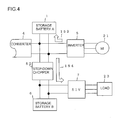
- FIG. 4 is an action explanatory diagram of a step-down chopper at deceleration driving of a vehicle in the embodiment of the present invention.
- the step-down chopper 82 is operated according to the size of the DC voltage of the inverter 5 so as to operate as the step-down chopper 82 so that power 154 to the vehicle auxiliary power supply device (SIV) 7 can be assisted.
- SIV vehicle auxiliary power supply device
- FIG. 5 is an action explanatory diagram of the step-down chopper during the vehicle is waiting in the first embodiment of the present invention.
- the step-down chopper 82 is operated so as to supply power 161 of the storage battery A1 to the vehicle auxiliary power supply device (SIV) 7 through the step-down chopper 82 so that and power 162 from the storage battery B6 can be assisted.
- SIV vehicle auxiliary power supply device
- the chopper control device 18 controlling the step-up/down chopper 8 is connected to the general control device 9 as shown in FIG. 1 , and the driving state of each of the engine 2, the converter 4, the inverter 5, and the vehicle auxiliary power supply device 7 and the charging/discharging state of the storage battery A1 and the storage battery B6 can be known, which enables optimal power assistance.
- the optimal power management is realized, and vehicle performance can be improved.
Landscapes
- Engineering & Computer Science (AREA)
- Power Engineering (AREA)
- Transportation (AREA)
- Mechanical Engineering (AREA)
- Life Sciences & Earth Sciences (AREA)
- Sustainable Development (AREA)
- Sustainable Energy (AREA)
- Electric Propulsion And Braking For Vehicles (AREA)
Abstract
Description
- The present invention relates to a drive control device for railway vehicle and particularly to a control device provided with power generating means and electrical storage means and driving a railway vehicle using electric power generated by the both means.
- There are many non-electrified lines in local railway lines with a few services, where passenger transportation by railway motor cars powered by diesel engine is utilized in general. Recently, application of a so-called hybrid railway vehicle to the non-electrified lines is being examined, using also electrical storage means in power generation equipment driven by an engine for which effects of reduction in maintenance works and moreover of exhaust gas reduction can be expected.
-
FIG. 6 is a diagram illustrating configuration of a conventional example of a hybrid railway vehicle. Arailway vehicle 201 comprises power generating means 202 driven by an engine and generating AC power, power converting means 205 for converting the AC power to DC power and moreover to the AC power again for driving awheel 206 directly connected to a motor, and electrical storage means 204 having functions for charging and discharging the DC power of the power converting means 205. Optimal power management is carried out for the power generating means 202, the power converting means 205, and the electrical storage means 204 by control means 203. For example,Japanese Patent Laid-Open Publication No. 2005-27447 - On a railway vehicle, an auxiliary power supply device for supplying power to an air conditioner, an in-vehicle fluorescent lamp, an air compressor and the like (hereinafter referred to as SIV (Static Inverter)) is mounted.
- The SIC is also a system configured to convert the DC power to the AC power similarly to the power converting means 205 shown in
FIG. 6 and is a device that outputs an AC current of 60 Hz at 440 V or 200 V and keeps on supplying a constant power continuously from when the railway vehicle leaves a rail yard till when it finishes service and enters the yard again. - On the other hand, the
power converter 205 has a difference in that a large power at acceleration of the vehicle is supplied for driving vehicle, while a large power is regenerated at deceleration, and since thepower converting means 205 does not operate during the vehicle is waiting, thepower generating means 202 might be stopped. - Power should be continuously supplied to the SIC even in this case, and if even the SIC is to be driven by the electrical storage means 204, there can be nonconformity that optimal power management can not be realized at restart of the vehicle or the like.
- The present invention was made in view of the above circumstances and has an object to provide a drive control device for railway vehicle for optically managing power of electrical storage means not only in driving but also during waiting.
- The above object can be achieved by providing first electrical storage means at power converting means that supplies power to a motor for driving a vehicle and by providing second electrical storage means at power means that supplies power to an auxiliary power supply device for vehicle, in which the first electrical storage means and the second electrical storage means are connected to each other by power level converting means so that power is exchanged between the first electrical storage means and the second electrical storage means via the power level converting means according to a driving state of the vehicle.
- According to the present invention, electrical storage means suitable for each of the driving control device for vehicle and the auxiliary power supply device for vehicle can be prepared, respectively, and optimal power management is realized. Also, through exchange of power, it is advantageous that power supply assistance can be made from one electrical storage means to the other electrical storage means, and vehicle performance can be also improved.
-
-
FIG. 1 is an explanatory diagram of a driving control device for a railway vehicle in an embodiment of the present invention; -
FIG. 2 is an explanatory diagram of each storage battery of the embodiment of the present invention; -
FIG. 3 is an action explanatory diagram of a step-up chopper at acceleration driving of a vehicle in the embodiment of the present invention; -
FIG. 4 is an action explanatory diagram of a step-down chopper at deceleration driving of a vehicle in the embodiment of the present invention; -
FIG. 5 is an action explanatory diagram of the step-down chopper at waiting of the vehicle in the first embodiment of the present invention; and -
FIG. 6 is an explanatory diagram of configuration of a hybrid energy railway vehicle in a conventional example. - An embodiment of the present invention will be described below referring to the attached drawings.
-
FIG. 1 is an explanatory diagram of a driving control device for railway vehicle in a first embodiment of the present invention. InFIG. 1 , apower generator 3 is directly connected to anengine 2, and by driving theengine 2, thepower generator 3 generates AC power. The AC power is fed to aconverter 4 and converted to DC power. To an output Ed1 of theconverter 4, a storage battery A1 and aninverter 5 are connected so as to convert the DC power Ed1 to the AC power again, and the ACpower drives motors converter 4, one of a step-up/downchopper 8 is connected, while to the other of the step-up/downchopper 8, a storage battery B6 and an auxiliarypower supply device 7 for vehicle are connected so as to convert the DC power Ed2 to the AC power and to supply the AC power to aload 23. - The output power of the
engine 2 is controlled by an output 42 of an engine control device 12, theconverter 4 by an output 43 of a converter control device 13, a storage battery A1 by an output 41 of a storage battery A control device 11, and theinverter 5 by an output 44 of an inverter control device 14, respectively, with regard to driving control of the vehicle. - The storage battery B6 is controlled by an output 45 of a storage battery B control device 15, the auxiliary
power supply device 7 for vehicle by an output 46 of an SIV control device 16, with regard to control to supply power with constant voltage to the load such as a fluorescent lamp and an air conditioner in a vehicle. - The above engine control device 12, the converter control device 13, the storage battery A control device 11, the inverter control device 14, the storage battery B control device 15, and the SIV control device 16 are given appropriate power management of Ed1, Ed2 by a
general control device 9. -
FIG. 2 explains characteristics of each storage battery in an embodiment of the present invention. - As charging/discharging characteristics of storage batteries in a hybrid energy railway vehicle in
FIG. 1 , the storage battery A supplies a large power to theinverter 5 at acceleration of the vehicle, while a regenerative electric power is supplied from theinverter 5 at deceleration. Thus, as shown inFIG. 2 , input/output of a storage battery with respect to a storage amount needs a symmetric characteristic. In other words, a type of storage battery with a high output in a short time is required. - On the other hand, the storage battery B needs substantially constant input/output characteristics as shown in
FIG. 2 since the vehicle auxiliary power supply device (SIV) 7 continuously supplies a constant voltage to theload 23. - If the storage battery A is used for the storage battery B, when the engine is stopped during the vehicle is waiting in respect of noise/energy saving, discharging is expedited, which causes trouble in power supply to the vehicle auxiliary power supply device (SIV) 7. On the other hand, if the storage battery B is used for the storage battery A, a large power required for driving of the vehicle can not be supplied, which hinders operation of the vehicle. Therefore, it is important to choose a storage battery with a characteristic according to use of the power converting means of a railway vehicle.
-
FIG. 3 explains an action of a step-up/down chopper at acceleration driving in the embodiment of the present invention. The step-up/downchopper 8 is an important component in the hybrid railway vehicle using storage batteries with different characteristics as above. In acceleration of the vehicle, it is operated as a step-up chopper as shown inFIG. 3 , power 152 from the storage battery B6 is supplied to theinverter 5 via a step-up chopper 81 so that power 151 from the storage battery A1 can be assisted. -
FIG. 4 is an action explanatory diagram of a step-down chopper at deceleration driving of a vehicle in the embodiment of the present invention. In power regeneration at deceleration of the vehicle, as shown inFIG. 4 , in addition to power 153 for charging the storage battery A1, the step-down chopper 82 is operated according to the size of the DC voltage of theinverter 5 so as to operate as the step-down chopper 82 so that power 154 to the vehicle auxiliary power supply device (SIV) 7 can be assisted. -
FIG. 5 is an action explanatory diagram of the step-down chopper during the vehicle is waiting in the first embodiment of the present invention. - In
FIG. 5 , even if the vehicle stops the engine during waiting, the step-down chopper 82 is operated so as to supply power 161 of the storage battery A1 to the vehicle auxiliary power supply device (SIV) 7 through the step-down chopper 82 so that and power 162 from the storage battery B6 can be assisted. - The
chopper control device 18 controlling the step-up/downchopper 8 is connected to thegeneral control device 9 as shown inFIG. 1 , and the driving state of each of theengine 2, theconverter 4, theinverter 5, and the vehicle auxiliarypower supply device 7 and the charging/discharging state of the storage battery A1 and the storage battery B6 can be known, which enables optimal power assistance. - With the embodiment as mentioned above, the optimal power management is realized, and vehicle performance can be improved.
Claims (4)
- A drive control device for railway vehicle in a railway vehicle driving system on which power generating means by an engine, DC power generating means having converter means that converts AC power generated by the power generating means to first DC power, first AC power generating means having inverter means that inverts the first DC power to first AC power, first electrical storage means having functions of charging and discharging the first DC power, control means that controls the power generating means, the DC power generating means, the first AC power generating means, and the first DC electrical storage means, and a driving motor driven by the first AC power are mounted, characterized by comprising:second electrical storage means having a function of charging and discharging second DC power with a level different from the first DC power, second AC power generating means having inverter means that inverts the second DC power to second AC power, power level converting means between the first DC power and second DC power, and a control means that controls the power level converting means.
- The drive control device for railway vehicle according to claim 1, characterized in that
the power level converting means between the first DC power and second DC power supplies the second DC power to the first AC power generating means or supplies the first DC power to the second AC power generating means according to the state of the first DC power and the second DC power. - The drive control device for railway vehicle according to claim 2, characterized in that
the first DC power is supplied to the second DC power through the power level converting means during waiting of the railway vehicle. - The drive control device for railway vehicle according to claim 2, characterized in that the second DC power is supplied to the first DC power through the power level converting means during driving of the railway vehicle.
Applications Claiming Priority (1)
| Application Number | Priority Date | Filing Date | Title |
|---|---|---|---|
| JP2006317369A JP4417948B2 (en) | 2006-11-24 | 2006-11-24 | Railway vehicle drive control device |
Publications (2)
| Publication Number | Publication Date |
|---|---|
| EP1925493A2 true EP1925493A2 (en) | 2008-05-28 |
| EP1925493A3 EP1925493A3 (en) | 2010-08-04 |
Family
ID=39183089
Family Applications (1)
| Application Number | Title | Priority Date | Filing Date |
|---|---|---|---|
| EP07254556A Withdrawn EP1925493A3 (en) | 2006-11-24 | 2007-11-22 | Energy management for hybrid energy railway vehicle |
Country Status (3)
| Country | Link |
|---|---|
| EP (1) | EP1925493A3 (en) |
| JP (1) | JP4417948B2 (en) |
| CN (1) | CN101186184B (en) |
Cited By (10)
| Publication number | Priority date | Publication date | Assignee | Title |
|---|---|---|---|---|
| WO2011098542A1 (en) * | 2010-02-11 | 2011-08-18 | Gottwald Port Technology Gmbh | Crane, in particular mobile port crane, comprising a hybrid drive system |
| ITBO20100407A1 (en) * | 2010-06-24 | 2011-12-25 | Ferrari Spa | ELECTRICAL POWER PLANT OF A VEHICLE WITH ELECTRIC PROPULSION |
| JP2012205495A (en) * | 2011-03-23 | 2012-10-22 | General Electric Co <Ge> | System for supplying propulsion energy from auxiliary driving part and production method thereof |
| CN103458656A (en) * | 2013-08-01 | 2013-12-18 | 深圳市英威腾交通技术有限公司 | Auxiliary power box |
| EP2189322A3 (en) * | 2008-11-20 | 2014-08-27 | Hitachi Ltd. | Storage battery system, monitoring device and hybrid railway vehicle |
| EP2431215A4 (en) * | 2009-05-14 | 2016-11-02 | Toyota Motor Co Ltd | ELECTRIC CAR AND ITS CONTROL METHOD |
| EP2566008A3 (en) * | 2011-08-31 | 2017-08-30 | Kabushiki Kaisha Toshiba | Battery charging system and train |
| DE102017129255B3 (en) | 2017-12-08 | 2018-09-20 | Bombardier Transportation Gmbh | Control system and method for controlling a rail vehicle |
| US10086703B2 (en) | 2014-12-31 | 2018-10-02 | General Electric Company | System and method for controlling electrically driven accessories |
| US20220242275A1 (en) * | 2021-02-04 | 2022-08-04 | Volvo Truck Corporation | Electromobility system for a vehicle |
Families Citing this family (13)
| Publication number | Priority date | Publication date | Assignee | Title |
|---|---|---|---|---|
| JP5366612B2 (en) | 2008-05-20 | 2013-12-11 | 株式会社東芝 | Image processing apparatus, image processing method, and image processing program |
| KR101082001B1 (en) | 2009-06-10 | 2011-11-09 | 한국철도기술연구원 | Control method of hybrid eletric railway car |
| US20120253604A1 (en) * | 2009-12-17 | 2012-10-04 | Renault Trucks | Steering motors power supply method and power supply system adapted to such a method |
| JP5801999B2 (en) * | 2010-08-24 | 2015-10-28 | 株式会社日立製作所 | Train trains equipped with railway on-board electrical equipment |
| CN101973276B (en) * | 2010-10-18 | 2012-11-28 | 宝鸡南车时代工程机械有限公司 | Alternating current drive fast track car |
| JP5298152B2 (en) | 2011-03-07 | 2013-09-25 | 株式会社日立製作所 | Power conversion device and power conversion device for railway vehicles |
| JP6080507B2 (en) * | 2012-11-07 | 2017-02-15 | 株式会社日立製作所 | Railway vehicle drive system |
| JP6184090B2 (en) * | 2012-12-12 | 2017-08-23 | 日本貨物鉄道株式会社 | Hybrid electric vehicle power supply system |
| DE102013008420A1 (en) * | 2013-05-17 | 2014-11-20 | Abb Technology Ag | Drive unit for controlling a motor |
| CN103358921A (en) * | 2013-07-26 | 2013-10-23 | 南车戚墅堰机车有限公司 | Novel alternating current transmission system for internal combustion locomotive |
| JP6829069B2 (en) * | 2016-12-28 | 2021-02-10 | 株式会社東芝 | Circuit system for railroad vehicles |
| CN109488468B (en) * | 2019-01-08 | 2021-02-05 | 中车株洲电力机车有限公司 | Control method, device, medium and equipment for output power of double internal combustion engine sets |
| JP7480416B2 (en) * | 2021-03-02 | 2024-05-09 | 株式会社日立製作所 | Railroad vehicle drive system and railroad vehicle drive method |
Citations (1)
| Publication number | Priority date | Publication date | Assignee | Title |
|---|---|---|---|---|
| JP2005027447A (en) | 2003-07-03 | 2005-01-27 | Hitachi Ltd | Railway vehicle drive system |
Family Cites Families (5)
| Publication number | Priority date | Publication date | Assignee | Title |
|---|---|---|---|---|
| DE4311230C2 (en) * | 1993-04-02 | 1996-12-19 | Mannesmann Ag | Non-track-bound vehicle with an electric motor |
| US6308639B1 (en) * | 2000-04-26 | 2001-10-30 | Railpower Technologies Corp. | Hybrid battery/gas turbine locomotive |
| JP4053289B2 (en) * | 2001-12-12 | 2008-02-27 | 本田技研工業株式会社 | Storage battery temperature control device and vehicle device using the same |
| CA2556831A1 (en) * | 2004-03-04 | 2005-09-15 | Tm4 Inc. | System and method for starting a combustion engine of a hybrid vehicle. |
| US7689330B2 (en) * | 2004-12-01 | 2010-03-30 | Ise Corporation | Method of controlling engine stop-start operation for heavy-duty hybrid-electric and hybrid-hydraulic vehicles |
-
2006
- 2006-11-24 JP JP2006317369A patent/JP4417948B2/en not_active Expired - Fee Related
-
2007
- 2007-11-22 EP EP07254556A patent/EP1925493A3/en not_active Withdrawn
- 2007-11-26 CN CN2007101940090A patent/CN101186184B/en not_active Expired - Fee Related
Patent Citations (1)
| Publication number | Priority date | Publication date | Assignee | Title |
|---|---|---|---|---|
| JP2005027447A (en) | 2003-07-03 | 2005-01-27 | Hitachi Ltd | Railway vehicle drive system |
Cited By (15)
| Publication number | Priority date | Publication date | Assignee | Title |
|---|---|---|---|---|
| EP2189322A3 (en) * | 2008-11-20 | 2014-08-27 | Hitachi Ltd. | Storage battery system, monitoring device and hybrid railway vehicle |
| EP2431215A4 (en) * | 2009-05-14 | 2016-11-02 | Toyota Motor Co Ltd | ELECTRIC CAR AND ITS CONTROL METHOD |
| WO2011098542A1 (en) * | 2010-02-11 | 2011-08-18 | Gottwald Port Technology Gmbh | Crane, in particular mobile port crane, comprising a hybrid drive system |
| US9056752B2 (en) | 2010-02-11 | 2015-06-16 | Terex Mhps Gmbh | Crane, in particular mobile port crane, comprising a hybrid drive system |
| ITBO20100407A1 (en) * | 2010-06-24 | 2011-12-25 | Ferrari Spa | ELECTRICAL POWER PLANT OF A VEHICLE WITH ELECTRIC PROPULSION |
| JP2012205495A (en) * | 2011-03-23 | 2012-10-22 | General Electric Co <Ge> | System for supplying propulsion energy from auxiliary driving part and production method thereof |
| EP2566008A3 (en) * | 2011-08-31 | 2017-08-30 | Kabushiki Kaisha Toshiba | Battery charging system and train |
| CN103458656A (en) * | 2013-08-01 | 2013-12-18 | 深圳市英威腾交通技术有限公司 | Auxiliary power box |
| CN103458656B (en) * | 2013-08-01 | 2017-03-01 | 深圳市英威腾交通技术有限公司 | A kind of auxiliary power box |
| US10086703B2 (en) | 2014-12-31 | 2018-10-02 | General Electric Company | System and method for controlling electrically driven accessories |
| EA038457B1 (en) * | 2014-12-31 | 2021-08-31 | ТРАНСПОРТЕЙШН АйПи ХОЛДИНГС, ЛЛС | System and method for controlling electrically driven accessories |
| DE102017129255B3 (en) | 2017-12-08 | 2018-09-20 | Bombardier Transportation Gmbh | Control system and method for controlling a rail vehicle |
| EP3498525A1 (en) | 2017-12-08 | 2019-06-19 | Bombardier Transportation GmbH | Control system and method for controlling a rail vehicle |
| US20220242275A1 (en) * | 2021-02-04 | 2022-08-04 | Volvo Truck Corporation | Electromobility system for a vehicle |
| US11667213B2 (en) * | 2021-02-04 | 2023-06-06 | Volvo Truck Corporation | Electromobility system for a vehicle |
Also Published As
| Publication number | Publication date |
|---|---|
| JP2008131834A (en) | 2008-06-05 |
| CN101186184B (en) | 2010-12-01 |
| EP1925493A3 (en) | 2010-08-04 |
| CN101186184A (en) | 2008-05-28 |
| JP4417948B2 (en) | 2010-02-17 |
Similar Documents
| Publication | Publication Date | Title |
|---|---|---|
| JP4417948B2 (en) | Railway vehicle drive control device | |
| US7723932B2 (en) | Propulsion system | |
| US8001906B2 (en) | Electric drive vehicle retrofit system and associated method | |
| US20060232238A1 (en) | Battery charging system for hybrid electric vehicles | |
| CN102015353B (en) | Multiple engine hybrid locomotive | |
| US8761978B2 (en) | System for supplying propulsion energy from an auxiliary drive and method of making same | |
| US9073448B2 (en) | Method of operating propulsion system | |
| JP6907175B2 (en) | Power system | |
| EP1724147A2 (en) | Control apparatus for an electric locomotive | |
| KR20190059060A (en) | Fuel cell vehicle system and control method of the same | |
| JP5097687B2 (en) | Railway vehicle and driving device for railway vehicle | |
| US8047317B2 (en) | System, vehicle, and method | |
| IT202000002566A1 (en) | ELECTRIC DRIVE VEHICLE INCLUDING AN ENERGY MANAGEMENT SYSTEM, AND METHOD OF ENERGY MANAGEMENT IN SUCH ELECTRIC DRIVE VEHICLE | |
| KR20080054281A (en) | Power down control method of fuel cell hybrid electric vehicle | |
| JP2012065521A (en) | Drive system of railway vehicle | |
| EP2636556A1 (en) | Train car system control device | |
| JP3886940B2 (en) | Control device for hybrid vehicle | |
| WO2013021486A1 (en) | Vehicle control device and diesel hybrid vehicle system | |
| JP7480416B2 (en) | Railroad vehicle drive system and railroad vehicle drive method | |
| JP5246941B2 (en) | Hybrid train | |
| US20150225000A1 (en) | Propulsion control device of hybrid vehicle | |
| JP2006340464A (en) | Electric car | |
| JP4830448B2 (en) | Vehicle drive system | |
| JP2004336833A (en) | Control device for power converter for railway vehicles | |
| JP2008042980A (en) | Railway vehicle drive control device |
Legal Events
| Date | Code | Title | Description |
|---|---|---|---|
| PUAI | Public reference made under article 153(3) epc to a published international application that has entered the european phase |
Free format text: ORIGINAL CODE: 0009012 |
|
| 17P | Request for examination filed |
Effective date: 20071211 |
|
| AK | Designated contracting states |
Kind code of ref document: A2 Designated state(s): AT BE BG CH CY CZ DE DK EE ES FI FR GB GR HU IE IS IT LI LT LU LV MC MT NL PL PT RO SE SI SK TR |
|
| AX | Request for extension of the european patent |
Extension state: AL BA HR MK RS |
|
| PUAL | Search report despatched |
Free format text: ORIGINAL CODE: 0009013 |
|
| AK | Designated contracting states |
Kind code of ref document: A3 Designated state(s): AT BE BG CH CY CZ DE DK EE ES FI FR GB GR HU IE IS IT LI LT LU LV MC MT NL PL PT RO SE SI SK TR |
|
| AX | Request for extension of the european patent |
Extension state: AL BA HR MK RS |
|
| RIC1 | Information provided on ipc code assigned before grant |
Ipc: B60L 1/00 20060101ALI20100629BHEP Ipc: B60L 11/18 20060101ALI20100629BHEP Ipc: B60L 11/12 20060101AFI20080401BHEP |
|
| AKX | Designation fees paid |
Designated state(s): AT BE BG CH CY CZ DE DK EE ES FI FR GB GR HU IE IS IT LI LT LU LV MC MT NL PL PT RO SE SI SK TR |
|
| STAA | Information on the status of an ep patent application or granted ep patent |
Free format text: STATUS: THE APPLICATION HAS BEEN WITHDRAWN |
|
| 18W | Application withdrawn |
Effective date: 20150729 |