EP1925442A1 - high performance moulding method and apparatus in a rotative path - Google Patents
high performance moulding method and apparatus in a rotative path Download PDFInfo
- Publication number
- EP1925442A1 EP1925442A1 EP06024451A EP06024451A EP1925442A1 EP 1925442 A1 EP1925442 A1 EP 1925442A1 EP 06024451 A EP06024451 A EP 06024451A EP 06024451 A EP06024451 A EP 06024451A EP 1925442 A1 EP1925442 A1 EP 1925442A1
- Authority
- EP
- European Patent Office
- Prior art keywords
- die
- displacement
- der
- grid
- tool
- Prior art date
- Legal status (The legal status is an assumption and is not a legal conclusion. Google has not performed a legal analysis and makes no representation as to the accuracy of the status listed.)
- Withdrawn
Links
Images


Classifications
-
- B—PERFORMING OPERATIONS; TRANSPORTING
- B30—PRESSES
- B30B—PRESSES IN GENERAL
- B30B11/00—Presses specially adapted for forming shaped articles from material in particulate or plastic state, e.g. briquetting presses, tabletting presses
- B30B11/02—Presses specially adapted for forming shaped articles from material in particulate or plastic state, e.g. briquetting presses, tabletting presses using a ram exerting pressure on the material in a moulding space
- B30B11/14—Presses specially adapted for forming shaped articles from material in particulate or plastic state, e.g. briquetting presses, tabletting presses using a ram exerting pressure on the material in a moulding space co-operating with moulds on a movable carrier other than a turntable or a rotating drum
-
- B—PERFORMING OPERATIONS; TRANSPORTING
- B30—PRESSES
- B30B—PRESSES IN GENERAL
- B30B15/00—Details of, or accessories for, presses; Auxiliary measures in connection with pressing
- B30B15/0082—Dust eliminating means; Mould or press ram cleaning means
-
- B—PERFORMING OPERATIONS; TRANSPORTING
- B30—PRESSES
- B30B—PRESSES IN GENERAL
- B30B15/00—Details of, or accessories for, presses; Auxiliary measures in connection with pressing
- B30B15/30—Feeding material to presses
- B30B15/302—Feeding material in particulate or plastic state to moulding presses
- B30B15/304—Feeding material in particulate or plastic state to moulding presses by using feed frames or shoes with relative movement with regard to the mould or moulds
- B30B15/306—Feeding material in particulate or plastic state to moulding presses by using feed frames or shoes with relative movement with regard to the mould or moulds for multi-layer articles
-
- B—PERFORMING OPERATIONS; TRANSPORTING
- B30—PRESSES
- B30B—PRESSES IN GENERAL
- B30B15/00—Details of, or accessories for, presses; Auxiliary measures in connection with pressing
- B30B15/34—Heating or cooling presses or parts thereof
Definitions
- the present invention relates to an apparatus for forming moldings from a moldable mass.
- the device comprises a die grid, in which at least one receiving space formed by side boundaries is formed, and at least one tool, with which the moldable mass in the receiving space can be pressed.
- the invention relates to a method for forming moldings, in which a moldable mass is formed. The moldable mass is fed to a die grid and portioned in a receiving space. After portioning, at least one tool presses the portions of the moldable mass in the receiving space to the moldings.
- rotary tabletting machines for example, the mass to be formed, which is in the form of bulk material, is fed via a fixed filling device into a likewise fixed die table, into which receiving space (dies) the bulk material is filled.
- receiving space dies
- Above and below the receiving space stamp are arranged, which are guided for pressing the bulk material over an upper and a lower pressure roller.
- the pressure rollers By the pressure rollers, the stamp are moved towards each other, whereby initially a rising and after exceeding the vertex, a falling pressure is exerted on the bulk material, whereby it is compressed into a tablet.
- a conventional rotary tableting machine for example, in DE 37 14 031 A1 described.
- a disadvantage of known tabletting machines is that the time interval during which the pressure required for pressing is exerted on the moldable mass is limited. For many applications, it is desirable to extend the so-called pressure hold time. This is possible with conventional tableting machines only with a small time window.
- the calendering process with two calender rolls is further developed by a so-called chain calender, as described in US Pat EP 0 358 105 B1 is described.
- this chain calender the still deformable strand of the extruder is between two partially on the lateral surface contacting, in opposite directions and running parallel on the contact line bands or between a roller and a resting on a segment of the roll shell and pressed with this circulating belt into tablets.
- the shaping recesses are mounted in two or only in one of the circumferential shaping elements.
- this manufacturing method has the disadvantage that no specific mass adjustments can be made without bringing the individual doses considerably out of shape, because of the lack of lateral all-round guides.
- mass corrections to the moldings are only very limited possible, thereby conditionally a format change is excluded towards heavier or lighter moldings.
- the proportion of supplied mouldable mass, which is not formed into a molding should be as low as possible.
- the device according to the invention is characterized by a displacement bulkhead to be moved onto the matrix grid for portioning the moldable mass, wherein the displacement barrier comprises side boundaries which correspond to the lateral boundaries of the matrix grid.
- the moldable mass is pre-portioned by the displacement bulkhead, wherein in addition the material overhangs on the matrix grid are largely completely displaced into the receiving spaces of the matrix grid and the matrix grid then forms a completely enclosed space around the individual masses, which subsequently has correspondingly adjustable volumes Press through the tools pressing down in the die grid.
- the moldable mass is pre-portioned by the displacement bulkhead, wherein in addition the material overhangs on the matrix grid are largely completely displaced into the receiving spaces of the matrix grid and the matrix grid then forms a completely enclosed space around the individual masses, which subsequently has correspondingly adjustable volumes Press through the tools pressing down in the die grid.
- smooth surface structures and complicated geometries of the moldings can be realized.
- the side boundaries of the displacement bulkhead are aligned with the lateral boundaries of the matrix grid.
- the thickness of the side boundaries of the die grid corresponds in particular to the thickness of the side boundaries of the displacement partition.
- the side boundaries of the displacement bulkhead and the lateral boundaries of the matrix grid have end faces which at least partially come to rest when the displacement bulkhead and the matrix grid are moved towards each other completely.
- the respective end faces have in particular the same geometry.
- the matrix grid may comprise a square, rectangular, diamond-shaped or circular grid. The same grid is then formed by the side boundaries of the displacement bulkhead, so that the end faces each match.
- the transition from the end faces to the side boundaries of the die grid and / or the displacement partition is rounded off or bevelled.
- the tool can be guided from the side boundaries of the displacement bulkhead into the receiving space.
- the displacement bulkhead can thus fulfill a dual function. On the one hand, it serves to portion the moldable mass. On the other hand, it serves as a guide for the tool.
- a further die-side tool for the at least one receiving space can be guided from the opposite side of the displacement-side tool into the receiving space. In this way, the moldable mass can be pressed in this receiving space from two sides.
- the die grid in particular a plurality of receiving spaces is formed, each associated with a displacement-side tool and a die-side tool.
- the displacement bulkhead-side tools and / or the die-side tools can be mounted in a respective tool carrier. They are particularly secured floating in the tool carrier.
- the tools can be cooled and / or heated in particular for certain moldable masses.
- the displacement bulkhead is coupled to the tool carrier for the displacement bulkhead-side tools.
- the displacement bulkhead is in particular movable relative to the tool carrier against the force of at least one spring.
- At least one tool carrier is movable along a guideway having a forming section in which a constant pressure is exerted by the tools on the portions of the mouldable mass located in the receiving spaces over a distance.
- the shaping section of the guideway runs in particular in a straight line.
- the device according to the invention can be used in particular for molding masses which require a long pressure holding time. Namely, the maximum pressure of the tools can be exerted over the entire distance of the forming section of the guideway.
- this shaping section can be selected to be long enough to realize any desired pressure holding times.
- the residence time of the mass in the section in which it is compressed is thus adjustable.
- the tool carrier is held in particular via a slotted guide in the guideway. Furthermore, a separate guideway may be provided for the tool carrier of the displacement bulkhead-side tools and the tool carrier for the die-side tools.
- At least one tool carrier along the guideway at least partially runs on guide rollers, wherein at least in the forming section of the guideway, the guide rollers with respect to their distance to the tool carrier of displacement-side tools adjustable.
- a molding pressure can be set according to the mass properties to be molded.
- the volumes to be set of the different masses to be pressed are adjusted by means of the height-adjustable die grid.
- tolerances of the guideway in the forming section can be compensated.
- a cooling section of the guideway in which cool the pressed moldings in the die grid.
- a sampling station for removing one or more moldings can be arranged, which can be fed to a quality control. Thereafter, a removal and camera inspection station for removal and examination of the moldings, a cleaning station for at least the tools, the displacement barrier and the matrix grid and finally a Formungsraumbe harshungs shall be arranged, in which the parts of the device, which come into contact with the moldable mass, be coated to avoid buildup.
- the tool cleaning and the molding space coating can thus be carried out continuously during the ongoing production process.
- an online control during the ongoing manufacturing process and an online mass correction of the moldings are possible.
- an online 100% visual inspection by means of a camera as well as online NIR for various analytical data collections are possible.
- the tool carrier is coupled via a telescopic arm with a rotatable drive unit, so that the tool carrier can be guided over a closed curve.
- the drive unit may be the only driven unit of the device according to the invention.
- a telescopic arm is provided for the tool carrier of the displacement-side tools and the tool carrier of the die-side tools.
- the telescopic arm or the telescopic arms can in particular be mounted so as to be pivotable about an axis tangential with respect to the rotation of the drive unit.
- the length of the telescopic arm is variable.
- the tool carrier is coupled in this case via a horizontal / vertical fork joint with the telescopic arm. In this way, the tool carrier can move radially along the guide track to the drive unit or away from the drive unit.
- the tool carrier can be pivoted upwards and downwards in a horizontal plane of rotation.
- the mouldable mass may in particular be a melt ribbon.
- the device comprises in particular an extruder, wherein the melt ribbon is continuously fed to the die grid.
- a shaping device for smoothing and aligning a melt strand ejected from the extruder to the melt ribbon is arranged between the extruder and the die grid.
- the width of the melt ribbon can be shaped to match the width of the die grid equivalent.
- the thickness of the melt ribbon can thereby be adjusted so that the weight of the individual portions of the mass is adjusted.
- the melt ribbon may comprise several layers of different composition.
- the extruder can be designed in particular for two- or three-component extrusion, wherein the various components can be in different sequences to each other.
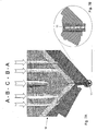
- films and moldings with a product sequence ABA or ABCBA can be formed.
- product sequences may be used for the manufacture of medical products, e.g. used in the manufacture of lingual and sublingual slides / tablets as well as transdermal patches. Such products can be very easily produced on the device according to the invention.
- the mouldable mass may be a bulk material.
- the device according to the invention can in particular compress polymer granules with high recovery force into shaped articles.
- the apparatus of the present invention can be used to process flowable and moldable powdered debris, e.g. in the pharmaceutical, food, cosmetics and hygiene industries.
- a moldable mass is formed and fed to a die grid so that it rests on the end faces of side boundaries of the die grid.
- a displacement bulkhead with side boundaries corresponding to the side boundaries of the die grid is then moved toward the die grid, causing the on-board boundaries displaced from the matrix grid resting part of the moldable mass in the direction of a receiving space formed by the matrix grid between the side boundaries, so that the moldable mass is portioned.
- At least one tool then compresses the portions of the moldable mass in the receiving space.
- the moldable material is supplied in particular continuously to the die grid.
- the displacement bulkhead is moved toward the die grid in such a way that the side boundaries of the displacement bulkhead are aligned with the side boundaries of the die grid.
- the displacement bulkhead is moved towards the die grid until the end faces of the side boundaries of the displacement bulkhead rest at least in part on the end faces of the side boundaries of the die grid.
- the displacement barrier can be moved in particular against the force of at least one spring on the die grid.
- a further die-side tool for the at least one receiving space is guided from the opposite side of the displacement-bulkhead-side tool into the receiving space.
- a multiplicity of receiving spaces can be formed in the die grid.
- pressure is exerted on the moldable material in each receiving space by a displacement-side-side tool and a die-side tool.
- the displacement-bulkhead-side tools and / or the die-side tools are in particular mounted in a respective tool carrier.
- at least one tool carrier is moved along a guideway, which has a shaping section in which a constant pressure is exerted by the tools on the portions of the mouldable mass located in the receiving spaces over a distance.
- the tool carrier is coupled in particular via a telescopic arm with a drive unit. It is moved by means of this drive unit, so that the tool carrier is guided on the guideway via a closed curve.
- a malleable mass is understood to mean any mass which changes its shape under the action of a force.
- a melt strand is formed as a moldable mass which is fed continuously to the matrix grid.
- the melt strand is preferably smoothed and aligned before it is fed to the die grid.
- pulverulent bulk materials can be supplied to the matrix grid as a moldable mass.
- multi-layer extrusion can be used to produce a molded article or a multilayer tablet which has a faster release of active substance from the outer layer and a delayed release of active substance of the inner layer, a multicomponent active ingredient release and realize a cascade-like drug release and by different thickness variations of the individual layers, different release profiles can be realized.
- multilayer moldings for the food, cosmetics and hygiene industries can thus be produced well.
- a per se known extruder 1 can be used.
- the design of the extruder 1 depends on the mass that is to be processed in the extruder 1.
- the masses to be processed may be e.g. be intended for use in the pharmaceutical industry, in the food industry as well as in the cosmetics and hygiene industries.
- a plastic melt is produced, which is ejected in the extruder die 10 as a melt strand 11.
- the melt strand 11 can be formed from only one melt.
- a multilayered melt strand 11 may also be formed, e.g. comprises two components A and B in three layers of sequence ABA.
- the extruder 1 may be configured to undergo three component extrusion in five plies of sequence ABCBA.
- the melt strand 11 ejected from the extruder die 10 is fed to a molding station 13 where counter rotating rolls 12A and 12B smooth the melt strand 11 into a melt ribbon 14. Furthermore, in the forming station 13, the width of the melt belt 14 can be set exactly. The width of the melt belt 14 depends on the width of the die grid 19, as will be explained later. The width is created by taperedêtsleitbleche. Corresponding side-prone preform prisms 12B take on the task of mass reduction on the sides of the melt belt.
- the Ausformstation thus the thickness and the width of the melt strip from which the moldings are formed, adjusted exactly. This setting ensures that the masses of the individual blanks are always the same. Furthermore, the height and thus the mass of the molded article to be formed can be adjusted via the thickness of the melt belt 14. In the forming station, a precompression of the moldable mass takes place, which leads to a higher stability of the melt belt 14. The thickness of the melt belt 14 depends on the consistency of the melt, their density and the desired individual weights of the moldings to be produced therefrom.
- the forming units 4 are guided on the guide track so that the upper part 4A of the forming unit 4 has approached the lower part 4B of the forming unit 4 behind the molding station 13 for the melt of the extruder 1.
- this forming section A (FIG. 2), they form a unit through which the shaped articles are formed from the melt strip 14.
- the forming unit 4 comprises a tool carrier 15 which is divided into an upper tool carrier 15A and a lower tool carrier 15B.
- the upper tool carrier 15A is fixed to an upper telescopic arm 5A
- the lower tool carrier 15B is fixed to a lower telescopic arm 5B.
- the telescopic arms 5A and 5B are arranged in a vertical plane parallel to each other. As already described with reference to FIGS. 1 and 2, they are moved horizontally, wherein they can perform vertical pivoting movements corresponding to the guide track 3.
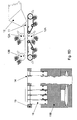
- the upper and lower tool carriers 15A and 15B are disposed adjacent to each other as shown in Fig. 9, as in the case of the forming section A, for example, the upper and lower tool carriers 15A and 15B are aligned with each other by guide rods 22. Lead by These guide rods 22 allow the upper and lower tool carriers 15A and 15B to move further toward each other.
- the upper and lower tool carriers 15A and 15B each include a plurality of guide pins 16A and 16B, respectively, which hold and guide the upper tool carrier 15A in two upper guide tracks 3A.
- the two upper guide tracks 3A are arranged at the same level at different radii with respect to the rotational movement of the drive unit 2.
- the lower guide bolts 16B hold and guide the lower tool carrier 15B in lower guide tracks 3B, respectively.
- three guide pins 16A and 16B are respectively provided for the upper and lower tool carriers 15A and 15B. They hold the two tool carrier parts 15A and 15B in a horizontal position, respectively.
- two guide pins 15A and 15B are respectively disposed on the outer guide track 3A and 3B, and the single guide pins 16A and 16B on the inner track 3A and 3B, respectively, for safe cornering of the tool carrier 15 receive.
- the upper and lower tool carriers 15A and 15B receive the same number of identical tools 17 and 18, respectively. Further, between the upper tool carrier 15A and the lower tool carrier 15B, a die grid 19 and a displacement barrier 38 are arranged, as will be explained later in detail. Both the die grid 19 and the displacement barrier 38 are guided by means of the guide rods 22.
Landscapes
- Engineering & Computer Science (AREA)
- Mechanical Engineering (AREA)
- Extrusion Moulding Of Plastics Or The Like (AREA)
Abstract
Description
Die vorliegende Erfindung betrifft eine Vorrichtung zum Bilden von Formlingen aus einer formbaren Masse. Die Vorrichtung umfasst ein Matrizengitter, in welchem zumindest ein von Seitenbegrenzungen gebildeter Aufnahmeraum ausgebildet ist, und zumindest ein Werkzeug, mit welchem die formbare Masse im Aufnahmeraum verpressbar ist. Ferner betrifft die Erfindung ein Verfahren zum Bilden von Formlingen, bei dem eine formbare Masse gebildet wird. Die formbare Masse wird einem Matrizengitter zugeführt und in einem Aufnahmeraum portioniert. Nach dem Portionieren verpresst zumindest ein Werkzeug die Portionen der formbaren Masse im Aufnahmeraum zu den Formlingen.The present invention relates to an apparatus for forming moldings from a moldable mass. The device comprises a die grid, in which at least one receiving space formed by side boundaries is formed, and at least one tool, with which the moldable mass in the receiving space can be pressed. Furthermore, the invention relates to a method for forming moldings, in which a moldable mass is formed. The moldable mass is fed to a die grid and portioned in a receiving space. After portioning, at least one tool presses the portions of the moldable mass in the receiving space to the moldings.
Aus der pharmazeutischen Industrie sind verschiedene Vorrichtungen und Verfahren zur Herstellung von Tabletten bekannt. Bei sog. Rundläufer-Tablettiermaschinen wird z.B. die zu formende Masse, welche als Schüttgut vorliegt, über eine feststehende Füllvorrichtung in einen ebenfalls feststehenden Matrizentisch zugeführt, in deren Aufnahmeräume (Matrizen) das Schüttgut eingefüllt wird. Oberhalb und unterhalb des Aufnahmeraums sind Stempel angeordnet, die zum Verpressen des Schüttguts über eine obere und eine untere Druckrolle geführt werden. Durch die Druckrollen werden die Stempel aufeinander zu bewegt, wodurch zunächst ein ansteigender und nach Überschreiten des Scheitelpunktes ein abfallender Druck auf das Schüttgut ausgeübt wird, wodurch es zu einer Tablette verpresst wird. Eine herkömmliche Rundläufer-Tablettiermaschine ist beispielsweise in der
Nachteilhaft an bekannten Tablettiermaschinen ist, dass das Zeitintervall, währenddessen der zum Verpressen erforderliche Druck auf die formbare Masse ausgeübt wird, begrenzt ist. Für viele Anwendungen ist es wünschenswert, die sog. Druckhaltezeit zu verlängern. Dies ist mit herkömmlichen Tablettiermaschinen nur mit einem geringen Zeitfenster möglich.A disadvantage of known tabletting machines is that the time interval during which the pressure required for pressing is exerted on the moldable mass is limited. For many applications, it is desirable to extend the so-called pressure hold time. This is possible with conventional tableting machines only with a small time window.
Aus der
Aus der
Des Weiteren ist es aus der
Das Kalandrierverfahren mit zwei Kalanderwalzen wird durch einen sog. Kettenkalander weitergebildet, wie er in der
Es ist die Aufgabe der vorliegenden Erfindung, eine Vorrichtung und ein Verfahren zum Bilden von Formlingen aus einer formbaren Masse anzugeben, bei denen die Formlinge schnell und effizient herstellbar sind. Es soll insbesondere der Anteil der zugeführten formbaren Masse, die nicht zu einem Formling geformt wird, so gering wie möglich sein.It is the object of the present invention to provide an apparatus and a method for forming moldings from a moldable mass, in which the moldings are produced quickly and efficiently. In particular, the proportion of supplied mouldable mass, which is not formed into a molding, should be as low as possible.
Diese Aufgabe wird durch eine Vorrichtung mit den Merkmalen des Anspruchs 1 und ein Verfahren mit den Merkmalen des Anspruchs 18 gelöst. Vorteilhafte Aus- und Weiterbildungen ergeben sich aus den Unteransprüchen.This object is achieved by a device having the features of
Die erfindungsgemäße Vorrichtung ist gekennzeichnet durch ein auf das Matrizengitter zu bewegbares Verdrängungsschott zum Portionieren der formbaren Masse, wobei das Verdrängungsschott Seitenbegrenzungen umfasst, die zu den Seitenbegrenzungen des Matrizengitters korrespondieren. Durch das Verdrängungsschott wird somit bei der erfindungsgemäßen Vorrichtung die formbare Masse vorportioniert, wobei zusätzlich die Materialüberstände auf dem Matrizengitter weitgehend vollständig in die Aufnahmeräume des Matrizengitters verdrängt werden und das Matrizengitter sodann einen vollständig umschlossenen Raum um die Einzelmassen bildet, welche sich anschließend mit entsprechend einstellbaren Volumina durch die im Matrizengitter nach unten drückenden Werkzeuge verpressen lassen. Auf diese Weise lassen sich Formlinge herstellen, die keine Randgrate und keinen Versatz aufweisen, so dass eine weitere Nachbearbeitung entfällt. Außerdem lassen sich glatte Oberflächenstrukturen und komplizierte Geometrien der Formlinge verwirklichen.The device according to the invention is characterized by a displacement bulkhead to be moved onto the matrix grid for portioning the moldable mass, wherein the displacement barrier comprises side boundaries which correspond to the lateral boundaries of the matrix grid. Thus, in the device according to the invention, the moldable mass is pre-portioned by the displacement bulkhead, wherein in addition the material overhangs on the matrix grid are largely completely displaced into the receiving spaces of the matrix grid and the matrix grid then forms a completely enclosed space around the individual masses, which subsequently has correspondingly adjustable volumes Press through the tools pressing down in the die grid. In this way it is possible to produce shaped articles which have no edge burrs and no offset have, so that a further post is omitted. In addition, smooth surface structures and complicated geometries of the moldings can be realized.
Bevorzugt fluchten die Seitenbegrenzungen des Verdrängungsschotts mit den Seitenbegrenzungen des Matrizengitters. Die Dicke der Seitenbegrenzungen des Matrizengitters entspricht insbesondere der Dicke der Seitenbegrenzungen des Verdrängungsschotts.Preferably, the side boundaries of the displacement bulkhead are aligned with the lateral boundaries of the matrix grid. The thickness of the side boundaries of the die grid corresponds in particular to the thickness of the side boundaries of the displacement partition.
Gemäß einer bevorzugten Ausgestaltung der erfindungsgemäßen Vorrichtung weisen die Seitenbegrenzungen des Verdrängungsschotts und die Seitenbegrenzungen des Matrizengitters Stirnflächen auf, die zumindest zum Teil zur Anlage kommen, wenn das Verdrängungsschott und das Matrizengitter vollständig aufeinander zu bewegt sind. Die jeweiligen Stirnflächen haben insbesondere dieselbe Geometrie. Beispielsweise kann das Matrizengitter ein quadratisches, rechteckiges, rautenförmiges oder kreisförmiges Raster umfassen. Dasselbe Raster wird dann von den Seitenbegrenzungen des Verdrängungsschotts gebildet, so dass die Stirnflächen jeweils aufeinander passen.According to a preferred embodiment of the device according to the invention, the side boundaries of the displacement bulkhead and the lateral boundaries of the matrix grid have end faces which at least partially come to rest when the displacement bulkhead and the matrix grid are moved towards each other completely. The respective end faces have in particular the same geometry. For example, the matrix grid may comprise a square, rectangular, diamond-shaped or circular grid. The same grid is then formed by the side boundaries of the displacement bulkhead, so that the end faces each match.
Gemäß einer Weiterbildung der erfindungsgemäßen Vorrichtung ist der Übergang von den Stirnflächen zu den Seitenbegrenzungen des Matrizengitters und/oder des Verdrängungsschotts abgerundet oder abgeschrägt. Hierdurch wird das Verdrängen der Massen beim Absenken der Verdrängungsschotts erleichtert und die Richtung des zu verdrängenden Materials in Richtung der Aufnahmeräume des Matrizengitters vorgegeben, wodurch sich der Ausschuss der zu formenden Massen nahezu vollständig reduziert.According to a development of the device according to the invention, the transition from the end faces to the side boundaries of the die grid and / or the displacement partition is rounded off or bevelled. As a result, the displacement of the masses during lowering of the displacement bulkhead is facilitated and predefined the direction of the material to be displaced in the direction of the receiving spaces of the matrix grid, whereby the reject of the masses to be formed almost completely reduced.
Gemäß einer Ausgestaltung der erfindungsgemäßen Vorrichtung ist das Werkzeug von den Seitenbegrenzungen des Verdrängungsschotts in den Aufnahmeraum führbar. Das Verdrängungsschott kann somit eine Doppelfunktion erfüllen. Zum einen dient es dem Portionieren der formbaren Masse. Zum anderen dient es als Führung für das Werkzeug.According to one embodiment of the device according to the invention, the tool can be guided from the side boundaries of the displacement bulkhead into the receiving space. The displacement bulkhead can thus fulfill a dual function. On the one hand, it serves to portion the moldable mass. On the other hand, it serves as a guide for the tool.
Gemäß einer Weiterbildung der erfindungsgemäßen Vorrichtung ist ein weiteres matrizenseitiges Werkzeug für den zumindest einen Aufnahmeraum von der gegenüberliegenden Seite des verdrängungsseitigen Werkzeugs in den Aufnahmeraum führbar. Auf diese Weise kann die formbare Masse in diesem Aufnahmeraum von zwei Seiten verpresst werden.According to a development of the device according to the invention, a further die-side tool for the at least one receiving space can be guided from the opposite side of the displacement-side tool into the receiving space. In this way, the moldable mass can be pressed in this receiving space from two sides.
In dem Matrizengitter ist insbesondere eine Vielzahl von Aufnahmeräumen gebildet, denen jeweils ein verdrängungsschottseitiges Werkzeug und ein matrizenseitiges Werkzeug zugeordnet sind. Dabei können die verdrängungsschottseitigen Werkzeuge und/oder die matrizenseitigen Werkzeuge in je einem Werkzeugträger gelagert sein. Sie sind insbesondere schwimmend in dem Werkzeugträger gesichert.In the die grid in particular a plurality of receiving spaces is formed, each associated with a displacement-side tool and a die-side tool. In this case, the displacement bulkhead-side tools and / or the die-side tools can be mounted in a respective tool carrier. They are particularly secured floating in the tool carrier.
Die Werkzeuge können insbesondere für bestimmte formbare Massen kühl- und/oder heizbar sein.The tools can be cooled and / or heated in particular for certain moldable masses.
Gemäß einer bevorzugten Weiterbildung der erfindungsgemäßen Vorrichtung ist das Verdrängungsschott mit dem Werkzeugträger für die verdrängungsschottseitigen Werkzeuge gekoppelt. Dabei ist das Verdrängungsschott insbesondere gegenüber dem Werkzeugträger gegen die Kraft zumindest einer Feder bewegbar.According to a preferred embodiment of the device according to the invention, the displacement bulkhead is coupled to the tool carrier for the displacement bulkhead-side tools. In this case, the displacement bulkhead is in particular movable relative to the tool carrier against the force of at least one spring.
Gemäß einer bevorzugten Weiterbildung der erfindungsgemäßen Vorrichtung ist zumindest ein Werkzeugträger entlang einer Führungsbahn bewegbar, die einen Formungsabschnitt aufweist, bei dem von den Werkzeugen ein konstanter Druck auf die in den Aufnahmeräumen befindlichen Portionen der formbaren Masse über eine Strecke ausgeübt wird. Der Formungsabschnitt der Führungsbahn verläuft insbesondere in einer geraden Strecke. Durch diese Ausgestaltung lässt sich die erfindungsgemäße Vorrichtung insbesondere zum Formen von Massen einsetzen, welche eine lange Druckhaltezeit benötigen. Der maximale Druck der Werkzeuge kann nämlich über die gesamte Strecke des Formungsabschnitts der Führungsbahn ausgeübt werden. Dieser Formungsabschnitt kann in Abhängigkeit von der Geschwindigkeit, mit welcher sich der Werkzeugträger auf der Führungsbahn bewegt, so lang gewählt werden, dass beliebige Druckhaltezeiten realisiert werden. Die Verweilzeit der Masse in dem Abschnitt, in welchem sie verpresst wird, ist somit einstellbar.According to a preferred development of the device according to the invention, at least one tool carrier is movable along a guideway having a forming section in which a constant pressure is exerted by the tools on the portions of the mouldable mass located in the receiving spaces over a distance. The shaping section of the guideway runs in particular in a straight line. As a result of this refinement, the device according to the invention can be used in particular for molding masses which require a long pressure holding time. Namely, the maximum pressure of the tools can be exerted over the entire distance of the forming section of the guideway. Depending on the speed with which the tool carrier moves on the guideway, this shaping section can be selected to be long enough to realize any desired pressure holding times. The residence time of the mass in the section in which it is compressed is thus adjustable.
Der Werkzeugträger wird insbesondere über eine Kulissenführung in der Führungsbahn gehalten. Des Weiteren kann für den Werkzeugträger der verdrängungsschottseitigen Werkzeuge und den Werkzeugträger der matrizenseitigen Werkzeuge je eine gesonderte Führungsbahn vorgesehen sein.The tool carrier is held in particular via a slotted guide in the guideway. Furthermore, a separate guideway may be provided for the tool carrier of the displacement bulkhead-side tools and the tool carrier for the die-side tools.
Gemäß einer Weiterbildung der erfindungsgemäßen Vorrichtung läuft zumindest ein Werkzeugträger entlang der Führungsbahn zumindest abschnittsweise auf Führungsrollen, wobei zumindest im Formungsabschnitt der Führungsbahn die Führungsrollen hinsichtlich ihres Abstands zum Werkzeugträger der verdrängungsschottseitigen Werkzeuge hin justierbar. Hierdurch kann ein Formungsdruck entsprechend der zu formenden Masseneigenschaften eingestellt werden. Die einzustellenden Volumina der unterschiedlichen zu verpressenden Massen werden mittels des höhenverstellbaren Matrizengitters eingestellt. Bei dem erfindungsgemäßen Verfahren lässt sich somit ein Online-Wechsel der Darreichungsformen hinsichtlich der Dosierung realisieren. Des Weiteren lassen sich Toleranzen der Führungsbahn im Formungsabschnitt ausgleichen.According to a development of the device according to the invention, at least one tool carrier along the guideway at least partially runs on guide rollers, wherein at least in the forming section of the guideway, the guide rollers with respect to their distance to the tool carrier of displacement-side tools adjustable. As a result, a molding pressure can be set according to the mass properties to be molded. The volumes to be set of the different masses to be pressed are adjusted by means of the height-adjustable die grid. In the method according to the invention, it is thus possible to realize an online change of the administration forms with regard to the metering. Furthermore, tolerances of the guideway in the forming section can be compensated.
In Verarbeitungsrichtung hinter dem Formungsabschnitt kann bei der erfindungsgemäßen Vorrichtung ein Auskühlabschnitt von der Führungsbahn gebildet sein, bei dem die verpressten Formlinge in dem Matrizengitter auskühlen. Insbesondere bei pharmazeutischen Formlingen ist es häufig erforderlich, dass lange Auskühlzeiten realisiert werden, um etwaigen Restspannungen in den Formlingen entgegenzuwirken.In the processing direction behind the molding section can be formed in the device according to the invention, a cooling section of the guideway, in which cool the pressed moldings in the die grid. In particular, in pharmaceutical moldings, it is often necessary that long Auskühlzeiten be realized to counteract any residual stresses in the moldings.
Nach dem Formungsabschnitt bzw. nach dem Auskühlabschnitt kann eine Probenentnahmestation zur Entnahme von einem oder mehreren Formlingen angeordnet sein, welche einer Qualitätskontrolle zugeführt werden können. Daran anschließend kann eine Entnahme- und Kamerainspektionsstation zur Entnahme und Untersuchung der Formlinge, eine Reinigungsstation für zumindest die Werkzeuge, das Verdrängungsschott und das Matrizengitter und schließlich eine Formungsraumbeschichtungseinrichtung angeordnet sein, bei welcher die Teile der Vorrichtung, die mit der formbaren Masse in Berührung kommen, zur Vermeidung von Anhaftungen beschichtet werden.After the shaping section or after the cooling section, a sampling station for removing one or more moldings can be arranged, which can be fed to a quality control. Thereafter, a removal and camera inspection station for removal and examination of the moldings, a cleaning station for at least the tools, the displacement barrier and the matrix grid and finally a Formungsraumbeschichtungseinrichtung be arranged, in which the parts of the device, which come into contact with the moldable mass, be coated to avoid buildup.
Die Werkzeugreinigung sowie die Formungsraumbeschichtung lassen sich somit während des laufenden Herstellungsprozesses kontinuierlich durchführen. Außerdem sind eine Online-Kontrolle während des laufenden Herstellungsprozesses sowie eine Online-Massenkorrektur der Formlinge möglich. Des Weiteren sind eine Online-100% Sichtkontrolle mittels einer Kamera sowie Online-NIR für diverse analytische Datenerhebungen möglich.The tool cleaning and the molding space coating can thus be carried out continuously during the ongoing production process. In addition, an online control during the ongoing manufacturing process and an online mass correction of the moldings are possible. Furthermore, an online 100% visual inspection by means of a camera as well as online NIR for various analytical data collections are possible.
Aufgrund der Formungsraumbeschichtung und der einstellbaren Auskühlzeit lassen sich bei der Durchführung thermischer Verfahren auch Formlinge mit komplizierten Geometrien gut entformen.Due to the molding space coating and the adjustable cooling time, moldings with complicated geometries can also be demoulded well when carrying out thermal processes.
Gemäß einer bevorzugten Ausbildung der erfindungsgemäßen Vorrichtung ist der Werkzeugträger über einen Teleskoparm mit einer drehbaren Antriebseinheit gekoppelt, so dass der Werkzeugträger über eine geschlossene Kurve führbar ist. Die Antriebseinheit kann die einzige angetriebene Einheit der erfindungsgemäßen Vorrichtung sein. Bevorzugt ist für den Werkzeugträger der verdrängungsseitigen Werkzeuge und den Werkzeugträger der matrizenseitigen Werkzeuge je ein Teleskoparm vorgesehen. Der Teleskoparm bzw. die Teleskoparme können insbesondere um eine hinsichtlich der Drehung der Antriebseinheit tangentiale Achse schwenkbar gelagert sein. Ferner ist die Länge des Teleskoparms veränderbar. Der Werkzeugträger ist in diesem Fall über einen Horizontal-/Vertikalgabelgelenk mit dem Teleskoparm gekoppelt. Auf diese Weise kann sich der Werkzeugträger entlang der Führungsbahn zum einen radial auf die Antriebseinheit zu- bzw. von der Antriebseinheit wegbewegen. Zum anderen kann der Werkzeugträger bei einer horizontalen Drehebene nach oben und nach unten verschwenkt werden.According to a preferred embodiment of the device according to the invention, the tool carrier is coupled via a telescopic arm with a rotatable drive unit, so that the tool carrier can be guided over a closed curve. The drive unit may be the only driven unit of the device according to the invention. Preferably, a telescopic arm is provided for the tool carrier of the displacement-side tools and the tool carrier of the die-side tools. The telescopic arm or the telescopic arms can in particular be mounted so as to be pivotable about an axis tangential with respect to the rotation of the drive unit. Furthermore, the length of the telescopic arm is variable. The tool carrier is coupled in this case via a horizontal / vertical fork joint with the telescopic arm. In this way, the tool carrier can move radially along the guide track to the drive unit or away from the drive unit. On the other hand, the tool carrier can be pivoted upwards and downwards in a horizontal plane of rotation.
Bei der formbaren Masse kann es sich insbesondere um ein Schmelzeband handeln. Zum Bilden des Schmelzebands umfasst die Vorrichtung insbesondere einen Extruder, wobei das Schmelzeband dem Matrizengitter kontinuierlich zuführbar ist. Vorzugsweise ist zwischen dem Extruder und dem Matrizengitter eine Ausformungseinrichtung zum Glätten und Ausrichten eines vom Extruder ausgestoßenen Schmelzestrangs zu dem Schmelzeband angeordnet. Auf diese Weise kann die Breite des Schmelzebands so geformt werden, dass sie der Breite des Matrizengitters entspricht. Die Dicke des Schmelzebandes kann hierdurch so eingestellt werden, dass das Gewicht der einzelnen Portionen der Masse eingestellt wird.The mouldable mass may in particular be a melt ribbon. For forming the melt ribbon, the device comprises in particular an extruder, wherein the melt ribbon is continuously fed to the die grid. Preferably, a shaping device for smoothing and aligning a melt strand ejected from the extruder to the melt ribbon is arranged between the extruder and the die grid. In this way, the width of the melt ribbon can be shaped to match the width of the die grid equivalent. The thickness of the melt ribbon can thereby be adjusted so that the weight of the individual portions of the mass is adjusted.
Das Schmelzeband kann, falls erforderlich, mehrere Schichten unterschiedlicher Zusammensetzung umfassen. Der Extruder kann insbesondere zur Zwei- oder Dreikomponentenextrusion ausgebildet sein, wobei die verschiedenen Komponenten in verschiedenen Folgen aneinander liegen können. Beispielsweise lassen sich Filme und Formlinge mit einer Produktfolge ABA oder ABCBA bilden. Derartige Produktfolgen können für die Herstellung von medizinalen Produkten, z.B. bei der Herstellung von Lingual- sowie Sublingualfolien/-Tabletten sowie bei transdermalen Pflastern eingesetzt werden. Derartige Produkte lassen sich auf der erfindungsgemäßen Vorrichtung sehr einfach herstellen.If necessary, the melt ribbon may comprise several layers of different composition. The extruder can be designed in particular for two- or three-component extrusion, wherein the various components can be in different sequences to each other. For example, films and moldings with a product sequence ABA or ABCBA can be formed. Such product sequences may be used for the manufacture of medical products, e.g. used in the manufacture of lingual and sublingual slides / tablets as well as transdermal patches. Such products can be very easily produced on the device according to the invention.
Gleichermaßen sind auch Anwendungen aus der Lebensmittelindustrie mittels Coextrusion realisierbar. Hierbei können weichere Elemente von Formlingen, z.B. Bonbons, mit Schichten, die eine zähere Konsistenz aufweisen, in verschiedenen Produktfolgen überlagert werden, um auf diese Weise bislang schlecht verarbeitbare Lebensmittel besser behandeln sowie konfektionieren zu können. Des Weiteren können mehrere Lagen aus unterschiedlichsten Aromenschmelzen zu einem Bonbon hergestellt werden.Likewise, applications from the food industry can be realized by means of coextrusion. Here, softer elements of moldings, e.g. Candies, with layers that have a tougher consistency, are superimposed in different product sequences in order to be able to better treat and assemble foods that have previously been difficult to process. Furthermore, several layers of different aromas can be made into a candy.
Des Weiteren kann es sich bei der formbaren Masse um ein Schüttgut handeln. Die erfindungsgemäße Vorrichtung kann insbesondere Polymergranulate mit hoher Rückstellkraft zu Formlingen verpressen. Bevorzugt lässt sich die erfindungsgemäße Vorrichtung wegen der einstellbaren Formungszeit für den Formungsvorgang zur Verarbeitung fließfähiger und formbarer pulverförmiger Schuttgüter, z.B. in der pharmazeutischen, der Lebensmittel-, der Kosmetik- sowie der Hygieneindustrie einsetzen.Furthermore, the mouldable mass may be a bulk material. The device according to the invention can in particular compress polymer granules with high recovery force into shaped articles. Preferably, because of the adjustable molding time for the molding process, the apparatus of the present invention can be used to process flowable and moldable powdered debris, e.g. in the pharmaceutical, food, cosmetics and hygiene industries.
Bei dem erfindungsgemäßen Verfahren zum Bilden von Formlingen wird eine formbare Masse gebildet und einem Matrizengitter zugeführt, so dass sie auf den Stirnseiten von Seitenbegrenzungen des Matrizengitters aufliegt. Ein Verdrängungsschott mit Seitenbegrenzungen, die zu den Seitenbegrenzungen des Matrizengitters korrespondieren, wird dann auf das Matrizengitter zu bewegt, wodurch der auf den Seitenbegrenzungen des Matrizengitters aufliegende Teil der formbaren Masse in Richtung eines von dem Matrizengitter zwischen den Seitenbegrenzungen gebildeten Aufnahmeraums verdrängt wird, so dass die formbare Masse portioniert wird. Zumindest ein Werkzeug verpresst danach die Portionen der formbaren Masse im Aufnahmeraum.In the method according to the invention for forming moldings, a moldable mass is formed and fed to a die grid so that it rests on the end faces of side boundaries of the die grid. A displacement bulkhead with side boundaries corresponding to the side boundaries of the die grid is then moved toward the die grid, causing the on-board boundaries displaced from the matrix grid resting part of the moldable mass in the direction of a receiving space formed by the matrix grid between the side boundaries, so that the moldable mass is portioned. At least one tool then compresses the portions of the moldable mass in the receiving space.
Die formbare Masse wird insbesondere dem Matrizengitter kontinuierlich zugeführt. Das Verdrängungsschott wird insbesondere so auf das Matrizengitter zu bewegt, dass die Seitenbegrenzungen des Verdrängungsschotts mit den Seitenbegrenzungen des Matrizengitters fluchten. Dabei wird das Verdrängungsschott auf das Matrizengitter zu bewegt, bis die Stirnseiten der Seitenbegrenzungen des Verdrängungsschotts zumindest zum Teil an den Stirnseiten der Seitenbegrenzungen des Matrizengitters anliegen. Das Verdrängungsschott kann insbesondere gegen die Kraft zumindest einer Feder auf das Matrizengitter zu bewegt werden.The moldable material is supplied in particular continuously to the die grid. In particular, the displacement bulkhead is moved toward the die grid in such a way that the side boundaries of the displacement bulkhead are aligned with the side boundaries of the die grid. In this case, the displacement bulkhead is moved towards the die grid until the end faces of the side boundaries of the displacement bulkhead rest at least in part on the end faces of the side boundaries of the die grid. The displacement barrier can be moved in particular against the force of at least one spring on the die grid.
Beim Verpressen wird bei einer Ausgestaltung des erfindungsgemäßen Verfahrens das Werkzeug von den Seitenbegrenzungen des Verdrängungsschotts in den Aufnahmeraum geführt. Des Weiteren wird vorzugsweise beim Verpressen ein weiteres matrizenseitiges Werkzeug für den zumindest einen Aufnahmeraum von der gegenüberliegenden Seite des verdrängungsschottseitigen Werkzeugs in den Aufnahmeraum geführt.When pressing the tool is guided by the side boundaries of the displacement in the receiving space in an embodiment of the method according to the invention. Furthermore, preferably during pressing, a further die-side tool for the at least one receiving space is guided from the opposite side of the displacement-bulkhead-side tool into the receiving space.
In dem Matrizengitter kann insbesondere eine Vielzahl von Aufnahmeräumen gebildet sein. Beim Verpressen wird auf die formbare Masse in jedem Aufnahmeraum ein Druck von einem verdrängungsschottseitigen Werkzeug und einem matrizenseitigen Werkzeug ausgeübt.In particular, a multiplicity of receiving spaces can be formed in the die grid. During pressing, pressure is exerted on the moldable material in each receiving space by a displacement-side-side tool and a die-side tool.
Die verdrängungsschottseitigen Werkzeuge und/oder die matrizenseitigen Werkzeuge sind insbesondere in je einem Werkzeugträger gelagert. Gemäß einer bevorzugten Weiterbildung des erfindungsgemäßen Verfahrens wird zumindest ein Werkzeugträger entlang einer Führungsbahn bewegt, die einen Formungsabschnitt aufweist, bei dem von den Werkzeugen ein konstanter Druck auf die in den Aufnahmeräumen befindlichen Portionen der formbaren Masse über eine Strecke ausgeübt wird.The displacement-bulkhead-side tools and / or the die-side tools are in particular mounted in a respective tool carrier. According to a preferred development of the method according to the invention, at least one tool carrier is moved along a guideway, which has a shaping section in which a constant pressure is exerted by the tools on the portions of the mouldable mass located in the receiving spaces over a distance.
Der Werkzeugträger ist insbesondere über einen Teleskoparm mit einer Antriebseinheit gekoppelt. Er wird mittels dieser Antriebseinheit bewegt, so dass der Werkzeugträger auf der Führungsbahn über eine geschlossene Kurve geführt wird.The tool carrier is coupled in particular via a telescopic arm with a drive unit. It is moved by means of this drive unit, so that the tool carrier is guided on the guideway via a closed curve.
Unter einer formbaren Masse im Sinne der Erfindung wird jede Masse verstanden, die unter Einwirkung einer Kraft ihre Gestalt verändert. Als formbare Masse wird insbesondere ein Schmelzestrang gebildet, der dem Matrizengitter kontinuierlich zugeführt wird. Der Schmelzestrang wird, bevor er dem Matrizengitter zugeführt wird, bevorzugt geglättet und ausgerichtet. Ferner können als formbare Masse pulverförmige Schüttgüter dem Matrizengitter zugeführt werden.For the purposes of the invention, a malleable mass is understood to mean any mass which changes its shape under the action of a force. In particular, a melt strand is formed as a moldable mass which is fed continuously to the matrix grid. The melt strand is preferably smoothed and aligned before it is fed to the die grid. Furthermore, pulverulent bulk materials can be supplied to the matrix grid as a moldable mass.
Bei der Anwendung der erfindungsgemäßen Vorrichtung bzw. des erfindungsgemäßen Verfahrens in der pharmazeutischen Industrie zur Herstellung von wirkstoffhaltigen Formlingen lassen sich z.B. folgende Anwendungsmerkmale realisieren: durch eine sog. Schutzextrusion lassen sich sensible Wirkstoffe abschirmen, durch eine Mehrlagenextrusion lässt sich ein Formling bzw. eine Mehrlagentablette realisieren, der eine schnellere Wirkstofffreisetzung der äußeren Schicht und eine verzögerte Wirkstofffreisetzung der inneren Schicht aufweist, es lässt sich eine Mehrkomponentenwirkstoffabgabe und eine kaskadenartige Wirkstofffreigabe realisieren und durch unterschiedliche Dickenvariationen der einzelnen Schichten lassen sich verschiedene Freisetzungsprofile realisieren. Insbesondere Mehrlagenformlinge für die Lebensmittel-, Kosmetik- sowie Hygieneindustrien lassen sich damit gut herstellen.When using the device according to the invention or the method according to the invention in the pharmaceutical industry for the production of active substance-containing moldings, e.g. By means of a so-called protective extrusion, sensitive active substances can be shielded; multi-layer extrusion can be used to produce a molded article or a multilayer tablet which has a faster release of active substance from the outer layer and a delayed release of active substance of the inner layer, a multicomponent active ingredient release and realize a cascade-like drug release and by different thickness variations of the individual layers, different release profiles can be realized. In particular, multilayer moldings for the food, cosmetics and hygiene industries can thus be produced well.
Die Erfindung wird nun anhand von Ausführungsbeispielen mit Bezug zu den Zeichnungen im Detail erläutert:
- Fig. 1
- zeigt schematisch den Gesamtaufbau der Vorrichtung gemäß einem Ausführungsbeispiel der Erfindung,
- Fig. 2
- zeigt einen Ausschnitt der in Fig. 1 gezeigten Vorrichtung, in welchem die verschiedenen Stationen der Vorrichtung erkennbar sind,
- Fig. 3
- zeigt die beidseitig höhenveränderbare Fahrkurve des oberen und unteren Teils der Formungseinheit beim Kurvenfahren nach dem Formungsprozess,
- Fig. 4
- zeigt die beidseitig höhenveränderbare Fahrkurve des oberen und unteren Teils der Formungseinheit beim Kurvenfahren zum Formungsprozess,
- Fig. 5
- zeigt eine Seitenansicht der in den Fig. 3 und 4 gezeigten Fahrkurven der Vorrichtung gemäß dem Ausführungsbeispiel der Erfindung,
- Fig. 6A
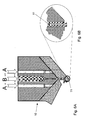
- zeigt die Düse eines Extruders der Vorrichtung gemäß dem Ausführungsbeispiels der Erfindung, insbesondere für die Herstellung von Mehrlagenformlingen/Mehrlagentabletten,
- Fig. 6B
- zeigt eine Detailansicht der Fig. 6A,
- Fig. 7A
- zeigt eine andere Ausgestaltung der Düse des Extruders der Vorrichtung gemäß einem Ausführungsbeispiel der Erfindung, insbesondere für die Herstellung von Mehrlagenformlingen/Mehrlagentabletten,
- Fig. 7B
- zeigt eine Detailansicht der Fig. 7A,
- Fig. 8A bis 8D
- zeigen das Zusammenführen des oberen und unteren Teils der Formungseinheit beim Extruder bei der Vorrichtung gemäß dem Ausführungsbeispiel der Erfindung,
- Fig. 9
- zeigt die Formungseinheit der Vorrichtung gemäß dem Ausführungsbeispiel der Erfindung im Detail,
- Fig. 10
- zeigt den Teleskoparm der Vorrichtung gemäß dem Ausführungsbeispiel der Erfindung,
- Fig. 11
- zeigt den Fahr- und Bewegungsweg des Werkzeugträgerunterteils im Bereich des Formungsabschnitts der Vorrichtung gemäß dem Ausführungsbeispiel der Erfindung,
- Fig. 12
- zeigt eine Detailansicht des Führungsbolzens im Bereich des Formungsabschnitts der Vorrichtung gemäß dem Ausführungsbeispiel der Erfindung,
- Fig. 13
- zeigt ein Detail des Führungsbolzens in der Kulissenführung,
- Fig. 14A
- zeigt eine Aufsicht auf ein Beispiel eines Werkzeugs,
- Fig. 14B
- und 14C zeigen perspektivische Ansichten eines Beispiels eines Werkzeugs,
- Fig. 15A
- zeigt eine Aufsicht auf ein anderes Werkzeug,
- Fig. 15B
- zeigt eine perspektivische Ansicht dieses anderen Werkzeugs,
- Fig. 16A
- zeigt eine Aufsicht auf ein weiteres Werkzeug,
- Fig. 16B
- zeigt eine perspektivische Ansicht des weiteren Werkzeugs,
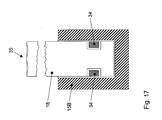
- Fig. 17
- zeigt eine Schnittansicht des Werkzeugs in dem Werkzeugträger der Vorrichtung gemäß dem Ausführungsbeispiel der Erfindung,
- Fig. 18
- zeigt ein Spezialwerkzeug der Vorrichtung gemäß dem Ausführungsbeispiel der Erfindung,
- Fig. 19
- zeigt ein Detail des in Fig. 18 gezeigten Spezialwerkzeugs,
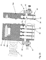
- Fig. 20
- zeigt eine Schnittansicht des oberen Werkzeugträgers und den damit verbundenen Teilen der Vorrichtung gemäß dem Ausführungsbeispiel der Erfindung,
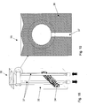
- Fig. 21
- zeigt das Verdrängungsschott der Vorrichtung gemäß dem Ausführungsbeispiel der Erfindung,
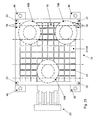
- Fig. 22
- zeigt den unteren Werkzeugträger und die mit diesem verbundenen Teile der Vorrichtung gemäß dem Ausführungsbeispiel der Erfindung,
- Fig. 23
- zeigt das Matrizengitter der Vorrichtung gemäß dem Ausführungsbeispiel der Erfindung,
- Fig. 24A
- zeigt das Zusammenspiel des oberen und unteren Werkzeugträgers bei der Verarbeitung von Schmelzen,
- Fig. 24B
- zeigt das Zusammenspiel des oberen und des unteren Werkzeugträgers bei der Verarbeitung von Schüttgütern,
- Fig. 25A und 25B
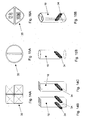
- veranschaulichen die Wirkung eines ersten Beispiels des Verdrängungsschotts der Vorrichtung gemäß dem Ausführungsbeispiel der Erfindung,
- Fig. 26A und 26B
- veranschaulichen die Wirkung eines zweiten Beispiels des Verdrängungsschotts der Vorrichtung gemäß dem Ausführungsbeispiel der Erfindung,
- Fig. 27A
- und 27B veranschaulichen die Kräfteverteilung in dem Aufnahmeraum des Matrizengitters der Vorrichtung gemäß dem Ausführungsbeispiel der Erfindung,
- Fig. 28
- zeigt die Formlingsentnahme- und Kamerainspektionsstation der Vorrichtung gemäß dem Ausführungsbeispiel der Erfindung,
- Fig. 29
- zeigt die Reinigungsstation der Vorrichtung gemäß dem Ausführungsbeispiel der Erfindung,
- Fig. 30
- zeigt einen weiteren Teil der Reinigungsstation der Vorrichtung gemäß dem Ausführungsbeispiel der Erfindung und
- Fig. 31
- zeigt die Formungsraumbeschichtungseinheit der Vorrichtung gemäß dem Ausführungsbeispiel der Erfindung.
- Fig. 1
- shows schematically the overall structure of the device according to an embodiment of the invention,
- Fig. 2
- shows a section of the device shown in Figure 1, in which the various stations of the device are recognizable,
- Fig. 3
- shows the two-way height-adjustable travel curve of the upper and lower part of the molding unit when cornering after the molding process,
- Fig. 4
- shows the double-sided height-adjustable travel curve of the upper and lower part of the molding unit when cornering for forming process,
- Fig. 5
- shows a side view of the driving curves of the device according to the embodiment of the invention shown in FIGS. 3 and 4,
- Fig. 6A
- shows the nozzle of an extruder of the device according to the embodiment of the invention, in particular for the production of multilayer preforms / multilayer tablets,
- Fig. 6B
- shows a detailed view of FIG. 6A,
- Fig. 7A
- shows another embodiment of the nozzle of the extruder of the device according to an embodiment of the invention, in particular for the production of multilayer tablets / multilayer tablets,
- Fig. 7B
- shows a detailed view of Fig. 7A,
- 8A to 8D
- show the merging of the upper and lower parts of the molding unit in the extruder in the apparatus according to the embodiment of the invention,
- Fig. 9
- shows the molding unit of the device according to the embodiment of the invention in detail,
- Fig. 10
- shows the telescopic arm of the device according to the embodiment of the invention,
- Fig. 11
- shows the travel and movement path of the tool carrier lower part in the region of the forming section of the device according to the exemplary embodiment of the invention,
- Fig. 12
- shows a detailed view of the guide pin in the region of the forming portion of the device according to the embodiment of the invention,
- Fig. 13
- shows a detail of the guide pin in the slotted guide,
- Fig. 14A
- shows a plan view of an example of a tool,
- Fig. 14B
- and FIG. 14C show perspective views of an example of a tool,
- Fig. 15A
- shows a view of another tool,
- Fig. 15B
- shows a perspective view of this other tool,
- Fig. 16A
- shows a view of another tool,
- Fig. 16B
- shows a perspective view of the further tool,
- Fig. 17
- shows a sectional view of the tool in the tool carrier of the device according to the embodiment of the invention,
- Fig. 18
- shows a special tool of the device according to the embodiment of the invention,
- Fig. 19
- shows a detail of the special tool shown in Fig. 18,
- Fig. 20
- shows a sectional view of the upper tool carrier and the associated parts of the device according to the embodiment of the invention,
- Fig. 21
- shows the displacement barrier of the device according to the embodiment of the invention,
- Fig. 22
- shows the lower tool carrier and the associated therewith parts of the device according to the embodiment of the invention,
- Fig. 23
- shows the die grid of the device according to the embodiment of the invention,
- Fig. 24A
- shows the interaction of the upper and lower tool carrier in the processing of melts,
- Fig. 24B
- shows the interaction of the upper and the lower tool carrier in the processing of bulk materials,
- Figs. 25A and 25B
- illustrate the effect of a first example of the displacement bulkhead of the device according to the embodiment of the invention,
- Figs. 26A and 26B
- illustrate the effect of a second example of the displacement bulkhead of the device according to the embodiment of the invention,
- Fig. 27A
- and Fig. 27B illustrate the distribution of forces in the receiving space of the die grid of the device according to the embodiment of the invention,
- Fig. 28
- shows the blank removal and camera inspection station of the device according to the embodiment of the invention,
- Fig. 29
- shows the cleaning station of the device according to the embodiment of the invention,
- Fig. 30
- shows a further part of the cleaning station of the device according to the embodiment of the invention and
- Fig. 31
- shows the molding space coating unit of the device according to the embodiment of the invention.
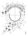
Mit Bezug zu den Fig. 1 und 2 wird ein Überblick über den Gesamtaufbau der Vorrichtung zum Bilden von Formlingen aus der formbaren Masse gegeben:
- Die Vorrichtung umfasst einen Extruder 1, mit dem eine formbare Masse gebildet werden kann. Von der Düse des
Extruders 1 wird die formbare Masse in ein rotierendes mechanisches System überführt, in dem die Formlinge gebildet werden. Der grundsätzliche Aufbau dieses rotierenden mechanischen Systems wird im Folgenden erläutert. - Es ist eine drehbare Antriebseinheit 2 vorgesehen, an welcher radial nach außen erstreckende Teleskoparme 5 befestigt sind. An den radial außen liegenden Enden der
Teleskoparme 5sind Formungseinheiten 4 befestigt. Wie es später erläutert wird, setzt sich eine Formungseinheit aus einem oberen Teil 4A und einem unteren Teil 4B zusammen. Sowohl fürden oberen Teil 4A als auch fürden unteren Teil 4Bist ein Teleskoparm 5A bzw. 5B vorgesehen.Der Teleskoparm 5A fürden oberen Teil 4A und derjenige 5B fürden unteren Teil 4B der Formungseinheit 4 sind parallel vertikal übereinander liegend angeordnet.Die Antriebseinheit 2 umfasst somit in einer oberen horizontalenEbene die Teleskoparme 5A fürden oberen Teil 4A der Formungseinheit 4 und in einer unteren horizontalenEbene die Teleskoparme 5B fürden unteren Teil 4B derFormungseinheit 4.Die Teleskoparme 5mit den Formungseinheiten 4 werden somitvon der Antriebseinheit 2 im Wesentlichen in einer oberen und einer unteren horizontalen Ebene bewegt. Die Formungseinheiten 4 werden auf einer Führungsbahn 3 geführt.Die Führungsbahn 3 beschreibt eine geschlossene Kurve mit geraden Abschnitten A und B (Fig. 2) und einem halbkreisförmigen Abschnitt der gegenüberliegend zu den Abschnitten A und B angeordnet ist.Damit die Formungseinheiten 4 durch eine Drehung der Antriebseinheit 2 auf dieser Führungsbahn 3 geführt werden können, ist die radiale Länge der Teleskoparme 5 veränderbar. Außerdem kann dieFührungsbahn 3 auch in vertikaler Richtung dieLage der Formungseinheiten 4 verändern. Hierfür können dieTeleskoparme 5 eine vertikale Schwenkbewegung ausführen, d. h. eine Schwenkbewegung um Achse, die parallel zu einer hinsichtlich der Drehbewegung der Antriebseinheit 2 tangentialen Achse ist. Zur Begrenzung der vertikalen Schwenkbewegung sind bei denAchsbefestigungen der Teleskoparme 5 ander Antriebseinheit 2 seitliche Führungen vorgesehen.Die Teleskoparme 5 lassen sich somit von der Antriebseinheit 2 horizontal bewegen, wobei sie bei dieser Bewegung vertikale Schwenkbewegungen ausführen können, wobei die Wegevon der Führungsbahn 3 vorgegeben sind.- Mit Bezug zu Fig. 2 werden die verschiedenen Abschnitte, welche die Führungsbahn durchläuft, beschrieben:
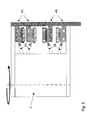
- Direkt an die Düse des
Extruders 1 schließt sich ein Formungsabschnitt A an, bei welchem dieFührungsbahn 3 auf einer geraden Strecke verläuft. An den Formungsabschnitt A schließt sich ein Auskühlabschnitt B an, welcher auch auf einer geraden Strecke verlaufen kann. Hinter dem Auskühlabschnitt Bändert die Führungsbahn 3 in einem 90°-Bogen ihre Richtung und führt dieFormungseinheiten 4 bei dem Abschnitt C einerProbenentnahmestation 6 zu. Nach dem Abschnitt C beschreibt dieFührungsbahn 3 einen Halbkreis, aufdem die Formungseinheiten 4 bei einem Abschnitt D einer Formlingsentnahme-und Kamerainspektionsstation 7, beim AbschnittE einer Reinigungsstation 8 und beim AbschnittF einer Formungsraumbeschichtungseinrichtung 9 zugeführt wird. Die einzelnen Stationen und Einrichtungen dieser Abschnitte werden später im Detail beschrieben. - Nachdem die
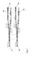
Formungseinheiten 4die Formungsraumbeschichtungseinrichtung 9 verlassen haben, werden sie über einen 90°-Bogen zurück zu dem Formungsabschnitt A geführt. Da die dicht aneinander angeordneten Formungseinheiten 4 in dieser Konstellation nicht über ihre Diagonale hinweg eine Kurvenbewegung durchführen können, sind für die Führungsbahn Ausweichfahrkurven gebildet, die im Folgenden mit Bezug zu den Fig. 3bis 5 erläutert werden:- Die Fig. 3 zeigt eine obere
Führungsbahn 3A fürden oberen Teil 4A der Formungseinheit 4 und eine untere Führungsbahn 3B fürden unteren Teil 4B derFormungseinheit 4. In Fig. 3 ist das Auseinanderfahren der oberen und unteren Teile 4A bzw. 4B der Formungseinheit 4 gezeigt. Fig. 4 zeigt das Zusammenfahren der jeweiligen Teile der Formungseinheit 4.Die obere Führungsbahn 3A unddie untere Führungsbahn 3B teilen sich jeweils erneut in einen oberen und unteren Teil, auf denen jeweils abwechselnd die beiden Teile der Formungseinheit 4 zugeführt werden. Die Steuerung erfolgt über Weichen, welche die Umleitung in die jeweilige Fahrkurve bewirkt. In Fig. 5 ist eine Seitenansicht gezeigt, welche die Bewegung des oberenTeleskoparms 5A fürden oberen Teil 4A der Formungseinheit 4 und des unteren Teleskoparms 5B fürden unteren Teil 4B der Formungseinheit 4 zeigt.
- Die Fig. 3 zeigt eine obere
- Direkt an die Düse des
- The device comprises an
extruder 1, with which a moldable mass can be formed. From the nozzle of theextruder 1, the moldable mass is transferred to a rotating mechanical system in which the moldings are formed. The basic structure of this rotating mechanical system will be explained below. - There is a
rotatable drive unit 2 is provided, are attached to which radially outwardly extendingtelescopic arms 5. At the radially outer ends of thetelescopic arms 5 formingunits 4 are attached. As will be explained later, a molding unit is composed of anupper part 4A and alower part 4B. Both for theupper part 4A and for thelower part 4B atelescopic arm telescopic arm 5A for theupper part 4A and that 5B for thelower part 4B of the formingunit 4 are arranged vertically one above the other vertically. Thedrive unit 2 thus comprises in an upper horizontal plane thetelescopic arms 5A for theupper part 4A of the formingunit 4 and in a lower horizontal plane thetelescopic arms 5B for thelower part 4B of the formingunit 4. Thetelescopic arms 5 with the formingunits 4 are thus of theDrive unit 2 is moved substantially in an upper and a lower horizontal plane. - The shaping
units 4 are guided on aguideway 3. Theguide track 3 describes a closed curve with straight sections A and B (FIG. 2) and a semicircular section which is arranged opposite to the sections A and B. So that the shapingunits 4 can be guided by a rotation of thedrive unit 2 on thisguideway 3, the radial length of thetelescopic arms 5 is variable. In addition, theguide track 3 can also change the position of the shapingunits 4 in the vertical direction. For this purpose, thetelescopic arms 5 perform a vertical pivoting movement, ie a Pivoting movement about axis which is parallel to a tangential with respect to the rotational movement of thedrive unit 2 axis. To limit the vertical pivoting movement, lateral guides are provided on thedrive unit 2 in the axle fastenings of thetelescopic arms 5. Thetelescopic arms 5 can thus be moved horizontally by thedrive unit 2, wherein they can perform vertical pivoting movements during this movement, the paths being predetermined by theguide track 3. - With reference to Figure 2, the various sections through which the guideway passes are described:
- Directly to the nozzle of the
extruder 1 is followed by a forming section A, in which theguide track 3 extends on a straight line. The shaping section A is adjoined by a cooling-down section B, which can also run on a straight path. Behind the cooling section B, theguideway 3 changes its direction in a 90 ° bend and feeds the formingunits 4 at the section C to asampling station 6. After section C, theguideway 3 describes a semicircle on which the formingunits 4 are fed at a section D of a blank removal andcamera inspection station 7, at section E of a cleaningstation 8 and at section F of a formingspace coating device 9. The individual stations and facilities of these sections will be described later in detail. - After the forming
units 4 have left the formingspace coating device 9, they are guided back to the forming section A via a 90 ° bend. Since the closely spaced formingunits 4 in this constellation can not perform a curve movement across its diagonal, evasive travel curves are formed for the guideway, which are explained below with reference to FIGS. 3 to 5:- 3 shows an
upper guide track 3A for theupper part 4A of themolding unit 4 and alower guide track 3B for thelower part 4B of themolding unit 4. In FIG. 3, the moving apart of the upper andlower parts molding unit 4 is shown shown. Fig. 4 shows the merging of the respective - Parts of the
molding unit 4. Theupper guide track 3A and thelower guide track 3B are respectively divided again into upper and lower parts, to which the two parts of themolding unit 4 are alternately fed. The control is carried out via points, which causes the diversion into the respective travel curve. In Fig. 5 is a side view showing the movement of the uppertelescopic arm 5A for theupper part 4A of the formingunit 4 and the lowertelescopic arm 5B for thelower part 4B of the formingunit 4.
- 3 shows an
- Directly to the nozzle of the
In der erfindungsgemäßen Vorrichtung kann ein an sich bekannter Extruder 1 verwendet werden. Die Ausgestaltung des Extruders 1 richtet sich nach der Masse, die in dem Extruder 1 verarbeitet werden soll. Die zu verarbeitenden Massen können z.B. zur Verwendung in der pharmazeutischen Industrie, in der Lebensmittelindustrie sowie in der Kosmetik- und Hygieneindustrie bestimmt sein. Es wird eine plastische Schmelze erzeugt, welche bei der Extruderdüse 10 als Schmelzestrang 11 ausgestoßen wird. Der Schmelzestrang 11 kann aus nur einer Schmelze gebildet werden. Wie in der Fig. 6 gezeigt, lässt sich jedoch auch ein mehrschichtiger Schmelzestrang 11 bilden, welcher z.B. zwei Komponenten A und B in drei Lagen der Folge ABA umfasst. Gleichermaßen kann der Extruder 1, wie in Fig. 7 gezeigt, so ausgebildet sein, dass eine Dreikomponentenextrusion in fünf Lagen der Folge ABCBA erfolgt.In the device according to the invention, a per se known
Wie in Fig. 8A gezeigt, wird der von der Extruderdüse 10 ausgestoßene Schmelzestrang 11 einer Ausformstation 13 zugeführt, bei der gegenläufig rotierende Walzen 12A und 12B den Schmelzestrang 11 zu einem Schmelzeband 14 glätten. Des Weiteren kann bei der Ausformstation 13 die Breite des Schmelzebandes 14 exakt eingestellt werden. Die Breite des Schmelzebandes 14 hängt von der Breite des Matrizengitters 19 ab, wie es später erläutert wird. Die Breite wird durch sich verjüngende Führungsleitbleche erzeugt. Dabei übernehmen entsprechende seitengeneigte Vorformprismen 12B die Aufgabe der Massenreduktion an den Seiten des Schmelzebandes.As shown in FIG. 8A, the
Die Fig. 8B bis 8D zeigen das Zusammenwirken der Walzen 12A und 12B der Ausformstation sowie das Ausformen des Schmelzestrangs 11 hinzu zum Schmelzeband 14 nach dem Materialaustritt aus der Düse 10. Die Walzen- und Prismenbewegungen können dabei in Abhängigkeit vom Volumen und der Dichte der Schmelze mittels einer Software gesteuert werden.8B to 8D show the interaction of the
Durch die Ausformstation werden somit die Dicke und die Breite des Schmelzebandes, aus welchem die Formlinge gebildet werden, exakt eingestellt. Diese Einstellung gewährleistet, dass die Massen der einzelnen Formlinge immer gleich sind. Ferner lässt sich über die Dicke des Schmelzebandes 14 die Höhe und damit die Masse des zu bildenden Formlings einstellen. In der Ausformstation erfolgt eine Vorverdichtung der formbaren Masse, die zu einer höheren Stabilität des Schmelzebandes 14 führt. Die Dicke des Schmelzebandes 14 hängt dabei von der Konsistenz der Schmelze, ihrer Dichte sowie von den gewünschten Einzelgewichten der daraus zu erzeugenden Formlinge ab.By the Ausformstation thus the thickness and the width of the melt strip from which the moldings are formed, adjusted exactly. This setting ensures that the masses of the individual blanks are always the same. Furthermore, the height and thus the mass of the molded article to be formed can be adjusted via the thickness of the
Wie ferner aus Fig. 8A ersichtlich, werden die Formungseinheiten 4 auf der Führungsbahn so geführt, dass sich der obere Teil 4A der Formungseinheit 4 dem unteren Teil 4B der Formungseinheit 4 hinter der Ausformstation 13 für die Schmelze des Extruders 1 angenähert haben. Sie bilden in diesem Formungsabschnitt A (Fig. 2) eine Einheit, durch welche die Formlinge aus dem Schmelzeband 14 gebildet werden.As further shown in FIG. 8A, the forming
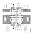
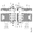
Die Formungseinheit 4 umfasst einen Werkzeugträger 15, der in einen oberen Werkzeugträger 15A und einen unteren Werkzeugträger 15B unterteilt ist. Der obere Werkzeugträger 15A ist an einem oberen Teleskoparm 5A befestigt, der untere Werkzeugträger 15B ist an einem unteren Teleskoparm 5B befestigt. Die Teleskoparme 5A und 5B sind in einer vertikalen Ebene parallel zueinander angeordnet. Wie bereits mit Bezug zu den Fig. 1 und 2 beschrieben, werden sie horizontal bewegt, wobei sie vertikale Schwenkbewegungen entsprechend der Führungsbahn 3 ausführen können. Wenn der obere und der untere Werkzeugträger 15A und 15B, wie in Fig. 9 gezeigt, benachbart zueinander angeordnet sind, wie dies beispielsweise bei dem Formungsabschnitt A der Fall ist, sind der obere und der untere Werkzeugträger 15A und 15B mittels Führungsstangen 22 zueinander ausgerichtet. Geführt von diesen Führungsstangen 22 lassen sich der obere und der untere Werkzeugträger 15A und 15B weiter aufeinander zu bewegen.The forming
Der obere und der untere Werkzeugträger 15A und 15B umfassen jeweils mehrere Führungsbolzen 16A bzw. 16B, welche den oberen Werkzeugträger 15A in zwei oberen Führungsbahnen 3A halten und führen. Die beiden oberen Führungsbahnen 3A sind auf dem gleichen Niveau bei verschiedenen Radien hinsichtlich der Drehbewegung der Antriebseinheit 2 angeordnet. Die unteren Führungsbolzen 16B halten und führen den unteren Werkzeugträger 15B entsprechend in unteren Führungsbahnen 3B. Im vorliegenden Ausführungsbeispiel sind für den oberen und unteren Werkzeugträger 15A und 15B jeweils drei Führungsbolzen 16A bzw. 16B vorgesehen. Sie halten die beiden Werkzeugträgerteile 15A und 15B jeweils in einer horizontalen Position. Von den drei Führungsbolzen 16A bzw. 16B sind jeweils zwei Führungsbolzen 15A bzw. 15B bei der äußeren Führungsbahn 3A bzw. 3B angeordnet und der einzelne Führungsbolzen 16A bzw. 16B bei der inneren Führungsbahn 3A bzw. 3B, um ein sicheres Kurvenverhalten des Werkzeugträgers 15 zu erhalten.The upper and
Der obere und der untere Werkzeugträger 15A und 15B nehmen jeweils dieselbe Anzahl an gleichen Werkzeugen 17 und 18 auf. Des Weiteren ist zwischen dem oberen Werkzeugträger 15A und dem unteren Werkzeugträger 15B ein Matrizengitter 19 und ein Verdrängungsschott 38 angeordnet, wie es später im Detail erläutert wird. Sowohl das Matrizengitter 19 als auch das Verdrängungsschott 38 werden mittels der Führungsstangen 22 geführt.The upper and
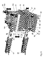
Mit Bezug zu Fig. 10 wird die Kopplung des oberen bzw. unteren Werkzeugträgers 15 an dem Teleskoparm 5 beschrieben:
Der Teleskoparm 5 umfasst zwei zueinander verschiebbare Teile, so dass die Länge des Teleskoparms veränderbar ist. Auf diese Weise lässt sich der radiale Abstand des Werkzeugträgers 15von der Antriebseinheit 2 verändern. An dem radial äußeren Ende desTeleskoparms 5 ist ein Horizontal-/Vertikal-Zweiachsengabelgelenk 23 befestigt. Das Zweiachsen-Gabelgelenk 23 umfasst eine Befestigungseinheit 24, welche an dem radial äußeren Ende desTeleskoparms 5 befestigt ist. Ander Befestigungseinheit 24 ist über einen Bolzen 25das Horizontalgelenk 26 des Zweiachsengabelgelenks 23 befestigt.Das Horizontalgelenk 26 ist um die Achse des Bolzens 25 in einer ersten Ebene schwenkbar. Bei der Anordnung des Teleskoparms 5 in der erfindungsgemäßen Vorrichtung ist diese erste Ebene horizontal ausgerichtet. Andem Horizontalgelenk 26 ist über einen weiteren Bolzen 27das Vertikalgelenk 28 des Zweiachsengabelgelenks 23 befestigt.Das Vertikalgelenk 28 ist in einer zweiten Ebene schwenkbar, die zur ersten Ebene senkrecht ist. Bei der Anordnung des Teleskoparms 5 in der erfindungsgemäßen Vorrichtungist das Vertikalgelenk 28 in einer vertikalen Ebene schwenkbar. Andem Vertikalgelenk 28 ist schließlich der obere oder der untere Werkzeugträger 15A bzw. 15B befestigt.Das Zweiachsengabelgelenk 23 stellt somit eine feste Verbindung zwischendem Teleskoparm 5 und dem entsprechenden Teil des Werkzeugträgers 15 bereit. Auf diese Weise kann der Werkzeugträger 15 störungsfrei und reibungslos alle Positionen in allen drei Raumachsen innerhalb des Weges der Führungsbahn 3 erreichen.- Da die
Antriebseinheit 2 das einzige motorgetriebene Glied der erfindungsgemäßen Vorrichtung hinsichtlich der Bewegung der Formungseinheiten 4 darstellt, gewährleisten dieTeleskoparme 5, dass die Kraft der Antriebseinheit 2 auf die mit ihnen verbundenen Werkzeugträger 15 übertragen wird, so dass diese sich auf der vorgegebenen Führungsbahn 3 bewegen können. Das Zweiachsen-Gabelgelenk 23 und die vertikale Schwenkbarkeit des Teleskoparms 5 gewährleisten dabei, dass jede einzelne Bewegung der Werkzeugträger 15 auf der Führungsbahn 3 kraftübertragend ausgeglichen werden kann. - Mit Bezug zu den Fig. 11
bis 13 wird die Führung des unterenWerkzeugträgers 15B inder Führungsbahn 3B erläutert:Die unteren Führungsbolzen 16B umfassen einen Pilzkopf 29, der in allenAbschnitten der Führungsbahn 3 außer dem Formungsabschnitt A (Fig. 2) ineiner Kulissenführung 33 gehalten und geführt wird. Diese Kulissenführung ist in Fig. 13 dargestellt. Die Lagerung und Führung im Formungsabschnitt A ist in den Fig. 11 und 12 dargestellt. Bei diesem Abschnitt A verlässt derFührungsbolzen 16B die Kulissenführung 33 und wird von einem Führungsrollensystem geführt und gehalten. Das Führungsrollensystem umfasst eng nebeneinander angeordnete Führungsrollen 30, die inRichtung der Führungsbahn 3B drehbar sind. Die Stirnfläche des Pilzkopfes 29 liegt immer auf jeweils zwei Führungsrollen 30 auf, um einen ruhigen Lauf des unterenWerkzeugträgers 15B zu gewährleisten. Um dieFührungsbolzen 16B in seitlicher Position zu halten, sind zwei Seitenführungsplatten 32 beidseitig zudem Pilzkopf 29 desFührungsbolzens 16B angeordnet.- Für jede einzelne Führungsrolle 30 ist eine separat ansteuerbare Niveauregelung 31 vorgesehen, welche die
Führungsrolle 30 in ihrer Höhe verfahren bzw. justieren kann. Hierdurch können die Endverformungskräfte geregelt werden. Auf diese Weise kann sichergestellt werden, dass die Formlinge exakt die gewünschten Festigkeiten aufweisen.Die Niveauregelung 31 kann hierfür mit einer Wägezelleneinheit gekoppelt sein, welche sich andie Kamerainspektionsstation 7 anschließt. Die Wägezelleneinheit kann eine speicherprogrammierbare Steuerung aufweisen, um eine Regelgröße andie Niveauregelung 31 zu übertragen, um die Eintauchtiefen der einzelnen Werkzeuge 17 bzw. 18 zu regeln, wodurch eine Massenveränderung der einzelnen Formlinge erreicht wird, wie es später erläutert wird. - Die Lagerung und Führung des oberen Werkzeugträgers 15A über die
oberen Führungsbolzen 16A inden oberen Führungsbahnen 3A entspricht im Wesentlichen der Führung und der Lagerung des unterenWerkzeugträgers 15B.Der Pilzkopf 29 des oberen Führungsbolzens 16A wird von einerKulissenführung 33der oberen Führungsbahn 3A aufgenommen. Im Unterschied zu der Führung der unterenFührungsbolzen 16B ist jedoch auch im FormungsabschnittA eine Kulissenführung 33 vorgesehen, da es nicht erforderlich ist, sowohlden unteren Werkzeugträger 15B als auchden oberen Werkzeugträger 15A in vertikaler Richtung zu justieren. - Mit Bezug zu den Fig. 14
bis 19 werden verschiedene Beispiele für Werkzeuge 17, 18 und derenBefestigung im Werkzeugträger 15A bzw. 15B erläutert. Die Fig. 14bis 19 zeigen dieWerkzeuge 18, welche andem unteren Werkzeugträger 15B befestigt sind.Die Werkzeuge 17 können identisch oder ähnlich zuden Werkzeugen 18 ausgebildet sein und auf gleiche Weise andem oberen Werkzeugträger 15A befestigt sein. Die Werkzeuge 17 bzw. 18 sind stempelartig ausgebildet. Sie weisen eine Stirnfläche 35 auf, welche, wie in den Fig.14A bis 16A gezeigt, entsprechend der gewünschten Formlingsoberfläche gewählt ist.Die Werkzeuge 17 bzw. 18 sindim Werkzeugträger 15A schwimmend, einfach oder zweifach mittels internen Sicherungsstangen 34 gegen ein Herausfallen gesichert.Eine Sicherungsstange 34 sichert dabei eine Reihemit Werkzeugen 17 bzw. 18. Dies ermöglicht eine sehr dichte Anordnung der Werkzeuge 17 bzw. 18. DieAnzahl der Sicherungsstangen 34 richtet sich nach dem Einsatzzweck der Werkzeuge 17 bzw. 18 und über deren Funktion.- In Fig. 18
ist ein Spezialwerkzeug 36 gezeigt. Es umfasst Heiz-oder Kühlbohrungen 37, in welches ein Fluid eingeleitet werden kann,um das Werkzeug 36 zu heizen oder zu kühlen. - Mit Bezug zu Fig. 20 werden die mit
dem oberen Werkzeugträger 15A verbundenen Teile erläutert:- Die radial innere Seite des oberen
Werkzeugträgers 15A istüber das Zweiachsengabelgelenk 23mit dem Teleskoparm 5A verbunden, wie es mit Bezug zu Fig. 10 erläutert wurde. Die obere Seite des oberenWerkzeugträgers 15A ist überden oberen Führungsbolzen 16A inder Kulissenführung 33 der oberen Führungsbahn 3A gelagert. Ferner sind die Werkzeuge 17 über dieSicherungsstangen 34 in der unteren Seite des oberen Werkzeugträgers 15A gelagert, wie es mit Bezug zu den Fig. 14bis 19 erläutert wurde. - Schließlich
ist das Verdrängungsschott 38 mitdem oberen Werkzeugträger 15A überden Verbindungsmechanismus 41 gekoppelt.Der Verbindungsmechanismus 41umfasst eine Feder 42, welchedas Verdrängungsschott 38 in derRuhelage der Feder 42 so hält, dass die obere Fläche des Verdrängungsschotts 38 beabstandet zu der unteren Fläche des oberen Werkzeugträgers 15A ist. Gegen die Kraft derFeder 42kann das Verdrängungsschott 38 vertikal in Richtungdes oberen Werkzeugträgers 15A bewegt werden. Das Verdrängungsschott 38 ist im Detail in Fig. 21 gezeigt. Es umfasst ein Gitter, bei dem die Öffnungen desGitters von Seitenbegrenzungen 39 des Verdrängungsschotts 38 abgegrenzt sind. Bei der in Fig. 21 gezeigten rechteckigen Gitterstruktur wird jede Öffnung des Gitters von vier Seitenwänden abgegrenzt. Die Unterseite des Gitters des Verdrängungsschotts 38 weist eine gitterartige Stirnfläche 40 auf. Schließlichweist das Verdrängungsschott 38Bohrungen 44 für dieFührungsstangen 22 des Werkzeugträgers 15 auf (Fig. 9).- Mit Bezug zu Fig. 22 werden die mit
dem unteren Werkzeugträger 15B gekoppelten Teile erläutert:Der untere Werkzeugträger 15B istüber das Zweiachsengabelgelenk 23 mitdem unteren Teleskoparm 5B gekoppelt, wie es mit Bezug zu Fig. 10 erläutert wurde. Die untere Seite des unterenWerkzeugträgers 15B ist über dieunteren Führungsbolzen 16B über dieKulissenführung 33 bzw. über das mit Bezug zu Fig. 11 erläuterte Führungsrollensystem geführt und gelagert. Des Weiteren sind die Werkzeuge 18 über dieSicherungsstangen 34 in der oberen Seite des unterenWerkzeugträgers 15B gelagert.- Schließlich
ist das Matrizengitter 19 überden höhenverstellbaren Verbindungsmechanismus 46 mitdem unteren Werkzeugträger 15B gekoppelt.Das Matrizengitter 19umfasst Aufnahmeräume 21, welchevon Seitenbegrenzungen 20 abgegrenzt sind. Die unteren Öffnungen der Aufnahmeräume 21 desMatrizengitters 19 werden durch die indie Aufnahmeräume 21 hineinragenden Werkzeuge 18 verschlossen. Da das Volumen des Aufnahmeraums 21 das Volumen des zu bildenden Formlings bestimmt und damit bei einer bestimmten Dichte auch die Masse bzw. das Gewicht, kann über die Höheneinstellung der Werkzeuge 18 die Masse bzw. das Gewicht der Formlinge eingestellt werden. - Eine Aufsicht
auf das Matrizengitter 19 ist in Fig. 23 gezeigt. Es ist die rechteckige Gitterstruktur erkennbar, welchevon der Stirnfläche 45 desMatrizengitters 19 gebildet wird. Des Weiteren sind dieStirnseiten 35der Werkzeuge 18 erkennbar, welche indie Aufnahmeräume 21 hineinragen und die über dieSicherungsstangen 34 indem unteren Werkzeugträger 15B gehalten werden. Schließlich sind in dem Matrizengitter Bohrungen für dieFührungsstangen 22 vorgesehen. - Da sich die Werkzeuge 17 in
dem Verdrängungsschott 38 bewegen und dieWerkzeuge 18 inden Aufnahmeräumen 21 desMatrizengitters 19 befinden, werden dieWerkzeuge 17 auch als verdrängungsschottseitige Werkzeuge und dieWerkzeuge 18 als matrizenseitige Werkzeuge bezeichnet. - Mit Bezug zu Fig. 24A wird erläutert, wie die einzelnen Teile der Formungseinheit 4 zusammenwirken,
um das Schmelzeband 14 zu portionieren und inden Aufnahmeräumen 21 desMatrizengitters 19 zu verpressen:- Der Formvorgang erfolgt auf der geraden Strecke des Formungsabschnitts A der Führungsbahn 3 (Fig. 2). Zu Beginn des Formungsabschnitts A wird der obere Teil 4A der Formungseinheit 4, d.h. der obere Werkzeugträger 15A und die damit verbundenen Teile vertikal auf
den unteren Teil 4B der Formungseinheit 4, d.h. der untereWerkzeugträger 15B und die damit verbundenen Teile, zu bewegt. Gleichzeitig wird dasvon der Ausformungsstation 13gebildete Schmelzeband 14dem unteren Teil 4B der Formungseinheit 4 zugeführt. Wie aus Fig. 24A ersichtlich, kommt dabeidas Schmelzeband 14 auf der Oberseite desMatrizengitters 19, d.h. insbesondere auf der Stirnfläche 45, welchevon den Seitenbegrenzungen 20 desMatrizengitters 19 gebildet ist, zum Aufliegen.Das Schmelzeband 14 befindet sich somit oberhalb der Aufnahmeräume 21 desMatrizengitters 19. Der Abstand zwischen der Unterseite des Verdrängungsschotts 38 und der Oberseite des Matrizengitters 19 ist zunächst größer als die Dicke desSchmelzebandes 14, so dass dieses zwischendas Matrizengitter 19und das Verdrängungsschott 38 eingebracht werden kann. Schreitet die Formungseinheit 4 im Formungsabschnitt A angetriebenvon der Antriebseinheit 2 weiter voran, wird der obere Werkzeugträger 15Amit dem Verdrängungsschott 38 weiter abgesenkt, bis die untere Stirnfläche 40 des Verdrängungsschotts 38 die obere Fläche des Schmelzebandes 14 berührt. Beim weiteren Absenken des oberenWerkzeugträgers 15Amit dem Verdrängungsschott 38 wirdnun der Abschnitt 14A des Schmelzebandes 14, der sich zwischen der Stirnfläche 45 desMatrizengitters 19 und der Stirnfläche 40 des Verdrängungsschotts 38 befindet, in Richtung der benachbarten Aufnahmeräume 21 verdrängt, wie dies in den Fig. 25A und 25B bzw. Fig. 26A und 26B gezeigt ist.- Beim Absenken des oberen
Werkzeugträgers 15Amit dem Verdrängungsschott 38 während des Verdrängungsvorgangs des Schmelzebandes 14 verringert sich der Abstand des Verdrängungsschotts 38 zudem oberen Werkzeugträger 15A gegen die Kraft derFedern 42. Gleichzeitig wird durch dieFührungsstangen 22 ein Verkanten des Verdrängungsschotts 38 verhindert. DieStärke der Federn 42 ist so ausgelegt, dass sie ein Einsinken des Verdrängungsschotts 38 indas Schmelzeband 14 zulassen. Dasnachrückende obere Werkzeugteil 15A erhöht dabei den Druck,den das Verdrängungsschott 38auf das Schmelzeband 14 ausübt, mittels der immer weiter zusammenfahrenden Federn 42. Um beim Absenken des Verdrängungsschotts 38auf das Schmelzeband 14 dieSchmelzemassen 14A unter der Stirnfläche 40 des Verdrängungsschotts 38 in alle Richtungen zu verteilen, d.h. zu verdrängen, sind dieKanten der Stirnfläche 40 des Verdrängungsschotts 38 speziell geformt. In Fig. 25Bist ein Verdrängungsschott 38 gezeigt, bei dem die Kanten des Übergangsvon der Stirnfläche 40 zu denSeitenflächen der Seitenbegrenzungen 39 des Verdrängungsschotts 38 abgerundet sind. In Fig. 26B ist ein Verdrängungsschott gezeigt, bei dem diese Kanten abgeschrägt sind. Diese Ausgestaltung der Kanten dient einem verlustfreien und wirtschaftlich optimalen Produktionsablauf. Hierbei sollen alle Materialüberstände indie Aufnahmeräume 21 desMatrizengitters 19 gedrängt werden. Das Verdrängungsschott 38 wird so weit aufdas Matrizengitter 19 zu bewegt, bis dieStirnfläche 40 des Verdrängungsschotts 38 auf der Stirnfläche 45 desMatrizengitters 19 aufliegt.- Wie aus den Fig. 21, 23
und 24 ersichtlich, korrespondiert die geometrische Form des Verdrängungsschotts 38 zu der desMatrizengitters 19. Hierbei ist wesentlich, dass dieSeitenbegrenzung 39 des Verdrängungsschotts 38 zuden Seitenbegrenzungen 20 desMatrizengitters 19 und damit dievon den Seitenbegrenzungen 39 bzw. 20 gebildeten Stirnflächen 40 bzw. 45 korrespondiert. DieseSeitenbegrenzungen 39 und 20 bilden die identische Gitterstruktur.Die Seitenbegrenzung 39 des Verdrängungsschotts 38 besitzt insbesondere dieselbe Dickewie die Seitenbegrenzung 20 desMatrizengitters 19. Fernerfluchten die Seitenbegrenzungen 39 und 20 zueinander. Bei der Bewegung des Verdrängungsschotts 38 inRichtung des Matrizengitters 19 sind dieSeitenbegrenzungen 39 und 20 exakt parallel zueinander ausgerichtet. - Nachdem die
Stirnfläche 40 des Verdrängungsschotts 39 auf der Stirnfläche 45 desMatrizengitters 19 aufliegt, senkt sich der obere Werkzeugträger 15Amit den Werkzeugen 17 weiter ab, ohne dass sich die vertikale Lage des Verdrängungsschotts 38 weiter ändern kann, da es aufdem Matrizengitter 19 aufliegt.Die Werkzeuge 17 werden somit in den Öffnungen des Verdrängungsschotts 38 bewegt. Dabeidienen die Seitenbegrenzungen 39 des Verdrängungsschotts 38 als Führung für dieWerkzeuge 17.Das Verdrängungsschott 38 dient somit als Führungskammer für die sich absenkenden Werkzeuge 17 sowie als Vorkammer für die zu verformende Masse. Durch das Absenken der Werkzeuge 17 wird der Teil des Schmelzebandes 14, der sich nach dem Verdrängen noch zwischenden Seitenbegrenzungen 39 des Verdrängungsschotts 38 oberhalb des Aufnahmeraums 21 desMatrizengitters 19 befindet,von den Stirnflächen 35der Werkzeuge 17 indie Aufnahmeräume 21 desMatrizengitters 19 gebracht. Schließlich wird die sich vollständig indem Aufnahmeraum 21 befindliche Portion des Schmelzebands 14 indem Aufnahmeraum 21 verpresst. - Fig. 27A zeigt die
Kraftverteilung im Aufnahmeraum 21 beim Verpressen. Auf die Schmelzeportionen wird von oben und unten Druck durch dieWerkzeuge 17 und 18 ausgeübt. Von der Seite werden die Portionenvon den Seitenbegrenzungen 20 desMatrizengitters 19 umschlossen. Da auf dieSeitenbegrenzungen 20 der gleiche Druck von jeweils zwei benachbarten Aufnahmeräumen 21 ausgeübt wird, heben sich die anden Seitenbegrenzungen 20 anliegenden Kräfte auf. Aus diesem Grund können dieSeitenbegrenzungen 20 und damit auch dieSeitenbegrenzungen 39 des Verdrängungsschotts 38 sehr dünn ausgestaltet werden, wodurch ein etwaiger Restanteil des Schmelzebandes 14, der nicht verpresst wird, äußerst gering gehalten werden kann. - Der Druck, der
von den Werkzeugen 17 und 18 auf dieSchmelzeportionen 14 ausgeübt wird, kann in Abhängigkeit von den zu bildenden Formlingen gewählt werden. Eine Besonderheit der erfindungsgemäßen Vorrichtung ist, dass die Druckhaltezeit, d.h. das Zeitintervall, bei dem der maximale Druck auf die zu verpressende Masse ausgeübt wird, individuell auf die zu verformende Masse eingestellt und auf diese abgestimmt werden kann. Die Druckhaltezeit kann insbesondere im Vergleich zu herkömmlichen Tablettiermaschinen sehr lang gewählt werden. Sie wird nämlich im Wesentlichen von der Drehgeschwindigkeit der Antriebseinheit 2 und der Länge des geraden Formungsabschnitts A bestimmt. Wird der Formungsabschnitt A sehr lang gewählt, wird der maximal auf die zu formende Masse ausgeübte Druck sehr lange aufrechterhalten. - An dem Formungsabschnitt A schließt sich der Auskühlabschnitt B an. Der obere Teil 4A der Formungseinheit 4 mit
dem oberen Werkzeugträger 15A wird in diesem Abschnitt B wieder in vertikaler Richtung vondem unteren Teil 4B der Formungseinheit 4 mitdem unteren Werkzeugträger 15B entfernt. Die verpressten Formlinge können während der Verweilzeit in dem Auskühlabschnitt B auskühlen. Bei der erfindungsgemäßen Vorrichtung lässt sich dieser Auskühlabschnitt B so lange wählen, dass sichergestellt wird, dass keine unerwünschten inneren Spannungen in den gebildeten Formlingen verbleiben. An den Auskühlabschnitt B schließt sich im AbschnittC die Probenentnahmestation 6 an.Bei dieser Station 6 kann mittels einer randomisierten, speichergesteuerten, einzeln ansteuerbaren Vakuum-Formlings-Entnahmeeinheit jeweils eine bestimmte Anzahl an Formlingen entnommen und einer Kontrollvorrichtung übergeben werden. Die von der Grundgesamtheit entnommenen Formlinge bzw. ihre freien Plätze aufdem unteren Werkzeugträger 15B werden mittels der integrierten speicherprogrammierbaren Steuerung an die Formlingsentnahme-und Kamerainspektionsstation 7 übermittelt, um Fehlkontrollmeldungen zu vermeiden. Die Aufgabe dieser Inprozess-Kontrollstation ist es, die qualitätsbezogene Arbeitsweise der erfindungsgemäßen Vorrichtung zu kontrollieren, sie zu bestätigen bzw. ggf. regulierend in den Verfahrensablauf mittels einer speicherprogrammierbaren Steuerung und entsprechend über dieNiveauregulierung 31 einzugreifen. - An den Abschnitt C
mit der Probenentnahmestation 6 schließt sich der Abschnitt D mit der Formlingsentnahme-und Kamerainspektionsstation 7 an, welche mit Bezug zu Fig. 28 erläutert wird. Hierbei wird mittels einer 100 % Online-Sichtkontrolle die Ausschussware 7Bvon der Gutware 7A separiert (vgl. Fig. 2). - Zu Beginn des Abschnitts D werden die
Werkzeuge 18 vollständig inden Aufnahmeraum 21 desMatrizengitters 19 hinein gefahren, so dass die gebildeten Formlinge 57aus dem Matrizengitter 19 herausgedrückt werden und zur Entnahme bereitliegen. Daraufhin wird die Vakuum-Formling-Entnahmeeinheit 58 zwischenden oberen Werkzeugträger 15A unddem unteren Werkzeugträger 15B geschwenkt, so dass sich Vakuum-Aufnahmeschläuche des Formlingaufnahmekopfes 59 unmittelbarüber den Formlingen 57 befinden. Die Vakuum-Formling-Entnahmeeinheit 58 hat die gleiche Anzahl an einzeln ansteuerbaren Vakuumschläuchen zur Aufnahme der Formlinge 57wie Werkzeuge 18 und Aufnahmeräume 21 vorgesehen sind. Die Formlinge werden von den Vakuumschläuchen angesogen undvon dem Matrizengitter 19 abgehoben. Daraufhin wird der Formlingaufnahmekopf 59 mittels desMotors 62 und derWelle 61 aus der Formungseinheit 4 herausgeschwenkt, woraufhin dieFormlinge 57 auf einem transparenten Förderband 63 abgesetzt werden.Auf dem Förderband 63 werden dieFormlinge 57 einer Kamerainspektionseinheit mit einer oberen Kamera 64 und einer unteren Kamera 65 zur Untersuchung der Ober- und Unterseite sowie den Seitenrändern der Formlinge 57 zugeführt. Mittels der Kameras 64und 65 kann die Gesamtheit der gebildeten Formlinge 57 optisch untersucht werden. Dabei kann die gesamte geometrische Form der Formlinge 57 untersucht werden. Ferner können dieFormlinge 57 mittels Infrarotspektroskopie, insbesondere NIR-Spektroskopie, berührungsfrei untersucht werden. Da die geometrische Anordnung der Formlinge aufdem Förderband 63 genau derjenigen indem Matrizengitter 19 entspricht, können bei fehlerhaften Formlingen 57 ggf. Rückschlüsse aufFehlproduktion im Matrizengitter 19 ermittelt werden. Die NIR-Spektroskopie arbeitet mit Hilfe chemometrischer Auswerteverfahren an der qualitativen und quantitativen analytischen Sortierung derGutproduktion 7A.- Mittels einer optionalen sich anschließenden Wägezelleneinheit können die Einzelgewichte der Formlinge 57 erfasst werden. Abweichungen von vorgegebenen Gewichtstoleranzen können auf diese Weise erfasst werden und zu einer Aussortierung fehlerhafter Formlinge verwendet werden. Ferner kann die Wägezelleneinheit eine Regelgröße an
die Niveauregelung 31 und/oder an die Führungsrollen, wie bereits erläutert, übertragen. - An den Abschnitt D schließt sich der Abschnitt E
mit der Reinigungsstation 8 an, die mit Bezug zu den Fig. 29, 30A und 30B erläutert wird:- Zwischen
dem oberen Werkzeugträger 15A unddem unteren Werkzeugträger 15B wirdmindestens ein Bürstenkopf 47 mittels eines Bürstenschaftes 50 eingefahren. Am Ende desBürstenschaftes 50ist eine Bürstenkopfaufnahme 49 angebracht, die in Richtungdes oberen Teils 4A und des unteren Teils 4B der Formungseinheit 4Reinigungsborsten 48 aufweist.Der Borstenkopf 47 dreht sich und reinigt auf diese Weise alle Teile, die mit der formbaren Masse in Berührung gekommen sind. Insbesonderewerden das Verdrängungsschott 38 und dieWerkzeuge 17sowie das Matrizengitter 19 und dieWerkzeuge 18 gereinigt. Nach der Reinigung wird der Bürstenschaft 50 aus der Formungseinheit 4 herausgedreht. Hierfür ist er auf einer Dreheinrichtung 51 befestigt, welche drei Bürstenköpfe 47 umfassen kann sowie entsprechende Anzahlen anBürstenschäften 50. Die aus der Formungseinheit 4 herausgedrehten Bürsteschäfte 50 werden danach mittels Druckluft 52 gereinigt, welche überdas Rohrsystem 53A den Druckluftdüsen 53B zugeführt wird. Der gesamte Reinigungsvorgang erfolgt vollautomatisch und ist indie Führungsbahn 3 integriert.Die Reinigungsstation 8 kann während des laufenden Betriebs der sich kontinuierlich bewegenden Formungseinheiten 4 arbeiten.Die Reinigungsstation 8 kann mit unterschiedlichen Bürsten, Druckluft und Absaugvorrichtungen ausgestattet sein. Sie ist voll beweglich in allen drei Koordinatenrichtungen sowie mit Näherungssensoren und - Auswechseleinheiten ausgestattet.
- Zwischen
- Der Formvorgang erfolgt auf der geraden Strecke des Formungsabschnitts A der Führungsbahn 3 (Fig. 2). Zu Beginn des Formungsabschnitts A wird der obere Teil 4A der Formungseinheit 4, d.h. der obere Werkzeugträger 15A und die damit verbundenen Teile vertikal auf
- Die radial innere Seite des oberen
- The
telescopic arm 5 comprises two mutually displaceable parts, so that the length of the telescopic arm is variable. In this way, the radial distance of the tool carrier 15 from thedrive unit 2 can be changed. At the radially outer end of thetelescopic arm 5, a horizontal / vertical two-axis fork joint 23 is attached. The two-axis fork joint 23 comprises a fixingunit 24, which is fastened to the radially outer end of thetelescopic arm 5. At thefastening unit 24 is via abolt 25, the horizontal joint 26 of the two-axle joint 23 attached. The horizontal joint 26 is pivotable about the axis of thebolt 25 in a first plane. In the arrangement of thetelescopic arm 5 in the device according to the invention, this first plane is aligned horizontally. At the horizontal joint 26, the vertical joint 28 of the two-axis fork joint 23 is attached via afurther bolt 27. The vertical joint 28 is pivotable in a second plane, which is perpendicular to the first plane. In the arrangement of thetelescopic arm 5 in the device according to the invention, the vertical joint 28 is pivotable in a vertical plane. Finally, the upper orlower tool carrier telescopic arm 5 and the corresponding part of the tool carrier 15. In this way, the tool holder 15 can smoothly and smoothly reach all positions in all three spatial axes within the path of theguideway 3. - Since the
drive unit 2 represents the only motor-driven member of the device according to the invention with regard to the movement of the formingunits 4, thetelescopic arms 5 ensure that the force of thedrive unit 2 is transmitted to the tool carriers 15 connected to them so that they move on thepredetermined guide track 3 can. The two-axis fork joint 23 and the vertical pivoting of thetelescopic arm 5 ensure that each individual movement of the tool carrier 15 can be compensated for transmitting force on theguideway 3. - With reference to FIGS. 11 to 13, the guidance of the
lower tool carrier 15B in theguide track 3B will be explained.- The lower guide pins 16B comprise a
mushroom head 29 which is held and guided in all sections of theguide track 3 except for the shaping section A (FIG. 2) in a slottedguide 33. This slotted guide is shown in Fig. 13. The storage and guidance in the forming section A is shown in FIGS. 11 and 12. In this section A, theguide pin 16B leaves theslide guide 33 and is guided and held by a guide roller system. The guide roller system comprises closely spacedguide rollers 30 which are rotatable in the direction of theguide track 3B. The face of themushroom head 29 always lies on each twoguide rollers 30 to ensure a smooth running of thelower tool carrier 15B. In order to keep the guide pins 16B in lateral position, twoside guide plates 32 are arranged on both sides of themushroom head 29 of theguide pin 16B. - For each
individual guide roller 30, a separatelycontrollable level control 31 is provided, which can move or adjust the height of theguide roller 30. As a result, the Endverformungskräfte be regulated. In this way it can be ensured that the blanks have exactly the desired strength. For this purpose, thelevel control 31 can be coupled to a weighing cell unit, which adjoins thecamera inspection station 7. The load cell unit may have a programmable logic controller to transmit a controlled variable to thelevel control 31 to control the immersion depths of theindividual tools - The mounting and guiding of the
upper tool carrier 15A over the upper guide pins 16A in the upper guide tracks 3A essentially corresponds to the guidance and the mounting of thelower tool carrier 15B. Themushroom head 29 of theupper guide pin 16A is received by a slottedguide 33 of theupper guide track 3A. In contrast to the guidance of the lower guide pins 16B, however, a slottedguide 33 is also provided in the shaping section A, since it is not necessary to adjust both thelower tool carrier 15B and theupper tool carrier 15A in the vertical direction. - With reference to FIGS. 14 to 19, various examples of
tools tool carrier tools 18 which are fixed to thelower tool carrier 15B. Thetools 17 may be identical or similar to thetools 18 and similarly secured to theupper tool carrier 15A. - The
tools end face 35 which, as shown in Figs. 14A to 16A, corresponding to the desired Mold surface is selected. Thetools tool carrier 15A, secured once or twice by means of internal locking bars 34 against falling out. This ensures a very dense arrangement of thetools rods 34 depends on the intended use of thetools - In Fig. 18, a
special tool 36 is shown. It includes heating or cooling holes 37 into which a fluid may be introduced to heat or cool thetool 36. - Referring to Fig. 20, the parts connected to the
upper tool carrier 15A will be explained.- The radially inner side of the
upper tool carrier 15A is connected to thetelescopic arm 5A via the two-axis fork joint 23, as explained with reference to FIG. The upper side of theupper tool carrier 15A is mounted on theupper guide pin 16A in the slottedguide 33 of theupper guide track 3A. Further, thetools 17 are mounted on the securingrods 34 in the lower side of theupper tool carrier 15A, as explained with reference to FIGS. 14 to 19. - Finally, the
displacement barrier 38 is coupled to theupper tool carrier 15A via theconnection mechanism 41. Thelinkage mechanism 41 includes aspring 42 which holds thedisplacement bulkhead 38 in the rest position of thespring 42 so that the upper surface of thedisplacement bulkhead 38 is spaced from the lower surface of theupper tool carrier 15A. Against the force of thespring 42, thedisplacement barrier 38 can be moved vertically in the direction of theupper tool carrier 15A. - The
displacement barrier 38 is shown in detail in FIG. 21. It comprises a grid in which the openings of the grid are delimited bylateral boundaries 39 of thedisplacement bulkhead 38. In the rectangular grid structure shown in Fig. 21, each opening of the grid is demarcated by four side walls. The bottom of the Grid of thedisplacement bulkhead 38 has a grid-like end face 40. Finally, thedisplacement barrier 38 hasbores 44 for theguide rods 22 of the tool carrier 15 (FIG. 9). - Referring to Fig. 22, the parts coupled to the
lower tool carrier 15B will be explained.- The
lower tool carrier 15B is coupled to the lowertelescopic arm 5B via the two-axis fork joint 23, as explained with reference to FIG. The lower side of thelower tool carrier 15B is guided and supported via the lower guide pins 16B via the slottedguide 33 or via the guide roller system explained with reference to FIG. 11. Furthermore, thetools 18 are mounted on the securingrods 34 in the upper side of thelower tool carrier 15B. - Finally, the
die grid 19 is coupled via the height-adjustable link mechanism 46 to thelower tool carrier 15B. Thematrix grid 19 includes receivingspaces 21, which are delimited fromlateral boundaries 20. The lower openings of the receivingspaces 21 of thedie grid 19 are closed by thetools 18 projecting into the receivingspaces 21. Since the volume of the receivingspace 21 determines the volume of the molding to be formed and thus at a certain density and the mass or weight, the mass or the weight of the moldings can be adjusted via the height adjustment of thetools 18. - A plan view of the
die grid 19 is shown in FIG. The rectangular grid structure can be seen, which is formed by theend face 45 of thedie grid 19. Furthermore, the end faces 35 of thetools 18 can be seen, which protrude into the receivingspaces 21 and which are held over the securingrods 34 in thelower tool carrier 15B. Finally, bores for theguide rods 22 are provided in the matrix grid. - Since the
tools 17 move in thedisplacement barrier 38 and thetools 18 are located in the receivingspaces 21 of thedie grid 19, theTools 17 also referred to as displacement bulkhead-side tools and thetools 18 as a die-side tools. - With reference to FIG. 24A, it is explained how the individual parts of the
shaping unit 4 cooperate in order to portion themelt belt 14 and to press it into the receivingspaces 21 of the die grid 19:- The molding operation takes place on the straight path of the molding section A of the guide track 3 (FIG. 2). At the beginning of the molding section A, the
upper part 4A of themolding unit 4, that is, theupper tool carrier 15A and the parts connected thereto are vertically moved toward thelower part 4B of themolding unit 4, ie thelower tool carrier 15B and the parts connected thereto. At the same time, themelt belt 14 formed by the formingstation 13 is supplied to thelower part 4B of themolding unit 4. As can be seen from FIG. 24A, themelt belt 14 comes to lie on the upper side of thedie grid 19, ie in particular on theend face 45, which is formed by the side delimitations 20 of thedie grid 19. Themelt strip 14 is thus located above the receivingspaces 21 of thedie grid 19. The distance between the bottom of thedisplacement bulkhead 38 and the top of thedie grid 19 is initially greater than the thickness of themelt belt 14, so that this introduced between thedie grid 19 and thedisplacement barrier 38 can be. - As the forming
unit 4 continues to advance in the forming section A driven by thedrive unit 2, theupper tool carrier 15A is further lowered with thedisplacement bulkhead 38 until thelower end face 40 of thedisplacement bulkhead 38 contacts the upper surface of themelt belt 14. Upon further lowering of theupper tool carrier 15A with thedisplacement bulkhead 38, theportion 14A of themelt belt 14, which is located between theend face 45 of thedie grid 19 and theend face 40 of thedisplacement bulkhead 38, is now displaced in the direction of the adjacent receivingspaces 21, as shown in FIGS Figs. 25A and 25B and Figs. 26A and 26B, respectively. - When lowering the
upper tool carrier 15A with thedisplacement barrier 38 during the displacement process of themelt belt 14 reduces the Distance of thedisplacement bulkhead 38 to theupper tool carrier 15A against the force of thesprings 42. At the same time, tilting of thedisplacement bulkhead 38 is prevented by theguide rods 22. The strength of thesprings 42 is designed so that they allow a sinking of thedisplacement bulkhead 38 in themelt belt 14. The nachrückendeupper tool part 15A increases the pressure exerted by thedisplacement barrier 38 on themelt belt 14, by means of the ever closer together springs 42. To lower thedisplacement bulkhead 38 on themelt belt 14, themelt masses 14A under theend face 40 of thedisplacement bulkhead 38 in all To distribute directions, ie to displace, the edges of theend face 40 of thedisplacement bulkhead 38 are specially shaped. In Fig. 25B, adisplacement barrier 38 is shown in which the edges of the transition from theend face 40 to the side surfaces of theside boundaries 39 of thedisplacement bulkhead 38 are rounded. Shown in Fig. 26B is a displacement barrier in which these edges are chamfered. This configuration of the edges serves a lossless and economically optimal production process. In this case, all material supernatants are to be forced into the receivingspaces 21 of thedie grid 19. - The
displacement bulkhead 38 is moved toward thedie grid 19 until theend face 40 of thedisplacement bulkhead 38 rests on theend face 45 of thedie grid 19. - As can be seen in FIGS. 21, 23 and 24, the geometric shape of the
displacement bulkhead 38 corresponds to that of thedie grid 19. It is essential that theside boundary 39 of thedisplacement bulkhead 38 be aligned with theside boundaries 20 of thedie grid 19 and thus with theside boundaries side boundaries side boundary 39 of thedisplacement bulkhead 38 has in particular the same thickness as theside boundary 20 of thedie grid 19. Furthermore, theside boundaries displacement bulkhead 38 in the direction of thedie grid 19, theside boundaries - After the
end face 40 of thedisplacement bulkhead 39 rests on theend face 45 of thedie grid 19, theupper tool carrier 15A further lowers with thetools 17, without the vertical position of thedisplacement bulkhead 38 being able to continue to change since it rests on thedie grid 19. Thetools 17 are thus moved in the openings of thedisplacement bulkhead 38. The side delimitations 39 of thedisplacement bulkhead 38 serve as a guide for thetools 17. Thedisplacement bulkhead 38 thus serves as a guide chamber for the loweringtools 17 as well as an antechamber for the mass to be deformed. By lowering thetools 17 of the part of themelt belt 14, which is still displaced between theside boundaries 39 of thedisplacement 38 above the receivingspace 21 of thematrix grid 19, brought from the end faces 35 of thetools 17 into the receivingspaces 21 of thematrix grid 19 , Finally, the portion of themelt belt 14 located completely in the receivingspace 21 is pressed in the receivingspace 21. - Fig. 27A shows the distribution of force in the receiving
space 21 during pressing. On the melt portions pressure is exerted by thetools side boundaries 20 of thematrix grid 19 are enclosed. Since the same pressure is exerted on thelateral boundaries 20 by twoadjacent receiving chambers 21, the forces applied to thelateral boundaries 20 cancel each other out. For this reason, theside boundaries 20 and thus also theside boundaries 39 of thedisplacement bulkhead 38 can be made very thin, whereby a possible residual portion of themelt belt 14, which is not compressed, can be kept extremely low. - The pressure exerted by the
tools melt portions 14 can be selected depending on the moldings to be formed. A special feature of the device according to the invention is that the pressure-holding time, ie the time interval at which the maximum pressure is exerted on the mass to be pressed, can be adjusted individually to the mass to be deformed and adapted to it. The pressure holding time can be chosen to be very long, in particular in comparison to conventional tableting machines. In fact, it is essentially dependent on the rotational speed of thedrive unit 2 and the length of the straight forming section A determines. If the forming section A is chosen to be very long, the maximum pressure exerted on the mass to be formed is maintained for a very long time. - At the forming section A, the cooling section B connects. The
upper part 4A of the formingunit 4 with theupper tool carrier 15A is again removed in this section B in the vertical direction from thelower part 4B of the formingunit 4 with thelower tool carrier 15B. The compressed moldings can cool during the residence time in the cooling section B. In the device according to the invention, this cooling section B can be chosen so long that it is ensured that no unwanted internal stresses remain in the formed products. The cooling station B is followed by thesampling station 6 in the section C. In thisstation 6 can each be removed by means of a randomized, memory-controlled, individually controllable vacuum blank removal unit a certain number of moldings and transferred to a control device. The blanks removed from the population or their free spaces on thelower tool carrier 15B are transmitted to the blank removal andcamera inspection station 7 by means of the integrated programmable logic controller in order to avoid false control messages. The task of this in-process control station is to control the quality-related operation of the device according to the invention, to confirm it or, if necessary, to intervene in the process sequence by means of a programmable logic controller and correspondingly via thelevel control 31. - The section C with the
sampling station 6 is followed by the section D with the blank removal andcamera inspection station 7, which will be explained with reference to FIG. 28. In this case, by means of a 100% online visual inspection, the rejectedgoods 7B are separated from thegoods 7A (see Fig. 2). - At the beginning of section D, the
tools 18 are moved completely into the receivingspace 21 of thedie grid 19, so that the shapedarticles 57 formed are pushed out of thedie grid 19 and ready for removal. Thereafter, the vacuumblank removal unit 58 between theupper Tool carrier 15 A and thelower tool carrier 15 B pivoted so that vacuum receiving hoses of themolding receiving head 59 are located directly above themoldings 57. The vacuummolding removal unit 58 has the same number of individually controllable vacuum hoses for receiving themoldings 57 astools 18 and receivingspaces 21 are provided. The moldings are sucked in by the vacuum hoses and lifted off thedie grid 19. Subsequently, themolding receiving head 59 is swung out of themolding unit 4 by means of themotor 62 and theshaft 61, whereupon themoldings 57 are deposited on atransparent conveyor belt 63. On theconveyor belt 63, themoldings 57 of a camera inspection unit with anupper camera 64 and alower camera 65 for examination of the top and bottom and the side edges of themoldings 57 are supplied. - By means of the
cameras moldings 57 can be optically examined. In this case, the entire geometric shape of themoldings 57 can be examined. Furthermore, themoldings 57 can be examined without contact by means of infrared spectroscopy, in particular NIR spectroscopy. Since the geometrical arrangement of the blanks on theconveyor belt 63 corresponds exactly to that in thedie grid 19, conclusions as to defective production in thedie grid 19 can be determined fordefective blanks 57. The NIR spectroscopy works with the help of chemometric evaluation methods on the qualitative and quantitative analytical sorting of thegood production 7A. - By means of an optional subsequent weighing cell unit, the individual weights of the
moldings 57 can be detected. Deviations from predetermined weight tolerances can be detected in this way and used to sort out faulty blanks. Furthermore, the weighing cell unit can transmit a controlled variable to thelevel control 31 and / or to the guide rollers, as already explained. - The section D is followed by the section E with the cleaning
station 8, which will be explained with reference to FIGS. 29, 30A and 30B:- Between the
upper tool carrier 15A and thelower tool carrier 15B at least onebrush head 47 is retracted by means of abrush shaft 50. At the end of thebrush shaft 50, abrush head receptacle 49 is attached, which has cleaning bristles 48 in the direction of theupper part 4A and thelower part 4B of themolding unit 4. Thebristle head 47 rotates, thus cleaning all parts which have come into contact with the moldable mass. In particular, thedisplacement barrier 38 and thetools 17 as well as thedie grid 19 and thetools 18 are cleaned. After cleaning, thebrush shaft 50 is unscrewed from themolding unit 4. For this purpose, it is mounted on arotating device 51, which may comprise three brush heads 47 and corresponding numbers ofbrush shafts 50. Thebrushes 50 turned out of the formingunit 4 are then cleaned by means ofcompressed air 52, which is supplied via thepipe system 53A to the compressed-air nozzles 53B. The entire cleaning process is fully automatic and is integrated in theguideway 3. The cleaningstation 8 may operate during ongoing operation of the continuously moving formingunits 4. The cleaningstation 8 may be equipped with different brushes, compressed air and suction devices. It is fully movable in all three coordinate directions as well as with proximity sensors and - Replacement units equipped.
- Between the
- The molding operation takes place on the straight path of the molding section A of the guide track 3 (FIG. 2). At the beginning of the molding section A, the
- The
- The radially inner side of the
- The lower guide pins 16B comprise a
An den Abschnitt E mit der Reinigungsstation 8 schließt sich der Abschnitt F mit der Formungsraumbeschichtungseinrichtung 9 an, die mit Bezug zu Fig. 31 erläutert wird:
Die Formungsraumbeschichtungseinrichtung 9umfasst ein Rohrsystem 54, mitdem ein Beschichtungsfluid 56 oder einem Beschichtungspulver (Formtrennmittel) zugeführt werden kann.Das Beschichtungsfluid 56 bzw. das Beschichtungspulver tritt beiden Düsen 55 aus. Vorzugsweise entspricht dieAnzahl der Düsen 55 der Anzahl der Werkzeuge 17und 18. DieAufgabe der Formungsraumbeschichtungseinrichtung 9 besteht darin, mögliche Anhaftungstendenzen der unterschiedlichen zu verarbeitenden Materialien zu reduzieren bzw. auszuschalten, um einen reibungslosen Produktionsablauf zu gewährleisten. Hierfür werden die Teile der Vorrichtung, die mit der zu verarbeitenden Masse in Berührung kommen,mit dem Beschichtungsfluid 56 bzw. das Beschichtungspulver beschichtet. Die Wahl des Beschichtungsfluids hängt von der zu formenden Masse und dem beabsichtigten Einsatzgebiet der zu bildenden Formlinge 57 ab.- Nach dem
Passieren der Formungsraumbeschichtungseinrichtung 9 im Abschnitt F werden dieFormungseinheiten 4 zum erneuten Bilden von Formlingen dem Formungsabschnitt A auf der Führungsbahn 3 zugeführt. - Gemäß einem zweiten Ausführungsbeispiel der vorliegenden Erfindung wird die formbare Masse, aus welcher die
Formlinge 57 gebildet werden, nicht mittels der Extrusionstechnologie gebildet. Vielmehr handelt es sich bei diesem Ausführungsbeispiel bei der formbaren Masseum ein Schüttgut 14B beliebiger Zusammensetzung.Das Schüttgut 14B ist insbesondere pulverförmig, fließfähig und formbar. Es kann sich beispielsweise um ein pulverförmiges Granulat handeln. Die erfindungsgemäße Vorrichtung kann vorteilhafterweise insbesondere fürein Schüttgut 14B z.B. aus der Granulattechnologie eingesetzt werden, welches sehr schlecht verformbar ist, da die Druckhaltezeit bei der erfindungsgemäßen Vorrichtung auf einen sehr langen Zeitraum eingestellt werden kann. - Da bei dem zweiten
Ausführungsbeispiel das Schüttgut 14B direkt indie Aufnahmeräume 21 desMatrizengitters 19 gefüllt werden kann,könnte das Verdrängungsschott 38 bei der Vorrichtung des zweiten Ausführungsbeispiels weggelassen werden. Vorzugsweise dient es jedoch weiterhin der Führung der Werkzeuge 17.Das Schüttgut 14B wird bei dem zweiten Ausführungsbeispiel mittels einer an sich bekannten Einrichtung, wie sie beispielsweise bei herkömmlichen Tablettiermaschinen verwendet wird, direkt indie Aufnahmeräume 21 gefüllt, wie es in Fig. 24B dargestellt ist. Bei der Einrichtung kann es sich z.B. um eine Pulververteilanlage zum gleichmäßigen Austragen von fließfähigen, formbaren,pulverförmigen Schüttgütern 14B handeln, bei welcher dieSchüttgüter 14B kontinuierlich zuführbar sind. Nach dem Befüllen der Aufnahmeräume 21 erfolgt das Verpressen durch dieWerkzeuge 17 und 18 (vgl. Fig. 27B) sowie die weiteren Verfahrensschritte, wie es vorstehend beschrieben wurde. - Bei dem zweiten Ausführungsbeispiel ist es besonders wichtig, dass die während des Formungsvorgangs entstandene Druckenergie über einen längeren Zeitraum auf die zu formende Masse übertragen wird, d.h. ein hoher Druck wird über einen längeren Zeitraum auf die zu formende Masse ausgeübt, um hierdurch den materialspezifischen Rückstellkräften der zu verformenden Massen entgegenzuwirken. Ferner kann der Druck auch während des Auskühlabschnitts B aufrechterhalten werden, indem der obere Teil 4A und der untere Teil 4B der Formungseinheit 4 erst nach diesem Auskühlabschnitt B auseinander fahren. Auf diese Weise werden Massen mit erhöhten elastischen Rückstellkräften bis zum Erstarren bzw. Erkalten in der Plastifizierungsposition gehalten.
- The molding
space coating device 9 comprises apipe system 54, with which acoating fluid 56 or a coating powder (mold release agent) can be supplied. Thecoating fluid 56 or the coating powder exits at thenozzles 55. Preferably, the number ofnozzles 55 corresponds to the number oftools space coating device 9 is to reduce or eliminate possible adhesion tendencies of the different materials to be processed in order to ensure a smooth production process. For this purpose, the parts of the device which come into contact with the mass to be processed, coated with thecoating fluid 56 and the coating powder. The choice of coating fluid depends on the mass to be formed and the intended area of use of themoldings 57 to be formed. - After passing the forming
space coating device 9 in the section F, the formingunits 4 for re-forming moldings are fed to the forming section A on theguide track 3. - According to a second embodiment of the present invention, the moldable mass from which the
moldings 57 are formed is not formed by extrusion technology. Rather, in this exemplary embodiment, the mouldable mass is abulk material 14B of arbitrary composition. Thebulk material 14B is in particular powdery, flowable and moldable. It may be, for example, a powdered granules. The device according to the invention can advantageously be used in particular for abulk material 14B, for example, from the granule technology, which is very poorly deformable, since the pressure holding time in the device according to the invention can be set to a very long period. - In the second embodiment, since the
bulk material 14B can be directly filled in theaccommodation spaces 21 of thedie grid 19, thedisplacement bulkhead 38 in the apparatus of the second embodiment could be omitted. Preferably, however, it still serves to guide thetools 17. Thebulk material 14B is filled in the second embodiment by means of a per se known device, as used for example in conventional tableting machines, directly into the receivingspaces 21, as shown in Fig. 24B , The device can be, for example, a powder distribution system for the uniform discharge of flowable, formable, powderybulk materials 14B, in which thebulk materials 14B can be continuously fed. After filling the receivingspaces 21, the pressing is carried out by thetools 17 and 18 (see Fig. 27B) and the further process steps, as described above. - In the second embodiment, it is particularly important that the pressure energy generated during the molding process be sustained over a long period of time the mass to be molded is transferred, ie a high pressure is exerted over a longer period of time on the mass to be formed, thereby counteracting the material-specific restoring forces of the masses to be deformed. Further, the pressure can be maintained even during the Auskühlabschnitts B by the
upper part 4A and thelower part 4B of the formingunit 4 apart only after this Auskühlabschnitt B apart. In this way, masses are held with increased elastic restoring forces until solidification or cooling in the plasticizing position.
- 11
- Extruderextruder
- 22
- Antriebseinheitdrive unit
- 33
- Führungsbahnguideway
- 3A3A
- oberer Teil der Führungsbahnupper part of the guideway
- 3B3B
- unterer Teil der Führungsbahnlower part of the guideway
- 44
- Formungseinheitshaping unit
- 4A4A
- oberer Teil der Formungseinheitupper part of the molding unit
- 4B4B
- unterer Teil der Formungseinheitlower part of the molding unit
- 55
- Teleskoparmtelescopic arm
- 5A5A
- oberer TeleskoparmUpper telescopic arm
- 5B5B
- unterer Teleskoparmlower telescopic arm
- 66
- ProbenentnahmestationSampling station
- 77
- Formlingsentnahme- und KamerainspektionsstationBlank removal and camera inspection station
- 7A7A
- GutwareGutware
- 7B7B
- Ausschusswarereject goods
- 88th
- Reinigungsstationcleaning station
- 99
- FormungsraumbeschichtungseinrichtungMolding space coating device
- 1010
- Extruderdüseextruder
- 1111
- Schmelzestrangmelt strand
- 12A und 12B12A and 12B
- Walzen der AusformungsstationRolling the forming station
- 1313
- Ausformungsstationmolding station
- 1414
- Schmelzebandmelt tape
- 14A14A
- Abschnitt des Schmelzebandes zwischen den Stirnflächen des Matrizengitters und des VerdrängungsschottsSection of the melt ribbon between the faces of the die grid and the displacement bulkhead
- 14B14B
- fließfähiges, formbares pulverförmiges Schüttgutflowable, malleable powdered bulk material
- 1515
- Werkzeugträgertool carrier
- 15A15A
- oberer Werkzeugträgerupper tool carrier
- 15B15B
- unterer Werkzeugträgerlower tool carrier
- 1616
- Führungsbolzenguide pins
- 16A16A
- obere Führungsbolzenupper guide pins
- 16B16B
- untere Führungsbolzenlower guide pin
- 1717
- obere Werkzeugeupper tools
- 1818
- untere Werkzeugelower tools
- 1919
- Matrizengitterdie grid
- 2020
- Seitenbegrenzungen des MatrizengittersSide boundaries of the matrix grid
- 2121
- Aufnahmeräume des MatrizengittersReception rooms of the Matrizengitters
- 2222
- WerkzeugträgerführungsstangenTool carrier guide rods
- 2323
- ZweiachsengabelgelenkTwo-axis fork joint
- 2424
- Befestigungseinheit des TeleskoparmsFastening unit of the telescopic arm
- 2525
- Bolzenbolt
- 2626
- Horizontalgelenk des ZweiachsengabelgelenksHorizontal joint of the biaxial fork joint
- 2727
- Bolzenbolt
- 2828
- Vertikalgelenk des ZweiachsengabelgelenksVertical joint of the biaxial fork joint
- 2929
- Pilzkopf des FührungsbolzensMushroom head of the guide pin
- 3030
- Führungsrollenguide rollers
- 3131
- Niveauregelung der FührungsrollenLevel control of the guide rollers
- 3232
- Seitenführungsplatten der FührungsbahnSide guide plates of the guideway
- 3333
- Kulissenführung der FührungsbahnSlotted guide of the guideway
- 3434
- Sicherungsstangen für die WerkzeugeSafety bars for the tools
- 3535
- Stirnfläche des WerkzeugsFace of the tool
- 3636
- Spezialwerkzeug mit Heiz- oder KühlbohrungenSpecial tool with heating or cooling holes
- 3737
- Heiz- oder KühlbohrungenHeating or cooling holes
- 3838
- Verdrängungsschottdisplacement partition
- 3939
- Seitenbegrenzungen des VerdrängungsschottsSide boundaries of the displacement bulkhead
- 4040
- Stirnfläche des VerdrängungsschottsEnd face of the displacement bulkhead
- 4141
- Verbindungsmechanismus für das VerdrängungsschottConnecting mechanism for the displacement bulkhead
- 4242
- Federfeather
- 4343
- Anhebevorrichtunglifting device
- 4444
- Bohrungen für die WerkzeugträgerführungsstangenHoles for the tool carrier guide rods
- 4545
- Stirnfläche des MatrizengittersEnd face of the matrix grid
- 4646
- Volumeneinstellmechanismus für das MatrizengitterVolume adjustment mechanism for the die grid
- 4747
- Bürstenkopfbrush head
- 4848
- Reinigungsborstencleaning bristles
- 4949
- BürstenkopfaufnahmeBrush head holder
- 5050
- Bürstenschaftbrush shaft
- 5151
- Dreheinrichtung für die BürstenRotary device for the brushes
- 5252
- Druckluftcompressed air
- 53A53A
- Rohrsystem zum Zuführen der DruckluftPipe system for supplying the compressed air
- 53B53B
- Druckluftdüsecompressed air nozzle
- 5454
- Rohrsystem zum Zuführen des BeschichtungsfluidsPipe system for supplying the coating fluid
- 5555
- Beschichtungsdüsencoating dies
- 5656
- Beschichtungsfluidcoating fluid
- 5757
- Formlingemoldings
- 5858
- Vakuum-Formling-EntnahmeeinheitVacuum molding removal unit
- 5959
- FormlingaufnahmekopfMolding receiving head
- 6060
- ausfahrbarer Arm der Vakuum-Formling-Entnahmeeinheitextendable arm of the vacuum molding extraction unit
- 6161
- Welle der Vakuum-Formling-EntnahmeeinheitWave of the vacuum molding extraction unit
- 6262
- Antrieb der Vakuum-Formling-EntnahmeeinheitDrive the vacuum molding extraction unit
- 6363
- Förderbandconveyor belt
- 6464
- Kamera für die Oberseite der FormlingeCamera for the top of the moldings
- 6565
- Kamera für die Unterseite der FormlingeCamera for the bottom of the moldings
Claims (28)
dadurch gekennzeichnet,
dass die Seitenbegrenzungen (39) des Verdrängungsschotts (38) mit den Seitenbegrenzungen (20) des Matrizengitters (19) fluchten.Device according to claim 1,
characterized,
that the side boundaries (39) of the displacement partition (38) with the side limitation (20) in alignment of the die (19).
dadurch gekennzeichnet,
dass die Seitenbegrenzungen (39) des Verdrängungsschotts (38) und die Seitenbegrenzungen (20) des Matrizengitters (19) Stirnflächen (40, 45) aufweisen, die zumindest zum Teil zur Anlage kommen, wenn das Verdrängungsschott (38) und das Matrizengitter (19) vollständig aufeinander zu bewegt sind.Apparatus according to claim 1 or 2,
characterized,
in that the side boundaries (39) of the displacement bulkhead (38) and the side boundaries (20) of the die grid (19) have end faces (40, 45) which at least partially come into contact when the displacement bulkhead (38) and the die grid (19) are completely moved towards each other.
dadurch gekennzeichnet,
dass der Übergang von der Stirnfläche (40) zu den Seitenbegrenzungen (20, 39) des Matrizengitters (19) und/oder des Verdrängungsschotts (38) abgerundet ist.Device according to claim 3,
characterized,
that the transition from the end face (40) to the side boundaries (20, 39) of the die grid (19) and / or the displacement bulkhead (38) is rounded.
dadurch gekennzeichnet,
dass der Übergang von der Stirnfläche (40) zu den Seitenbegrenzungen (20, 39) des Matrizengitters (19) und/oder des Verdrängungsschotts (38) abgeschrägt ist.Device according to claim 3,
characterized,
in that the transition from the end face (40) to the side boundaries (20, 39) of the die grid (19) and / or of the displacement bulkhead (38) is chamfered.
dadurch gekennzeichnet,
dass das Werkzeug (17) von den Seitenbegrenzungen (39) des Verdrängungsschotts (38) in den Aufnahmeraum (21) führbar ist.Device according to one of the preceding claims,
characterized,
in that the tool (17) can be guided from the side boundaries (39) of the displacement bulkhead (38) into the receiving space (21).
dadurch gekennzeichnet,
dass ein weiteres matrizenseitiges Werkzeug (18) für den zumindest einen Aufnahmeraum (21) von der gegenüberliegenden Seite des verdrängungsschottseitigen Werkzeugs (18) in den Aufnahmeraum (21) führbar ist.Device according to one of the preceding claims,
characterized,
in that a further die-side tool (18) for the at least one receiving space (21) can be guided from the opposite side of the displacement bulkhead-side tool (18) into the receiving space (21).
dadurch gekennzeichnet,
dass in dem Matrizengitter (19) eine Vielzahl von Aufnahmeräumen (21) gebildet ist, denen jeweils ein verdrängungsschottseitiges Werkzeug (17) und ein matrizenseitiges Werkzeug (18) zugeordnet sind.Device according to one of the preceding claims,
characterized,
in that a plurality of receiving spaces (21) are formed in the die grid (19), to each of which a displacement-seal-side tool (17) and a die-side tool (18) are assigned.
dadurch gekennzeichnet,
dass die verdrängungsschottseitigen Werkzeuge (17) und/oder die matrizenseitigen Werkzeuge (18) in je einem Werkzeugträger (15A, 15B) gelagert sind.Device according to claim 8,
characterized,
in that the displacement-bulkhead-side tools (17) and / or the die-side tools (18) are each mounted in a tool carrier (15A, 15B).
dadurch gekennzeichnet,
dass das Verdrängungsschott (38) mit dem Werkzeugträger (15A) für die verdrängungsschottseitigen Werkzeuge (17) gekoppelt ist.Device according to claim 9,
characterized,
in that the displacement partition (38) is coupled to the tool carrier (15A) for the displacement-bulkhead-side tools (17).
dadurch gekennzeichnet,
dass zumindest ein Werkzeugträger (15A, 15B) entlang einer Führungsbahn (3A, 3B) bewegbar ist, die einen Formungsabschnitt (A) aufweist, bei dem von den Werkzeugen (17, 18) ein konstanter Druck auf die in den Aufnahmeräumen (21) befindlichen Portionen der formbaren Masse über eine Strecke ausgeübt wird.Device according to claim 9 or 10,
characterized,
in that at least one tool carrier (15A, 15B) is movable along a guide track (3A, 3B) which has a forming section (A) in which of the tools (17, 18) a constant pressure is applied to those in the receiving spaces (21) Portions of the moldable mass is exercised over a distance.
dadurch gekennzeichnet,
dass der Werkzeugträger (15A, 15B) über einen Teleskoparm (5A, 5B) mit einer drehbaren Antriebseinheit (2) gekoppelt ist, so dass der Werkzeugträger (15, 15B) über eine geschlossene Kurve führbar ist.Device according to one of claims 9 to 11,
characterized,
in that the tool carrier (15A, 15B) is coupled via a telescopic arm (5A, 5B) to a rotatable drive unit (2) so that the tool carrier (15, 15B) can be guided over a closed curve.
dadurch gekennzeichnet,
dass der Teleskoparm (5A, 5B) um eine hinsichtlich der Drehung der Antriebseinheit (2) tangentiale Achse schwenkbar gelagert ist und dass die Länge des Teleskoparms (5A, 5B) veränderbar ist.Device according to claim 12,
characterized,
in that the telescopic arm (5A, 5B) is pivotably mounted about an axis which is tangential with respect to the rotation of the drive unit (2), and that the length of the telescopic arm (5A, 5B) is variable.
dadurch gekennzeichnet,
dass die formbare Masse ein Schmelzeband (14) ist.Device according to one of the preceding claims,
characterized,
that the moldable material is a ribbon of melt (14).
dadurch gekennzeichnet,
dass die Vorrichtung einen Extruder (1) zum Bilden der Schmelze des Schmelzebandes (14) umfasst, wobei das Schmelzeband (14) dem Matrizengitter (19) kontinuierlich zuführbar ist.Device according to claim 14,
characterized,
in that the device comprises an extruder (1) for forming the melt of the melt ribbon (14), wherein the melt ribbon (14) can be continuously fed to the die grid (19).
dadurch gekennzeichnet,
dass das Schmelzeband (14) mehrere Schichten unterschiedlicher Zusammensetzungen umfasst.Device according to one of claims 14 or 15,
characterized,
in that the melt ribbon (14) comprises several layers of different compositions.
dadurch gekennzeichnet,
dass zwischen dem Extruder (1) und dem Matrizengitter (19) eine Ausformeinrichtung zum Glätten und Ausrichten eines Schmelzestrangs (11) zu dem Schmelzeband (14) angeordnet ist.Device according to claim 15 or 16,
characterized,
in that between the extruder (1) and the matrix grid (19) a shaping device for smoothing and aligning a melt strand (11) to the melt ribbon (14) is arranged.
dadurch gekennzeichnet,
dass das Verdrängungsschott (38) so auf das Matrizengitter (19) zu bewegt wird, dass die Seitenbegrenzungen (39) des Verdrängungsschotts (38) mit den Seitenbegrenzungen (20) des Matrizengitters (19) fluchten.Method according to claim 18,
characterized,
in that the displacement partition (38) is moved toward the matrix grid (19) so that the side boundaries (39) of the displacement partition (38) are aligned with the lateral boundaries (20) of the matrix grid (19).
dadurch gekennzeichnet,
dass das Verdrängungsschott (38) auf das Matrizengitter (19) zu bewegt wird, bis die Stirnfläche (40) der Seitenbegrenzungen (39) des Verdrängungsschotts (38) zumindest zum Teil an der Stirnfläche (45) der Seitenbegrenzungen (20) des Matrizengitters (19) anliegen.Method according to claim 18 or 19,
characterized,
in that the displacement partition (38) is moved towards the matrix grid (19) until the end face (40) of the side boundaries (39) of the displacement partition (38) lies at least partially against the end face (45) of the lateral boundaries (20) of the matrix grid (19 ) issue.
dadurch gekennzeichnet,
dass das Verdrängungsschott (38) gegen die Kraft zumindest einer Feder (42) auf das Matrizengitter (19) zu bewegt wird.Method according to one of claims 18 to 20,
characterized,
in that the displacement partition (38) is moved towards the matrix grid (19) against the force of at least one spring (42).
dadurch gekennzeichnet,
dass beim Verpressen das Werkzeug (17) von den Seitenbegrenzungen (39) des Verdrängungsschotts (38) in den Aufnahmeraum (21) geführt wird.Method according to one of claims 18 to 21,
characterized,
that the side boundaries (39) of the displacement partition (38) into the receiving space (21) is guided in the pressing tool (17).
dadurch gekennzeichnet,
dass beim Verpressen ein weiteres matrizenseitiges Werkzeug (18) für den zumindest einen Aufnahmeraum (21) von der gegenüberliegenden Seite des verdrängungsseitigen Werkzeugs (17) in den Aufnahmeraum (21) geführt wird.Method according to one of claims 18 to 22,
characterized,
that during pressing a further die-side tool (18) for the at least one receiving space (21) from the opposite side of the displacement-side tool (17) in the receiving space (21) is guided.
dadurch gekennzeichnet,
dass in dem Matrizengitter (19) eine Vielzahl von Aufnahmeräumen (21) gebildet ist und beim Verpressen auf die formbare Masse in jedem Aufnahmeraum (21) ein Druck von einem verdrängungsschottseitigen Werkzeug (17) und einem matrizenseitigen Werkzeug (18) ausgeübt wird.Method according to claim 23,
characterized,
that in the die grid (19) a plurality of receiving spaces (21) is formed and in pressing on the moldable mass in each receiving space (21), a pressure of a displacement bulkhead-side tool (17) and a die-side tool (18) is applied.
dadurch gekennzeichnet,
dass die verdrängungsschottseitigen Werkzeuge (17) und/oder die matrizenseitigen Werkzeuge (18) in je einem Werkzeugträger (15A, 15B) gelagert sind und zumindest ein Werkzeugträger (15A, 15B) entlang einer Führungsbahn (3A, 3B) bewegt wird, die einen Formungsabschnitt (A) aufweist, bei dem von den Werkzeugen (17, 18) ein konstanter Druck auf die in den Aufnahmeräumen (21) befindlichen Portionen der formbaren Masse über eine Strecke ausgeübt wird.Method according to claim 24,
characterized,
in that the displacement-bulkhead-side tools (17) and / or the die-side tools (18) are mounted in a respective tool carrier (15A, 15B) and at least one tool carrier (15A, 15B) is moved along a guideway (3A, 3B) which has a forming section (A), wherein by the tools (17, 18) a constant pressure on the in the receiving spaces (21) located portions of the moldable mass is applied over a distance.
dadurch gekennzeichnet,
dass der Werkzeugträger (15A, 15B) über einen Teleskoparm (5A, 5B) mit einer Antriebseinheit (2) gekoppelt ist und mittels der Antriebseinheit (2) bewegt wird, so dass der Werkzeugträger (15A, 15B) auf der Führungsbahn (3A, 3B) über eine geschlossene Kurve geführt wird.Method according to claim 25,
characterized,
in that the tool carrier (15A, 15B) is coupled to a drive unit (2) via a telescopic arm (5A, 5B) and is moved by means of the drive unit (2) so that the tool carrier (15A, 15B) slides on the guide track (3A, 3B ) is guided over a closed curve.
dadurch gekennzeichnet,
dass als formbare Masse ein Schmelzeband (14) gebildet wird, das dem Matrizengitter (19) kontinuierlich zugeführt wird.Method according to one of claims 18 to 26,
characterized,
in that a melt strip (14) is formed as a moldable mass, which is fed continuously to the matrix grid (19).
dadurch gekennzeichnet,
dass das Schmelzeband (14), bevor es dem Matrizengitter (19) zugeführt wird, geglättet und ausgerichtet wird.Method according to claim 27,
characterized,
that the melt ribbon (14) is smoothed and aligned before being fed to the die grid (19).
Priority Applications (4)
| Application Number | Priority Date | Filing Date | Title |
|---|---|---|---|
| EP06024451A EP1925442A1 (en) | 2006-11-24 | 2006-11-24 | high performance moulding method and apparatus in a rotative path |
| EP07822833.5A EP2081759B1 (en) | 2006-11-24 | 2007-11-23 | High power rotational cycle moulding method and device |
| PCT/EP2007/062735 WO2008062055A1 (en) | 2006-11-24 | 2007-11-23 | High power rotational cycle moulding method and device |
| US12/514,980 US8277212B2 (en) | 2006-11-24 | 2007-11-23 | High power rotational cycle moulding method and device |
Applications Claiming Priority (1)
| Application Number | Priority Date | Filing Date | Title |
|---|---|---|---|
| EP06024451A EP1925442A1 (en) | 2006-11-24 | 2006-11-24 | high performance moulding method and apparatus in a rotative path |
Publications (1)
| Publication Number | Publication Date |
|---|---|
| EP1925442A1 true EP1925442A1 (en) | 2008-05-28 |
Family
ID=38232109
Family Applications (2)
| Application Number | Title | Priority Date | Filing Date |
|---|---|---|---|
| EP06024451A Withdrawn EP1925442A1 (en) | 2006-11-24 | 2006-11-24 | high performance moulding method and apparatus in a rotative path |
| EP07822833.5A Not-in-force EP2081759B1 (en) | 2006-11-24 | 2007-11-23 | High power rotational cycle moulding method and device |
Family Applications After (1)
| Application Number | Title | Priority Date | Filing Date |
|---|---|---|---|
| EP07822833.5A Not-in-force EP2081759B1 (en) | 2006-11-24 | 2007-11-23 | High power rotational cycle moulding method and device |
Country Status (3)
| Country | Link |
|---|---|
| US (1) | US8277212B2 (en) |
| EP (2) | EP1925442A1 (en) |
| WO (1) | WO2008062055A1 (en) |
Families Citing this family (1)
| Publication number | Priority date | Publication date | Assignee | Title |
|---|---|---|---|---|
| EP1925441A1 (en) | 2006-11-24 | 2008-05-28 | Abbott GmbH & Co. KG | Apparatus and method for forming mouldings from a formable mass |
Citations (7)
| Publication number | Priority date | Publication date | Assignee | Title |
|---|---|---|---|---|
| GB568223A (en) * | 1943-09-24 | 1945-03-22 | Henry Manners Kerfoot | Improvements in machines for forming tablets or other articles from powdered material by compression |
| DE2830479A1 (en) * | 1978-07-11 | 1980-01-24 | Schlosser & Co Gmbh | Concrete mould filling process - lowers component initially shutting off mould flush with top during filling |
| EP0328793A1 (en) * | 1988-01-22 | 1989-08-23 | INTERCOS ITALIA S.p.A. | Machine for the production of packages of powder cosmetic products and package thus obtained |
| RU2041825C1 (en) * | 1992-07-13 | 1995-08-20 | Александр Юрьевич Кем | Rotary machine for powder pressing |
| WO1996035566A1 (en) * | 1995-05-09 | 1996-11-14 | Fuisz Technologies, Ltd. | Method and apparatus for forming compression dosage units within the product package |
| EP1020285A2 (en) * | 1998-12-28 | 2000-07-19 | Sumitomo Special Metals Co., Ltd. | Process and apparatus for supplying rare earth metal-based alloy powder |
| WO2003086741A1 (en) * | 2002-04-04 | 2003-10-23 | Glaxo Group Limited | Method and apparatus for making a tablet product |
Family Cites Families (19)
| Publication number | Priority date | Publication date | Assignee | Title |
|---|---|---|---|---|
| FR330819A (en) | 1903-04-01 | 1903-08-26 | Internat Fuel Company | Advanced briquette machine |
| GB321748A (en) | 1928-08-27 | 1929-11-21 | Frederick Cooke | Improvements in the manufacture of tablets or cubes for stock food, and in machines therefor |
| US2829756A (en) * | 1955-10-14 | 1958-04-08 | Gercke Ferdinand | Transfer mechanism for plastic articles |
| US3332367A (en) * | 1965-07-15 | 1967-07-25 | Upjohn Co | Apparatus for making tablets |
| BE754721A (en) | 1969-08-12 | 1971-02-11 | Verrieres Appliquees S E V A S | MACHINE FOR FORMING HOLLOW BODIES IN PLASTIC MATERIAL |
| US4086045A (en) * | 1972-10-25 | 1978-04-25 | Bellaplast Gmbh | Apparatus for the manufacture of thin-walled shaped articles of thermoplastic material |
| SU599993A1 (en) | 1976-10-11 | 1978-03-30 | Ждановский Филиал Специального Проектно-Технологического Бюро Медицинской Промышленности | Rotary machine |
| US4420300A (en) * | 1980-08-13 | 1983-12-13 | Maryland Cup Corporation | Continuous rotary thermo-forming systems and apparatus of the pressure assist, plug assist and match mold type |
| DE3612211A1 (en) | 1986-04-11 | 1987-10-15 | Basf Ag | CONTINUOUS TABLET METHOD |
| DE3714031A1 (en) | 1987-04-27 | 1988-11-10 | Fette Wilhelm Gmbh | CIRCULAR TABLETING MACHINE |
| CH671730A5 (en) | 1987-06-25 | 1989-09-29 | Nestle Sa | |
| DE3830353A1 (en) | 1988-09-07 | 1990-03-15 | Basf Ag | METHOD FOR THE CONTINUOUS PRODUCTION OF SOLID PHARMACEUTICAL FORMS |
| DE3830355A1 (en) | 1988-09-07 | 1990-03-15 | Basf Ag | METHOD FOR PRODUCING PHARMACEUTICAL TABLETS |
| US5648033A (en) * | 1993-09-10 | 1997-07-15 | Fuisz Technologies Ltd. | Method and apparatus for retaining a formed compression dosage unit within a die cavity |
| JP3133899B2 (en) | 1994-07-07 | 2001-02-13 | 株式会社三共製作所 | Tablet manufacturing method and device |
| US6106262A (en) | 1997-12-25 | 2000-08-22 | Metropolitan Computing Corporation | Press simulation apparatus |
| DE19855328A1 (en) | 1998-12-01 | 2000-06-08 | Henkel Kgaa | Tablet press |
| DE10152289B4 (en) | 2001-10-23 | 2006-03-23 | Sollich Kg | Method and device for producing a shaped body of cooked sugar mass in a mold |
| EP1925441A1 (en) | 2006-11-24 | 2008-05-28 | Abbott GmbH & Co. KG | Apparatus and method for forming mouldings from a formable mass |
-
2006
- 2006-11-24 EP EP06024451A patent/EP1925442A1/en not_active Withdrawn
-
2007
- 2007-11-23 US US12/514,980 patent/US8277212B2/en not_active Expired - Fee Related
- 2007-11-23 EP EP07822833.5A patent/EP2081759B1/en not_active Not-in-force
- 2007-11-23 WO PCT/EP2007/062735 patent/WO2008062055A1/en not_active Ceased
Patent Citations (7)
| Publication number | Priority date | Publication date | Assignee | Title |
|---|---|---|---|---|
| GB568223A (en) * | 1943-09-24 | 1945-03-22 | Henry Manners Kerfoot | Improvements in machines for forming tablets or other articles from powdered material by compression |
| DE2830479A1 (en) * | 1978-07-11 | 1980-01-24 | Schlosser & Co Gmbh | Concrete mould filling process - lowers component initially shutting off mould flush with top during filling |
| EP0328793A1 (en) * | 1988-01-22 | 1989-08-23 | INTERCOS ITALIA S.p.A. | Machine for the production of packages of powder cosmetic products and package thus obtained |
| RU2041825C1 (en) * | 1992-07-13 | 1995-08-20 | Александр Юрьевич Кем | Rotary machine for powder pressing |
| WO1996035566A1 (en) * | 1995-05-09 | 1996-11-14 | Fuisz Technologies, Ltd. | Method and apparatus for forming compression dosage units within the product package |
| EP1020285A2 (en) * | 1998-12-28 | 2000-07-19 | Sumitomo Special Metals Co., Ltd. | Process and apparatus for supplying rare earth metal-based alloy powder |
| WO2003086741A1 (en) * | 2002-04-04 | 2003-10-23 | Glaxo Group Limited | Method and apparatus for making a tablet product |
Also Published As
| Publication number | Publication date |
|---|---|
| US8277212B2 (en) | 2012-10-02 |
| WO2008062055A1 (en) | 2008-05-29 |
| EP2081759B1 (en) | 2019-01-02 |
| US20100072666A1 (en) | 2010-03-25 |
| EP2081759A1 (en) | 2009-07-29 |
Similar Documents
| Publication | Publication Date | Title |
|---|---|---|
| EP2081758B1 (en) | Device and method for forming moulded bodies from a mouldable mass | |
| DE60307386T2 (en) | Method and device for delivering pills to a container | |
| DE3012704C2 (en) | Machine for pressure or injection molding of composite moldings | |
| EP2789239B1 (en) | Device and method for producing spherical molded products | |
| EP0244849B1 (en) | Pelletizing apparatus with a perforated hollow cylinder | |
| DE3820320C2 (en) | ||
| DE1604331C2 (en) | Device for dispensing and controlled depositing of precisely dosed amounts of a plasticized plastic | |
| DE19538255A1 (en) | Injection moulding of long fibre reinforced thermoplastic | |
| DE60302562T2 (en) | DEVICE FOR PRESSING PLASTIC ARTICLES | |
| EP0461365B1 (en) | Process and apparatus for feeding a compression mould with extruded plastics | |
| DE3743650A1 (en) | METHOD AND DEVICE FOR PRODUCING A MULTI-LAYERED CONFECTION PRODUCT AND CONFECTION PRODUCT | |
| EP4232275B1 (en) | Filling unit for a rotary press, and method for providing an optimized rotary press | |
| EP3081089B1 (en) | Method and device for moulding food products | |
| EP2081759B1 (en) | High power rotational cycle moulding method and device | |
| DE19936828A1 (en) | Nozzle arrangement, nozzle carrier and device for extruding doughy masses | |
| EP2746026A2 (en) | Device and method for producing plastic preforms from a thermoplastic material | |
| WO2012163795A1 (en) | Method for shaping and cooling melted cheese which is initially hot and therefore flowable | |
| EP1132002B1 (en) | Process and apparatus for making equally sized round dough pieces | |
| EP2514328A2 (en) | Device for extruding food masses | |
| DE102009014589A1 (en) | Extruding device i.e. double-lead screw extruder, for humid-and/or melt extrusion for processing and/or conditioning composites to extruded product in pharmaceutical, has housing formed as single piece and connected with bearing housing | |
| DE102019203284A1 (en) | Device for processing thermoplastic residual powder | |
| EP0228616A2 (en) | Method and apparatus for the production of hollow articles from thermoplastic materials | |
| EP2164468B1 (en) | Method for the production of a form of administration of a medicament | |
| EP4232274B1 (en) | Filling unit for a rotary press, and method for providing an optimized rotary press | |
| EP2977195A1 (en) | Apparatus and method of manufacturing multiple-layer tablets |
Legal Events
| Date | Code | Title | Description |
|---|---|---|---|
| PUAI | Public reference made under article 153(3) epc to a published international application that has entered the european phase |
Free format text: ORIGINAL CODE: 0009012 |
|
| AK | Designated contracting states |
Kind code of ref document: A1 Designated state(s): AT BE BG CH CY CZ DE DK EE ES FI FR GB GR HU IE IS IT LI LT LU LV MC NL PL PT RO SE SI SK TR |
|
| AX | Request for extension of the european patent |
Extension state: AL BA HR MK RS |
|
| AKX | Designation fees paid | ||
| STAA | Information on the status of an ep patent application or granted ep patent |
Free format text: STATUS: THE APPLICATION IS DEEMED TO BE WITHDRAWN |
|
| 18D | Application deemed to be withdrawn |
Effective date: 20081129 |
|
| REG | Reference to a national code |
Ref country code: DE Ref legal event code: 8566 |