EP1925262B1 - System for navigating a surgical needle toward an organ of the body of a patient - Google Patents
System for navigating a surgical needle toward an organ of the body of a patient Download PDFInfo
- Publication number
- EP1925262B1 EP1925262B1 EP07121648.5A EP07121648A EP1925262B1 EP 1925262 B1 EP1925262 B1 EP 1925262B1 EP 07121648 A EP07121648 A EP 07121648A EP 1925262 B1 EP1925262 B1 EP 1925262B1
- Authority
- EP
- European Patent Office
- Prior art keywords
- mps
- surgical needle
- removable mandrel
- sensor
- housing
- Prior art date
- Legal status (The legal status is an assumption and is not a legal conclusion. Google has not performed a legal analysis and makes no representation as to the accuracy of the status listed.)
- Not-in-force
Links
- 210000000056 organ Anatomy 0.000 title claims description 68
- 239000000126 substance Substances 0.000 claims description 28
- 230000005672 electromagnetic field Effects 0.000 claims description 26
- 210000001124 body fluid Anatomy 0.000 claims description 18
- 230000001225 therapeutic effect Effects 0.000 claims description 12
- 239000003550 marker Substances 0.000 claims description 11
- 239000007787 solid Substances 0.000 claims description 8
- 239000000853 adhesive Substances 0.000 claims description 4
- 230000001070 adhesive effect Effects 0.000 claims description 4
- 230000000007 visual effect Effects 0.000 claims description 4
- 230000004888 barrier function Effects 0.000 claims description 3
- 241000894006 Bacteria Species 0.000 claims description 2
- 241000700605 Viruses Species 0.000 claims description 2
- 239000004020 conductor Substances 0.000 claims 1
- 239000000523 sample Substances 0.000 description 44
- 238000000034 method Methods 0.000 description 37
- 238000001574 biopsy Methods 0.000 description 16
- 210000001519 tissue Anatomy 0.000 description 12
- 238000004435 EPR spectroscopy Methods 0.000 description 10
- 239000012530 fluid Substances 0.000 description 8
- 238000002595 magnetic resonance imaging Methods 0.000 description 7
- 210000004291 uterus Anatomy 0.000 description 6
- 210000004381 amniotic fluid Anatomy 0.000 description 5
- 210000003484 anatomy Anatomy 0.000 description 4
- 230000004044 response Effects 0.000 description 4
- 208000027418 Wounds and injury Diseases 0.000 description 3
- 238000002591 computed tomography Methods 0.000 description 3
- 238000011109 contamination Methods 0.000 description 3
- 239000003005 anticarcinogenic agent Substances 0.000 description 2
- 239000003146 anticoagulant agent Substances 0.000 description 2
- 229940127219 anticoagulant drug Drugs 0.000 description 2
- 238000005219 brazing Methods 0.000 description 2
- 230000008878 coupling Effects 0.000 description 2
- 238000010168 coupling process Methods 0.000 description 2
- 238000005859 coupling reaction Methods 0.000 description 2
- 201000010099 disease Diseases 0.000 description 2
- 208000037265 diseases, disorders, signs and symptoms Diseases 0.000 description 2
- 239000002184 metal Substances 0.000 description 2
- 238000012014 optical coherence tomography Methods 0.000 description 2
- 239000004033 plastic Substances 0.000 description 2
- 229910001220 stainless steel Inorganic materials 0.000 description 2
- 239000010935 stainless steel Substances 0.000 description 2
- 238000002604 ultrasonography Methods 0.000 description 2
- 238000003466 welding Methods 0.000 description 2
- 238000003556 assay Methods 0.000 description 1
- 230000000903 blocking effect Effects 0.000 description 1
- 239000000919 ceramic Substances 0.000 description 1
- 150000001875 compounds Chemical class 0.000 description 1
- 230000006378 damage Effects 0.000 description 1
- 238000011010 flushing procedure Methods 0.000 description 1
- 239000011888 foil Substances 0.000 description 1
- 230000006870 function Effects 0.000 description 1
- 239000011521 glass Substances 0.000 description 1
- 238000003384 imaging method Methods 0.000 description 1
- 208000014674 injury Diseases 0.000 description 1
- 239000004816 latex Substances 0.000 description 1
- 229920000126 latex Polymers 0.000 description 1
- 238000005259 measurement Methods 0.000 description 1
- 230000007246 mechanism Effects 0.000 description 1
- 210000004400 mucous membrane Anatomy 0.000 description 1
- 229920000642 polymer Polymers 0.000 description 1
- 238000002600 positron emission tomography Methods 0.000 description 1
- 230000008569 process Effects 0.000 description 1
- 230000035807 sensation Effects 0.000 description 1
- 239000011343 solid material Substances 0.000 description 1
- 230000001954 sterilising effect Effects 0.000 description 1
- 238000001356 surgical procedure Methods 0.000 description 1
Images


Classifications
-
- A—HUMAN NECESSITIES
- A61—MEDICAL OR VETERINARY SCIENCE; HYGIENE
- A61B—DIAGNOSIS; SURGERY; IDENTIFICATION
- A61B17/00—Surgical instruments, devices or methods
- A61B17/34—Trocars; Puncturing needles
- A61B17/3403—Needle locating or guiding means
-
- A—HUMAN NECESSITIES
- A61—MEDICAL OR VETERINARY SCIENCE; HYGIENE
- A61B—DIAGNOSIS; SURGERY; IDENTIFICATION
- A61B10/00—Instruments for taking body samples for diagnostic purposes; Other methods or instruments for diagnosis, e.g. for vaccination diagnosis, sex determination or ovulation-period determination; Throat striking implements
- A61B10/02—Instruments for taking cell samples or for biopsy
- A61B10/0233—Pointed or sharp biopsy instruments
-
- A—HUMAN NECESSITIES
- A61—MEDICAL OR VETERINARY SCIENCE; HYGIENE
- A61B—DIAGNOSIS; SURGERY; IDENTIFICATION
- A61B34/00—Computer-aided surgery; Manipulators or robots specially adapted for use in surgery
- A61B34/20—Surgical navigation systems; Devices for tracking or guiding surgical instruments, e.g. for frameless stereotaxis
-
- A—HUMAN NECESSITIES
- A61—MEDICAL OR VETERINARY SCIENCE; HYGIENE
- A61B—DIAGNOSIS; SURGERY; IDENTIFICATION
- A61B90/00—Instruments, implements or accessories specially adapted for surgery or diagnosis and not covered by any of the groups A61B1/00 - A61B50/00, e.g. for luxation treatment or for protecting wound edges
- A61B90/36—Image-producing devices or illumination devices not otherwise provided for
-
- A—HUMAN NECESSITIES
- A61—MEDICAL OR VETERINARY SCIENCE; HYGIENE
- A61B—DIAGNOSIS; SURGERY; IDENTIFICATION
- A61B10/00—Instruments for taking body samples for diagnostic purposes; Other methods or instruments for diagnosis, e.g. for vaccination diagnosis, sex determination or ovulation-period determination; Throat striking implements
- A61B10/0045—Devices for taking samples of body liquids
- A61B10/0048—Devices for taking samples of body liquids for taking amniotic fluid samples
-
- A—HUMAN NECESSITIES
- A61—MEDICAL OR VETERINARY SCIENCE; HYGIENE
- A61B—DIAGNOSIS; SURGERY; IDENTIFICATION
- A61B17/00—Surgical instruments, devices or methods
- A61B17/00234—Surgical instruments, devices or methods for minimally invasive surgery
- A61B2017/00292—Surgical instruments, devices or methods for minimally invasive surgery mounted on or guided by flexible, e.g. catheter-like, means
- A61B2017/00336—Surgical instruments, devices or methods for minimally invasive surgery mounted on or guided by flexible, e.g. catheter-like, means with a protective sleeve, e.g. retractable or slidable
-
- A—HUMAN NECESSITIES
- A61—MEDICAL OR VETERINARY SCIENCE; HYGIENE
- A61B—DIAGNOSIS; SURGERY; IDENTIFICATION
- A61B34/00—Computer-aided surgery; Manipulators or robots specially adapted for use in surgery
- A61B34/10—Computer-aided planning, simulation or modelling of surgical operations
- A61B2034/107—Visualisation of planned trajectories or target regions
-
- A—HUMAN NECESSITIES
- A61—MEDICAL OR VETERINARY SCIENCE; HYGIENE
- A61B—DIAGNOSIS; SURGERY; IDENTIFICATION
- A61B34/00—Computer-aided surgery; Manipulators or robots specially adapted for use in surgery
- A61B34/20—Surgical navigation systems; Devices for tracking or guiding surgical instruments, e.g. for frameless stereotaxis
- A61B2034/2046—Tracking techniques
- A61B2034/2051—Electromagnetic tracking systems
-
- A—HUMAN NECESSITIES
- A61—MEDICAL OR VETERINARY SCIENCE; HYGIENE
- A61B—DIAGNOSIS; SURGERY; IDENTIFICATION
- A61B90/00—Instruments, implements or accessories specially adapted for surgery or diagnosis and not covered by any of the groups A61B1/00 - A61B50/00, e.g. for luxation treatment or for protecting wound edges
- A61B90/39—Markers, e.g. radio-opaque or breast lesions markers
- A61B2090/3954—Markers, e.g. radio-opaque or breast lesions markers magnetic, e.g. NMR or MRI
-
- A—HUMAN NECESSITIES
- A61—MEDICAL OR VETERINARY SCIENCE; HYGIENE
- A61B—DIAGNOSIS; SURGERY; IDENTIFICATION
- A61B90/00—Instruments, implements or accessories specially adapted for surgery or diagnosis and not covered by any of the groups A61B1/00 - A61B50/00, e.g. for luxation treatment or for protecting wound edges
- A61B90/39—Markers, e.g. radio-opaque or breast lesions markers
Definitions
- the disclosed technique relates to medical devices in general, and to systems for withdrawal of a fluid sample from the body of a patient, in particular.
- a sample of an organic substance such as a tissue or amniotic fluid is removed from the body of the patient.
- a solid substance such as a target tissue
- the sample is removed from the body, by employing a biopsy needle.
- the biopsy needle includes a receptacle to remove the sample.
- a surgical needle is inserted into the uterus cavity of the uterus of the patient, and a sample of the amniotic fluid is pumped out through a lumen of the surgical needle.
- the mucous membrane of the vesical surface of the uterus cavity can block the opening of the surgical needle, while the surgical needle passes through the vesical surface to enter the uterus cavity.
- a mandrel is inserted in the lumen, when the surgical needle is inserted into the body of the patient, in order to block the opening of the surgical needle, and to prevent entry of undesired tissues and fluids, into the lumen, and thereby prevent contamination of the sample.
- the tip of the surgical needle reaches the desired location within the uterus cavity, the mandrel is pulled out of the lumen, and the sample of the amniotic fluid is pumped out. It is desirable for the physical staff to know the location and orientation of the tip of the surgical needle within the body of the patient, in order to minimize physical injury to the tissues surrounding the desired organ.
- One such method utilizes a sensor wound around the tip of the biopsy needle.
- the sensor produces an electrical output in response to an electromagnetic filed, according to the location and orientation of the sensor in space.
- a display displays a representation of the location and orientation of the tip of the biopsy needle, superimposed on an image of the body of the patient, according to the output of the sensor.
- Another method utilizes a sensor located within the tip of the catheter, and the sensor detects the location and orientation of the tip of the catheter in a similar manner.
- Yet another method utilizes an electron spin resonance (ESR) sample placed within a probe which is inserted into the body of a patient, who is imaged by a magnetic resonance imaging (MRI) apparatus. The location and orientation of the ESR sample is determined according to the frequency of the ESR, in presence of a magnetic field of the MRI.
- ESR electron spin resonance
- the system includes an ultrasonic imager, a first position sensor, and a second position sensor.
- the biopsy needle includes an inner portion.
- the inner portion includes a tissue receptacle.
- the first position sensor is located distal to the tissue receptacle.
- the second position sensor is mounted on the ultrasonic imager.
- the ultrasonic imager is placed on the body above the target tissue.
- An image plane of the ultrasonic imager bisects the target tissue.
- the position of the first position sensor relative to the image plane can be dynamically determined.
- the actual trajectory over which biopsy needle advances can be determined by storing the positions of the needle during its movement.
- the preamble of appended claim 1 is based on this disclosure.
- US Patent No. 6,073,043 issued to Schneider and entitled “Measuring Position and Orientation Using Magnetic Fields", is directed to a system for determining the position and orientation of a catheter.
- the system includes a plurality of field generation means, a sensor, an amplifier, an analog to digital converter (ADC), a processor, a digital to analog converter (DAC), a multiplexer, and a plurality of driving amplifiers.
- ADC analog to digital converter
- DAC digital to analog converter
- multiplexer a multiplexer
- Each field generating means includes a pair of B-field generator coils (i.e., magnetic field coils).
- the sensor is in the form of a coil.
- the signal processor is in the form of a low pass filter to reduce out of band signals to reach the processor.
- the sensor is connected to the amplifier.
- the signal processor is connected to the amplifier and to the ADC.
- the processor is connected to the ADC and to the DAC.
- the multiplexer is connected to the DAC and to the driving amplifiers.
- the driving amplifiers are connected to the field generating means.
- the driving amplifiers supply power to each of the B-field generator coils.
- the sensor receives electromagnetic fields which the field generating means generates.
- the amplifier amplifies an output of the sensor.
- the signal processor processes the amplified output of the amplifier.
- the ADC converts the amplified output from analog to digital format.
- the processor determines the position and orientation of the sensor, by performing a signal withdrawal method.
- US Patent No. 5,882,304 issued to Ehnholm et al. , and entitled “Method and Apparatus for Determining Probe Location”, is directed to a system for determining the position of a probe within an anatomy of a patient.
- the system includes a probe, the lock unit, a position acquisition controller, a gradient controller, and a display.
- the probe includes an active electron spin resonance (ESR) sample, which exhibits resonance when located in a magnetic field produced by a magnet of a magnetic resonance imaging (MRI) apparatus.
- the MRI apparatus includes the magnet and a main magnetic field and gradient coils.
- the lock unit is connected to the probe and to the position acquisition controller.
- the position acquisition controller is connected to the gradient controller.
- the display is connected to the position acquisition controller.
- the patient is placed in an imaging region of the MRI apparatus.
- the probe is inserted into a biopsy needle and the biopsy needle is inserted into the anatomy of the patient.
- the lock unit measures the ESR frequency of the ESR sample, and the local field which acts on the probe.
- the position acquisition controller acts on the gradient coils through the gradient controller, according to the result of this measurement.
- the MRI apparatus produces three gradient magnetic fields.
- the position of the ESR sample is determined according to the three gradient magnetic fields.
- the ESR frequency is a function of the position of the ESR sample along that gradient magnetic field.
- the system determines the coordinates of the probe, by measuring the ESR frequency in three directions.
- the display displays the position of the probe superimposed on an image of the patient.
- GB 2 423 369 A relates to a probe for generating position data for use in computer assisted surgery, which comprises a handle, a shaft extending from the handle, a tip attached to the shaft, the tip having a distal end for contacting an object to indicate the position of the object, and a sensor responsive to external electromagnetic fields for generating position data with multiple degrees of freedom, wherein the sensor is located within the shaft towards the distal end of the shaft.
- EP 1 184 684 A2 discloses a method for calibrating a medical system capable of generating a magnetic field for tracking a position of a medical device.
- US 4,431,006 A discloses a passive ultrasound needle probe locator.
- EP 1 374 791 A1 relates to a position sensing system with integral location pad and position display.
- a surgical needle device according to claim 1 and a system for navigating a surgical needle toward a target organ of the body of a patient according to claim 15.
- the disclosed technique overcomes the disadvantages of the prior art by providing a medical positioning system (MPS) sensor located at the tip of a removable mandrel of a surgical needle, and an MPS coupled with the MPS sensor and with an electromagnetic field generator.
- the surgical needle is employed either to withdraw a sample of a bodily fluid of a target organ of the body of a patient, or to inject a therapeutic substance (e.g., anticarcinogen, anticoagulant) into the target organ.
- a therapeutic substance e.g., anticarcinogen, anticoagulant
- the MPS sensor produces an output according to the electromagnetic field which the electromagnetic field generator generates.
- the MPS determines the coordinates of the tip of the removable mandrel, in a coordinate system respective of the MPS, according to the output of the MPS sensor.
- the MPS superimposes a representation of the tip of the removable mandrel, on an image of the target organ, according to the coordinates of the tip of the removable mandrel, to enable withdrawal of the sample of the bodily fluid from the organ, after the removable mandrel is moved out of the surgical needle.
- position herein below, refers either to the location, to the orientation or both the location and the orientation, of an object in a three-dimensional coordinate system.
- System 100 includes a medical positioning system (MPS) 102, a magnetic field generator 104, a surgical needle 106, a removable mandrel 108, an MPS sensor unit 110, a display 112, and an image source 114.
- MPS 102 includes a processor 116, and an analog to digital converter (ADC) 118.
- MPS sensor unit 110 includes an MPS housing (not shown) and an MPS sensor (not shown).
- the MPS housing can be in form of an adhesive applied over MPS sensor unit 110, plastic tube, elastomeric tube over MPS sensor unit 110 by applying heat, and the like.
- the MPS sensor is located within the MPS housing.
- the MPS housing is in the form of a cylinder.
- Processor 116 is coupled with electromagnetic field generator 104, display 112, image source 114, and with ADC 118.
- the MPS sensor is in the form of an electromagnetic coil (i.e., a wound wire), which produces an electrical output in response to an electromagnetic field.
- the MPS housing is made of a metal, such as stainless steel, and the like.
- Removable mandrel 108 is made of a metal, such as stainless steel, plastic, ceramic, and the like.
- Removable mandrel 108 is in the form of a tube having a bore 120.
- MPS sensor unit 110 is firmly coupled with the tip of removable mandrel 108 by methods known in the art, such as welding, brazing, employing an adhesive, pressure fit (e.g., MPS sensor unit 110 having a conical shape), and the like.
- Image source 114 is in the form of an imager such as computer tomography (CT), magnetic resonance imager (MRI), positron emission tomography (PET), single photon emission computer tomography (SPECT), ultrasound image detector, infrared image detector, X-ray imager (e.g., C-arm), optical coherence tomography (OCT), and the like.
- Image source 114 provides a real-time video image (not shown) of an organ (not shown) of the body (not shown) of a patient (not shown), which is acquired during medical operation on the patient.
- image source 114 is in the form of a database, which includes an image of the organ, which is acquired prior to the medical operation on the patient. Further alternatively, image source 114 includes a still image of the organ.
- Image source 114 can produce a two-dimensional image of the target organ. Alternatively, image source 114 can produce a three-dimensional image of the target organ. Further alternatively, image source 114 can produce a right view and a left view of the target organ, thereby enabling a user to perceive a stereoscopic sensation of the image, by viewing the image on display 112 (e.g., by employing a stereoscopic pair of glasses).
- An outer diameter of removable mandrel 108 is less than an inner diameter of a lumen 126 of surgical needle 106, to enable movement of removable mandrel 108 within lumen 126, in directions designated by arrows 128 and 130.
- the outer diameter of removable mandrel 108 and of MPS sensor unit 110 is of such value that MPS sensor unit 110 and removable mandrel 108 can be moved in unison, in directions 128 and 130, while MPS sensor unit 110 physically separates a distal portion 132 of lumen 126 from a proximal portion 134 of lumen 126. In this manner, MPS sensor unit 110 seals against an inner wall 136 of lumen 126, and thereby, fluids and solid materials which are located at distal portion 132, can not reach proximal portion 134.
- the user can employ surgical needle 106 to withdraw a sample of a bodily fluid (e.g., amniotic fluid) from a target organ of the patient (e.g., the uterus cavity of the patient).
- a target organ of the patient e.g., the uterus cavity of the patient
- surgical needle 106 to inject a therapeutic substance (e.g., anticarcinogen, anticoagulant), into the target organ.
- a therapeutic substance e.g., anticarcinogen, anticoagulant
- removable mandrel 108 is employed for preventing contamination of the fluid sample.
- removable mandrel 108 is employed for flushing out chemical compounds from surgical needle 106.
- surgical needle 106 passes through various tissues and fluids, which are located in the vicinity of the target organ.
- the sample of the bodily fluid should be substantially pure and substantially free of undesired bodily substances (e.g., tissues and fluids) which are located in the vicinity of the target organ.
- MPS sensor unit 110 Before piercing the skin of the patient, the user moves removable mandrel 108 in direction 128 into lumen 126 of surgical needle 106, such that MPS sensor unit 110 is located at distal portion 132. In this manner, MPS sensor unit 110 prevents the undesired substances to reach proximal portion 134 from distal portion 132, and blocks entrance of the undesired substances to proximal portion 134.
- the MPS sensor produces an analog electrical output in response to the electromagnetic filed which electromagnetic filed generator 104 generates.
- ADC 118 converts the analog electrical output to a digital format, and provides this digital output to processor 116.
- Processor 116 determines the position of the MPS sensor, and thus the tip of removable mandrel 108 in a three-dimensional coordinate system, according to this digital output.
- Processor 116 produces an indication of the position of the tip of surgical needle 106 according to the position of the MPS sensor, for the user to navigate surgical needle 106 toward the target organ. This indication can be for example, visual, aural, tactile, and the like.
- display 112 displays the visual indication.
- the system includes a user interface (not shown), coupled with the processor, to present this indication to the user.
- Processor 116 can superimpose a representation (not shown) of the position of the tip of removable mandrel 108, on an image of the target organ which image source 114 provides. Processor 116, then directs display 112 to display a superposition of the representation of the position of the tip of removable mandrel 108 on the image of the target organ. In this manner, the user can view a trajectory of the tip of removable mandrel 108, and distal portion 132, as the user advances surgical needle 106 in the body of the patient, toward the target organ. With the aid of this view, the user can maneuver surgical needle 106 within the body of the patient, in such a manner that the surrounding tissue is minimally severed, and furthermore, the distal portion 132 reaches directly the selected region of the target organ.
- the user can employ surgical needle 106 to withdraw a sample of a bodily fluid from the target organ.
- system 100 informs the user that distal portion 132 is located at the selected region of the target organ
- the user can pull out removable mandrel 108 from lumen 126 of surgical needle 106, and collect the sample of the bodily fluid in a container (e.g., a vial), by employing a sucking mechanism (e.g., a mechanical pump, an electric pump).
- a sucking mechanism e.g., a mechanical pump, an electric pump.
- MPS sensor unit 110 which is located at the tip of removable mandrel 108, blocks entrance of undesired bodily substances to proximal portion 134, thereby preventing contamination of the sample of the bodily fluid of the target organ.
- the user can employ the surgical needle to inject a therapeutic substance into the target organ.
- the system informs the user that distal portion of the surgical needle is located at the selected region of the target organ, the user can pull out a removable mandrel which is made of a solid rod, from the lumen of the surgical needle, and then inject the therapeutic substance into the target organ.
- surgical needle 106 can be a disposable surgical needle in order to prevent transfer of contagious diseases among different patients.
- removable mandrel 108 together with sensor unit 110 can be used for performing medical operations on different patients. In this case, the probability of transfer of a virus or a bacterium among patients is reduced, for example, by placing a disposable barrier over the removable mandrel (e.g., a polymer sheet such as Latex), by sterilizing the removable mandrel prior to the medical operation, and the like.
- a disposable barrier over the removable mandrel (e.g., a polymer sheet such as Latex), by sterilizing the removable mandrel prior to the medical operation, and the like.
- System 160 includes an MPS 162, a receiver 164, an electromagnetic field generator 166, a transmitter 168, a removable mandrel 170, an MPS sensor unit 172, a surgical needle 174, a display 176 and an image source 178.
- MPS 162 includes a processor 180 and an ADC 182.
- MPS 162 electromagnetic field generator 166, surgical needle 174, display 176 and image source 178, are similar to MPS 102, electromagnetic field generator 104, surgical needle 106, display 112, and image source 114, respectively, as described herein above in connection with Figure 1 .
- MPS sensor unit 172 includes an MPS sensor (not shown) and an MPS housing (not shown), similar to the MPS sensor and the MPS housing of sensor unit 110, as described herein above in connection with Figure 1 .
- Removable mandrel 170 is in the form of a solid rod.
- the removable mandrel is in the form of a tube, similar to removable mandrel 108, as described herein above in connection with Figure 1 .
- Processor 180 is coupled with electromagnetic field generator 166, display 176, image source 178, and with ADC 182.
- Receiver 164 is coupled with ADC 182.
- MPS sensor unit 172 is coupled with the tip of removable mandrel 170 in a similar manner of coupling of MPS sensor unit 110 with removable mandrel 108, as described herein above in connection with Figure 1 .
- Transmitter 168 is coupled with receiver 164 by a wireless link, such as Bluetooth, WiFi, Zigbee, IEEE 802 series connections, and the like.
- Transmitter 168 is physically coupled with removable mandrel 170 and with MPS sensor unit 172, and electrically coupled with the MPS sensor. Transmitter 168 is located at the tip of removable mandrel 170. In this case, removable mandrel 170 is in the form of a solid rod. Alternatively, transmitter 168 is located at a proximal end of the removable mandrel, in which case the transmitter is coupled with the MPS sensor by a pair of wires which pass through a bore of the removable mandrel. Further alternatively, transmitter 168 can be integrated with MPS sensor unit 172. System 160 operates similar to system 100, except that the MPS sensor is coupled with MPS 162 by a wireless link.
- Device 210 includes a surgical needle 212, a removable mandrel 214 and an MPS sensor 216.
- Removable mandrel 214 is in the form of a tubing, having a bore 218.
- MPS sensor 216 is in the form of a wire, which is wound around an outer surface 220 of removable mandrel 214, at the tip of removable mandrel 214.
- MPS sensor 216 is coupled with an MPS (not shown) similar to MPS 102 ( Figure 1 ), with a pair of wires (not shown) passing through bore 218, as described herein above.
- device 210 can include a transmitter (not shown), similar to transmitter 168 ( Figure 2 ) as described herein above. This transmitter is coupled with the MPS sensor, with the removable mandrel, and with a receiver (not shown), similar to the coupling as described herein above in connection with Figure 2 .
- Each of an outer diameter of removable mandrel 214, and a wire diameter of MPS sensor 216 is of such value that MPS sensor 216 and outer surface 220 of removable mandrel 214 seal against an inside wall 222 of a lumen 224 of surgical needle 212.
- the tip of removable mandrel 214 blocks entrance of undesired bodily substances from a distal portion 226 of lumen 224 to a proximal portion 228 of lumen 224.
- device 210 enables withdrawal of a substantially uncontaminated sample of a bodily fluid from a target organ (not shown) of the body (not shown) of a patient (not shown).
- removable mandrel 214 is in the form of a tubing. Applicant has found out that if the diameter of bore 218 is small enough, then removable mandrel 214 can block the entrance of undesired bodily substances from distal portion 226 of lumen 224 to proximal portion 228 of lumen 224. It is noted that this blocking action depends on the relation between the diameter of bore 218 and the viscosity of the undesired bodily substances (i.e., if the diameter of bore 218 is sufficiently small, or the viscosity of the undesired bodily substance is sufficiently large, then the undesired bodily substance can not flow within bore 218).
- the removable mandrel can be made of a solid rod, in which case MPS sensor 216 sends an output thereof to the MPS, via the transmitter.
- Device 250 includes a surgical needle 252, an MPS sensor unit 254, a radiopaque marker 256 and a removable mandrel 258.
- MPS sensor unit 254 includes an MPS sensor (not shown) and an MPS housing (not shown). The MPS sensor unit is located within the MPS housing.
- MPS sensor unit 254 and radiopaque marker 256 are located at a distal portion 266 of removable mandrel 258.
- the MPS housing includes a housing bore there within (i.e., the MPS housing is in the form of a tube).
- An inner diameter of the housing bore is substantially equal to an outer diameter of removable mandrel 258.
- An inside wall (not shown) of the housing bore is coupled with an outer surface 260 of removable mandrel 258, by fastening methods known in the art, such as welding, brazing, by employing an adhesive, and the like.
- Radiopaque marker 256 is in the form of a metallic foil, which is visible in an X-ray image thereof (i.e., radiopaque marker 256 fluoresces under X-ray).
- Each of a housing outside diameter of the MPS housing, an inside wall diameter of an inside wall 262 of a lumen 264 of surgical needle 252, and a marker outer diameter of radiopaque marker 256 is of such value that MPS sensor unit 254 seals against inside wall 262, while an assembly of removable mandrel 258, MPS sensor unit 254 and radiopaque marker 256 move within lumen 264.
- the MPS sensor is coupled with an MPS (not shown).
- a processor (not shown) superimposes a representation of a position of the tip of removable mandrel 258 on a real-time image (e.g., an X-ray image - not shown) of a target organ (not shown) of the body (not shown) of a patient (not shown).
- the processor directs a display (not shown) to display this X-ray image, along with a real-time image of radiopaque marker 256.
- removable mandrel 258 is in the form of a tubing. Applicant has found out that if the diameter of a mandrel bore of removable mandrel 258 is small enough, then removable mandrel 258 can block the entrance of undesired bodily substances from a distal portion of lumen 264 to a proximal portion of lumen 264.
- the removable mandrel can be made of a solid rod, in which case the MPS sensor sends an output thereof to the MPS, via a transmitter (not shown), similar to transmitter 168 ( Figure 2 ) as described herein above.
- FIG. 5 is a schematic illustration of a device generally referenced 290, either for withdrawing a sample of a bodily fluid from a target organ of the body of a patient, or injecting a therapeutic substance into the target organ, constructed and operative according to a further embodiment of the disclosed technique.
- Device 290 includes a surgical needle 292, an MPS sensor unit 294 and a removable mandrel 296.
- MPS sensor unit 294 includes an MPS sensor (not shown) and an MPS housing (not shown). The MPS sensor is located within the MPS housing.
- a mandrel outer surface 298 of removable mandrel 296 includes an undercut 300.
- MPS sensor unit 294 is similar to MPS sensor unit 254 ( Figure 4 ) as described herein above.
- MPS sensor unit 294 fits inside undercut 300.
- Each of a housing outer diameter of the MPS housing, and a mandrel outer diameter of removable mandrel 296 is of such value that mandrel outer surface 298 and a housing outer surface 302 of the MPS housing seal against an inside wall 304 of a lumen 306 of surgical needle 292, while removable mandrel 296 moves within lumen 306.
- removable mandrel 296 is in the form of a tubing. Applicant has found out that if the diameter of a mandrel bore of removable mandrel 296 is small enough, then removable mandrel 296 can block the entrance of undesired bodily substances from a distal portion of lumen 306 to a proximal portion of lumen 306.
- the removable mandrel can be made of a solid rod, in which case the MPS sensor sends an output thereof to the MPS, via a transmitter (not shown), similar to transmitter 168 ( Figure 2 ) as described herein above.
- FIG. 6 is a schematic illustration of a method for operating the system of Figure 1 .
- an MPS sensor located at the tip of a removable mandrel of a surgical needle, is coupled with an MPS, the removable mandrel being located within the surgical needle.
- the MPS sensor of MPS sensor unit 110 is coupled with MPS 102, by wires 122 and 124.
- MPS sensor unit 110 is located at the tip of removable mandrel 108.
- an electromagnetic field is generated by an electromagnetic field generator.
- electromagnetic field generator 104 generates an electromagnetic field.
- an output is produced by the MPS sensor according to the electromagnetic field.
- the MPS sensor of MPS sensor unit 110 produces an analog electrical output, in response to the electromagnetic field generated by electromagnetic field generator 104.
- procedure 336 the coordinates respective of the position of the tip of the removable mandrel is determined, in a coordinate system respective of the MPS, according to the output of the MPS sensor.
- ADC 118 converts the analog electrical output produced by the MPS sensor in procedure 334, to digital format.
- Processor 116 determines the position of the MPS sensor, and thus the position of the tip of removable mandrel 108, in an MPS coordinate system respective of MPS 102, according to the electrical output of the MPS sensor, in digital format.
- processor 116 superimposes a representation of the position of the tip of removable mandrel 108, in an MPS coordinate system of MPS 102, on an image of the target organ, and directs display 112 to display this superimposed image.
- the physical staff can verify the position of the tip of removable mandrel 108, and thus the tip of surgical needle 106 relative to the selected region within the target organ. Once the physical staff ensures that the tip of surgical needle 106 is located at the desired position within the target organ, she can withdraw a sample of the bodily fluid from the target organ, after removing removable mandrel 108 from surgical needle 106.
Landscapes
- Health & Medical Sciences (AREA)
- Life Sciences & Earth Sciences (AREA)
- Surgery (AREA)
- Engineering & Computer Science (AREA)
- Biomedical Technology (AREA)
- Veterinary Medicine (AREA)
- Medical Informatics (AREA)
- Molecular Biology (AREA)
- Heart & Thoracic Surgery (AREA)
- Animal Behavior & Ethology (AREA)
- General Health & Medical Sciences (AREA)
- Public Health (AREA)
- Pathology (AREA)
- Nuclear Medicine, Radiotherapy & Molecular Imaging (AREA)
- Oral & Maxillofacial Surgery (AREA)
- Robotics (AREA)
- Ultra Sonic Daignosis Equipment (AREA)
- Measurement Of Length, Angles, Or The Like Using Electric Or Magnetic Means (AREA)
- Magnetic Resonance Imaging Apparatus (AREA)
Description
- The disclosed technique relates to medical devices in general, and to systems for withdrawal of a fluid sample from the body of a patient, in particular.
- In order to diagnose a disease in a patient, a sample of an organic substance, such as a tissue or amniotic fluid is removed from the body of the patient. In case of a solid substance, such as a target tissue, the sample is removed from the body, by employing a biopsy needle. The biopsy needle includes a receptacle to remove the sample. In case of a fluid, such as amniotic fluid, a surgical needle is inserted into the uterus cavity of the uterus of the patient, and a sample of the amniotic fluid is pumped out through a lumen of the surgical needle. The mucous membrane of the vesical surface of the uterus cavity can block the opening of the surgical needle, while the surgical needle passes through the vesical surface to enter the uterus cavity.
- A mandrel is inserted in the lumen, when the surgical needle is inserted into the body of the patient, in order to block the opening of the surgical needle, and to prevent entry of undesired tissues and fluids, into the lumen, and thereby prevent contamination of the sample. When the tip of the surgical needle reaches the desired location within the uterus cavity, the mandrel is pulled out of the lumen, and the sample of the amniotic fluid is pumped out. It is desirable for the physical staff to know the location and orientation of the tip of the surgical needle within the body of the patient, in order to minimize physical injury to the tissues surrounding the desired organ.
- Methods for determining the location and orientation of the tip of a surgical device, such as a catheter, or a biopsy needle are known in the art. One such method utilizes a sensor wound around the tip of the biopsy needle. The sensor produces an electrical output in response to an electromagnetic filed, according to the location and orientation of the sensor in space. A display displays a representation of the location and orientation of the tip of the biopsy needle, superimposed on an image of the body of the patient, according to the output of the sensor.
- Another method utilizes a sensor located within the tip of the catheter, and the sensor detects the location and orientation of the tip of the catheter in a similar manner. Yet another method, utilizes an electron spin resonance (ESR) sample placed within a probe which is inserted into the body of a patient, who is imaged by a magnetic resonance imaging (MRI) apparatus. The location and orientation of the ESR sample is determined according to the frequency of the ESR, in presence of a magnetic field of the MRI.
- International Application Publication Number
WO 97/29682 to Ben-Haim et al. - The ultrasonic imager is placed on the body above the target tissue. An image plane of the ultrasonic imager bisects the target tissue. The position of the first position sensor relative to the image plane, can be dynamically determined. The actual trajectory over which biopsy needle advances can be determined by storing the positions of the needle during its movement. The preamble of appended claim 1 is based on this disclosure.
-
US Patent No. 6,073,043 issued to Schneider and entitled "Measuring Position and Orientation Using Magnetic Fields", is directed to a system for determining the position and orientation of a catheter. The system includes a plurality of field generation means, a sensor, an amplifier, an analog to digital converter (ADC), a processor, a digital to analog converter (DAC), a multiplexer, and a plurality of driving amplifiers. - Each field generating means includes a pair of B-field generator coils (i.e., magnetic field coils). The sensor is in the form of a coil. The signal processor is in the form of a low pass filter to reduce out of band signals to reach the processor. The sensor is connected to the amplifier. The signal processor is connected to the amplifier and to the ADC. The processor is connected to the ADC and to the DAC. The multiplexer is connected to the DAC and to the driving amplifiers. The driving amplifiers are connected to the field generating means.
- The driving amplifiers supply power to each of the B-field generator coils. The sensor receives electromagnetic fields which the field generating means generates. The amplifier amplifies an output of the sensor. The signal processor processes the amplified output of the amplifier. The ADC converts the amplified output from analog to digital format. The processor determines the position and orientation of the sensor, by performing a signal withdrawal method.
-
US Patent No. 5,882,304 issued to Ehnholm et al. , and entitled "Method and Apparatus for Determining Probe Location", is directed to a system for determining the position of a probe within an anatomy of a patient. The system includes a probe, the lock unit, a position acquisition controller, a gradient controller, and a display. The probe includes an active electron spin resonance (ESR) sample, which exhibits resonance when located in a magnetic field produced by a magnet of a magnetic resonance imaging (MRI) apparatus. The MRI apparatus includes the magnet and a main magnetic field and gradient coils. The lock unit is connected to the probe and to the position acquisition controller. The position acquisition controller is connected to the gradient controller. The display is connected to the position acquisition controller. - The patient is placed in an imaging region of the MRI apparatus. The probe is inserted into a biopsy needle and the biopsy needle is inserted into the anatomy of the patient. The lock unit measures the ESR frequency of the ESR sample, and the local field which acts on the probe. The position acquisition controller acts on the gradient coils through the gradient controller, according to the result of this measurement.
- The MRI apparatus produces three gradient magnetic fields. The position of the ESR sample is determined according to the three gradient magnetic fields. In the presence of one of the gradient magnetic fields, the ESR frequency is a function of the position of the ESR sample along that gradient magnetic field. The system determines the coordinates of the probe, by measuring the ESR frequency in three directions. The display displays the position of the probe superimposed on an image of the patient. When the biopsy needle reaches the desired position in the anatomy of the patient, the probe is removed from the biopsy needle, and a biopsy mandrel is inserted in the biopsy needle, in order to withdraw a biopsy sample from the anatomy of the patient.
-
GB 2 423 369 A -
EP 1 184 684 A2 discloses a method for calibrating a medical system capable of generating a magnetic field for tracking a position of a medical device. -
US 4,431,006 A discloses a passive ultrasound needle probe locator. -
EP 1 374 791 A1 relates to a position sensing system with integral location pad and position display. - It is an object of the disclosed technique to provide a surgical needle device and a system for navigating a surgical needle toward a target organ of the body of a patient.
- In accordance with the present invention, there are thus provided a surgical needle device according to claim 1 and a system for navigating a surgical needle toward a target organ of the body of a patient according to claim 15.
- The disclosed technique will be understood and appreciated more fully from the following detailed description taken in conjunction with the drawings in which:
-
Figure 1 is a schematic illustration of a system for navigating a surgical needle toward a target organ of the body of a patient, constructed and operative according to an embodiment of the disclosed technique; -
Figure 2 is a schematic illustration of a system for navigating a surgical needle toward a target organ of the body of a patient, constructed and operative according to another embodiment of the disclosed technique; -
Figure 3 is a schematic illustration of a device for either withdrawing a sample of a bodily fluid from a target organ of the body of a patient, or injecting a therapeutic substance into the target organ, constructed and operative according to a further embodiment of the disclosed technique; -
Figure 4 is a schematic illustration of a device, either for withdrawing a sample of a bodily fluid from a target organ of the body of a patient, or injecting a therapeutic substance into the target organ, constructed and operative according to another embodiment of the disclosed technique; -
Figure 5 is a schematic illustration of a device either for withdrawing a sample of a bodily fluid from a target organ of the body of a patient, or injecting a therapeutic substance into the target organ, constructed and operative according to a further embodiment of the disclosed technique; and -
Figure 6 is a schematic illustration of a method for operating the system ofFigure 1 . - The disclosed technique overcomes the disadvantages of the prior art by providing a medical positioning system (MPS) sensor located at the tip of a removable mandrel of a surgical needle, and an MPS coupled with the MPS sensor and with an electromagnetic field generator. The surgical needle is employed either to withdraw a sample of a bodily fluid of a target organ of the body of a patient, or to inject a therapeutic substance (e.g., anticarcinogen, anticoagulant) into the target organ. The removable mandrel can be moved in and out of the surgical needle, and it blocks the entrance of undesired bodily substances of the body of a patient, into the surgical needle, while the surgical needle is being advanced into the body of the patient, toward the target organ.
- The MPS sensor produces an output according to the electromagnetic field which the electromagnetic field generator generates. The MPS determines the coordinates of the tip of the removable mandrel, in a coordinate system respective of the MPS, according to the output of the MPS sensor. The MPS superimposes a representation of the tip of the removable mandrel, on an image of the target organ, according to the coordinates of the tip of the removable mandrel, to enable withdrawal of the sample of the bodily fluid from the organ, after the removable mandrel is moved out of the surgical needle. The term "position" herein below, refers either to the location, to the orientation or both the location and the orientation, of an object in a three-dimensional coordinate system.
- Reference is now made to
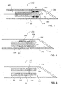
Figure 1 , which is a schematic illustration of a system, generally referenced 100, for navigating a surgical needle toward a target organ of the body of a patient, constructed and operative according to an embodiment of the disclosed technique.System 100 includes a medical positioning system (MPS) 102, amagnetic field generator 104, asurgical needle 106, aremovable mandrel 108, anMPS sensor unit 110, adisplay 112, and animage source 114.MPS 102 includes aprocessor 116, and an analog to digital converter (ADC) 118.MPS sensor unit 110 includes an MPS housing (not shown) and an MPS sensor (not shown). The MPS housing can be in form of an adhesive applied overMPS sensor unit 110, plastic tube, elastomeric tube overMPS sensor unit 110 by applying heat, and the like. The MPS sensor is located within the MPS housing. The MPS housing is in the form of a cylinder.Processor 116 is coupled withelectromagnetic field generator 104,display 112,image source 114, and withADC 118. - The MPS sensor is in the form of an electromagnetic coil (i.e., a wound wire), which produces an electrical output in response to an electromagnetic field. The MPS housing is made of a metal, such as stainless steel, and the like.
Removable mandrel 108 is made of a metal, such as stainless steel, plastic, ceramic, and the like.Removable mandrel 108 is in the form of a tube having abore 120.MPS sensor unit 110 is firmly coupled with the tip ofremovable mandrel 108 by methods known in the art, such as welding, brazing, employing an adhesive, pressure fit (e.g.,MPS sensor unit 110 having a conical shape), and the like. The MPS sensor is coupled withADC 118 bywires bore 120.Image source 114 is in the form of an imager such as computer tomography (CT), magnetic resonance imager (MRI), positron emission tomography (PET), single photon emission computer tomography (SPECT), ultrasound image detector, infrared image detector, X-ray imager (e.g., C-arm), optical coherence tomography (OCT), and the like.Image source 114 provides a real-time video image (not shown) of an organ (not shown) of the body (not shown) of a patient (not shown), which is acquired during medical operation on the patient. Alternatively,image source 114 is in the form of a database, which includes an image of the organ, which is acquired prior to the medical operation on the patient. Further alternatively,image source 114 includes a still image of the organ. -
Image source 114 can produce a two-dimensional image of the target organ. Alternatively,image source 114 can produce a three-dimensional image of the target organ. Further alternatively,image source 114 can produce a right view and a left view of the target organ, thereby enabling a user to perceive a stereoscopic sensation of the image, by viewing the image on display 112 (e.g., by employing a stereoscopic pair of glasses). - An outer diameter of
removable mandrel 108 is less than an inner diameter of alumen 126 ofsurgical needle 106, to enable movement ofremovable mandrel 108 withinlumen 126, in directions designated byarrows removable mandrel 108 and ofMPS sensor unit 110 is of such value thatMPS sensor unit 110 andremovable mandrel 108 can be moved in unison, indirections MPS sensor unit 110 physically separates adistal portion 132 oflumen 126 from aproximal portion 134 oflumen 126. In this manner,MPS sensor unit 110 seals against aninner wall 136 oflumen 126, and thereby, fluids and solid materials which are located atdistal portion 132, can not reachproximal portion 134. - The user can employ
surgical needle 106 to withdraw a sample of a bodily fluid (e.g., amniotic fluid) from a target organ of the patient (e.g., the uterus cavity of the patient). Alternatively, the user can employsurgical needle 106 to inject a therapeutic substance (e.g., anticarcinogen, anticoagulant), into the target organ. In casesurgical needle 106 is employed for collecting a fluid sample,removable mandrel 108 is employed for preventing contamination of the fluid sample. In casesurgical needle 106 is employed for injecting a therapeutic substance into the target organ,removable mandrel 108 is employed for flushing out chemical compounds fromsurgical needle 106. - When the user pierces the skin of the patient with
surgical needle 106, in order to reach a selected region of the target organ, which includes the desired bodily fluid,surgical needle 106 passes through various tissues and fluids, which are located in the vicinity of the target organ. In order to perform a reliable assay of the bodily fluid of the target organ, the sample of the bodily fluid should be substantially pure and substantially free of undesired bodily substances (e.g., tissues and fluids) which are located in the vicinity of the target organ. - Before piercing the skin of the patient, the user moves
removable mandrel 108 indirection 128 intolumen 126 ofsurgical needle 106, such thatMPS sensor unit 110 is located atdistal portion 132. In this manner,MPS sensor unit 110 prevents the undesired substances to reachproximal portion 134 fromdistal portion 132, and blocks entrance of the undesired substances toproximal portion 134. - The MPS sensor produces an analog electrical output in response to the electromagnetic filed which electromagnetic filed
generator 104 generates.ADC 118 converts the analog electrical output to a digital format, and provides this digital output toprocessor 116.Processor 116 determines the position of the MPS sensor, and thus the tip ofremovable mandrel 108 in a three-dimensional coordinate system, according to this digital output.Processor 116 produces an indication of the position of the tip ofsurgical needle 106 according to the position of the MPS sensor, for the user to navigatesurgical needle 106 toward the target organ. This indication can be for example, visual, aural, tactile, and the like. - In case of a visual indication,
display 112 displays the visual indication. In case the indication is aural, or tactile, the system includes a user interface (not shown), coupled with the processor, to present this indication to the user. -
Processor 116 can superimpose a representation (not shown) of the position of the tip ofremovable mandrel 108, on an image of the target organ whichimage source 114 provides.Processor 116, then directsdisplay 112 to display a superposition of the representation of the position of the tip ofremovable mandrel 108 on the image of the target organ. In this manner, the user can view a trajectory of the tip ofremovable mandrel 108, anddistal portion 132, as the user advancessurgical needle 106 in the body of the patient, toward the target organ. With the aid of this view, the user can maneuversurgical needle 106 within the body of the patient, in such a manner that the surrounding tissue is minimally severed, and furthermore, thedistal portion 132 reaches directly the selected region of the target organ. - The user can employ
surgical needle 106 to withdraw a sample of a bodily fluid from the target organ. In this case, whensystem 100 informs the user thatdistal portion 132 is located at the selected region of the target organ, the user can pull outremovable mandrel 108 fromlumen 126 ofsurgical needle 106, and collect the sample of the bodily fluid in a container (e.g., a vial), by employing a sucking mechanism (e.g., a mechanical pump, an electric pump). It is noted thatMPS sensor unit 110 which is located at the tip ofremovable mandrel 108, blocks entrance of undesired bodily substances toproximal portion 134, thereby preventing contamination of the sample of the bodily fluid of the target organ. - Alternatively, the user can employ the surgical needle to inject a therapeutic substance into the target organ. In this case, when the system informs the user that distal portion of the surgical needle is located at the selected region of the target organ, the user can pull out a removable mandrel which is made of a solid rod, from the lumen of the surgical needle, and then inject the therapeutic substance into the target organ.
- It is further noted that
surgical needle 106 can be a disposable surgical needle in order to prevent transfer of contagious diseases among different patients. However,removable mandrel 108 together withsensor unit 110 can be used for performing medical operations on different patients. In this case, the probability of transfer of a virus or a bacterium among patients is reduced, for example, by placing a disposable barrier over the removable mandrel (e.g., a polymer sheet such as Latex), by sterilizing the removable mandrel prior to the medical operation, and the like. - Reference is now made to
Figure 2 , which is a schematic illustration of a system, generally referenced 160, for navigating a surgical needle toward a target organ of the body of a patient, constructed and operative according to another embodiment of the disclosed technique.System 160 includes anMPS 162, areceiver 164, anelectromagnetic field generator 166, atransmitter 168, aremovable mandrel 170, anMPS sensor unit 172, asurgical needle 174, adisplay 176 and animage source 178.MPS 162 includes aprocessor 180 and anADC 182.MPS 162,electromagnetic field generator 166,surgical needle 174,display 176 andimage source 178, are similar toMPS 102,electromagnetic field generator 104,surgical needle 106,display 112, andimage source 114, respectively, as described herein above in connection withFigure 1 . -
MPS sensor unit 172 includes an MPS sensor (not shown) and an MPS housing (not shown), similar to the MPS sensor and the MPS housing ofsensor unit 110, as described herein above in connection withFigure 1 .Removable mandrel 170 is in the form of a solid rod. Alternatively, the removable mandrel is in the form of a tube, similar toremovable mandrel 108, as described herein above in connection withFigure 1 . -
Processor 180 is coupled withelectromagnetic field generator 166,display 176,image source 178, and withADC 182.Receiver 164 is coupled withADC 182.MPS sensor unit 172 is coupled with the tip ofremovable mandrel 170 in a similar manner of coupling ofMPS sensor unit 110 withremovable mandrel 108, as described herein above in connection withFigure 1 .Transmitter 168 is coupled withreceiver 164 by a wireless link, such as Bluetooth, WiFi, Zigbee, IEEE 802 series connections, and the like. -
Transmitter 168 is physically coupled withremovable mandrel 170 and withMPS sensor unit 172, and electrically coupled with the MPS sensor.Transmitter 168 is located at the tip ofremovable mandrel 170. In this case,removable mandrel 170 is in the form of a solid rod. Alternatively,transmitter 168 is located at a proximal end of the removable mandrel, in which case the transmitter is coupled with the MPS sensor by a pair of wires which pass through a bore of the removable mandrel. Further alternatively,transmitter 168 can be integrated withMPS sensor unit 172.System 160 operates similar tosystem 100, except that the MPS sensor is coupled withMPS 162 by a wireless link. - Reference is now made to
Figure 3 , which is a schematic illustration of a device, generally referenced 210, for either withdrawing a sample of a bodily fluid from a target organ of the body of a patient, or injecting a therapeutic substance into the target organ, constructed and operative according to a further embodiment of the disclosed technique.Device 210 includes asurgical needle 212, aremovable mandrel 214 and anMPS sensor 216.Removable mandrel 214 is in the form of a tubing, having abore 218.MPS sensor 216 is in the form of a wire, which is wound around anouter surface 220 ofremovable mandrel 214, at the tip ofremovable mandrel 214.MPS sensor 216 is coupled with an MPS (not shown) similar to MPS 102 (Figure 1 ), with a pair of wires (not shown) passing throughbore 218, as described herein above. - Alternatively,
device 210 can include a transmitter (not shown), similar to transmitter 168 (Figure 2 ) as described herein above. This transmitter is coupled with the MPS sensor, with the removable mandrel, and with a receiver (not shown), similar to the coupling as described herein above in connection withFigure 2 . - Each of an outer diameter of
removable mandrel 214, and a wire diameter ofMPS sensor 216 is of such value thatMPS sensor 216 andouter surface 220 ofremovable mandrel 214 seal against aninside wall 222 of alumen 224 ofsurgical needle 212. In this manner, the tip ofremovable mandrel 214 blocks entrance of undesired bodily substances from adistal portion 226 oflumen 224 to aproximal portion 228 oflumen 224. Hence,device 210 enables withdrawal of a substantially uncontaminated sample of a bodily fluid from a target organ (not shown) of the body (not shown) of a patient (not shown). - In the example set forth in
Figure 3 ,removable mandrel 214 is in the form of a tubing. Applicant has found out that if the diameter ofbore 218 is small enough, thenremovable mandrel 214 can block the entrance of undesired bodily substances fromdistal portion 226 oflumen 224 toproximal portion 228 oflumen 224. It is noted that this blocking action depends on the relation between the diameter ofbore 218 and the viscosity of the undesired bodily substances (i.e., if the diameter ofbore 218 is sufficiently small, or the viscosity of the undesired bodily substance is sufficiently large, then the undesired bodily substance can not flow within bore 218). However, the removable mandrel can be made of a solid rod, in whichcase MPS sensor 216 sends an output thereof to the MPS, via the transmitter. - Reference is now made to
Figure 4 , which is a schematic illustration of a device generally referenced 250, either for withdrawing a sample of a bodily fluid from a target organ of the body of a patient, or injecting a therapeutic substance into the target organ, constructed and operative according to another embodiment of the disclosed technique.Device 250 includes asurgical needle 252, anMPS sensor unit 254, aradiopaque marker 256 and aremovable mandrel 258.MPS sensor unit 254 includes an MPS sensor (not shown) and an MPS housing (not shown). The MPS sensor unit is located within the MPS housing.MPS sensor unit 254 andradiopaque marker 256 are located at adistal portion 266 ofremovable mandrel 258. - The MPS housing includes a housing bore there within (i.e., the MPS housing is in the form of a tube). An inner diameter of the housing bore is substantially equal to an outer diameter of
removable mandrel 258. An inside wall (not shown) of the housing bore is coupled with anouter surface 260 ofremovable mandrel 258, by fastening methods known in the art, such as welding, brazing, by employing an adhesive, and the like.Radiopaque marker 256 is in the form of a metallic foil, which is visible in an X-ray image thereof (i.e.,radiopaque marker 256 fluoresces under X-ray). Each of a housing outside diameter of the MPS housing, an inside wall diameter of aninside wall 262 of alumen 264 ofsurgical needle 252, and a marker outer diameter ofradiopaque marker 256 is of such value thatMPS sensor unit 254 seals againstinside wall 262, while an assembly ofremovable mandrel 258,MPS sensor unit 254 andradiopaque marker 256 move withinlumen 264. - The MPS sensor is coupled with an MPS (not shown). A processor (not shown) superimposes a representation of a position of the tip of
removable mandrel 258 on a real-time image (e.g., an X-ray image - not shown) of a target organ (not shown) of the body (not shown) of a patient (not shown). The processor directs a display (not shown) to display this X-ray image, along with a real-time image ofradiopaque marker 256. - In the example set forth in
Figure 4 ,removable mandrel 258 is in the form of a tubing. Applicant has found out that if the diameter of a mandrel bore ofremovable mandrel 258 is small enough, thenremovable mandrel 258 can block the entrance of undesired bodily substances from a distal portion oflumen 264 to a proximal portion oflumen 264. However, the removable mandrel can be made of a solid rod, in which case the MPS sensor sends an output thereof to the MPS, via a transmitter (not shown), similar to transmitter 168 (Figure 2 ) as described herein above. - Reference is now made to
Figure 5 , which is a schematic illustration of a device generally referenced 290, either for withdrawing a sample of a bodily fluid from a target organ of the body of a patient, or injecting a therapeutic substance into the target organ, constructed and operative according to a further embodiment of the disclosed technique.Device 290 includes asurgical needle 292, anMPS sensor unit 294 and aremovable mandrel 296.MPS sensor unit 294 includes an MPS sensor (not shown) and an MPS housing (not shown). The MPS sensor is located within the MPS housing. - A mandrel
outer surface 298 ofremovable mandrel 296 includes an undercut 300.MPS sensor unit 294 is similar to MPS sensor unit 254 (Figure 4 ) as described herein above.MPS sensor unit 294 fits inside undercut 300. Each of a housing outer diameter of the MPS housing, and a mandrel outer diameter ofremovable mandrel 296 is of such value that mandrelouter surface 298 and a housingouter surface 302 of the MPS housing seal against aninside wall 304 of alumen 306 ofsurgical needle 292, whileremovable mandrel 296 moves withinlumen 306. - In the example set forth in
Figure 5 ,removable mandrel 296 is in the form of a tubing. Applicant has found out that if the diameter of a mandrel bore ofremovable mandrel 296 is small enough, thenremovable mandrel 296 can block the entrance of undesired bodily substances from a distal portion oflumen 306 to a proximal portion oflumen 306. However, the removable mandrel can be made of a solid rod, in which case the MPS sensor sends an output thereof to the MPS, via a transmitter (not shown), similar to transmitter 168 (Figure 2 ) as described herein above. - Reference is now made to
Figure 6 , which is a schematic illustration of a method for operating the system ofFigure 1 . Inprocedure 330, an MPS sensor located at the tip of a removable mandrel of a surgical needle, is coupled with an MPS, the removable mandrel being located within the surgical needle. With reference toFigure 1 , the MPS sensor ofMPS sensor unit 110 is coupled withMPS 102, bywires MPS sensor unit 110 is located at the tip ofremovable mandrel 108. - In
procedure 332, an electromagnetic field is generated by an electromagnetic field generator. With reference toFigure 1 ,electromagnetic field generator 104 generates an electromagnetic field. - In
procedure 334, an output is produced by the MPS sensor according to the electromagnetic field. With reference toFigure 1 , the MPS sensor ofMPS sensor unit 110 produces an analog electrical output, in response to the electromagnetic field generated byelectromagnetic field generator 104. - In
procedure 336, the coordinates respective of the position of the tip of the removable mandrel is determined, in a coordinate system respective of the MPS, according to the output of the MPS sensor. With reference toFigure 1 ,ADC 118 converts the analog electrical output produced by the MPS sensor inprocedure 334, to digital format.Processor 116 determines the position of the MPS sensor, and thus the position of the tip ofremovable mandrel 108, in an MPS coordinate system respective ofMPS 102, according to the electrical output of the MPS sensor, in digital format. - In
procedure 338, an indication of the position of the tip of the removable mandrel is produced, to enable navigation of the surgical needle toward the target organ. With reference toFigure 1 ,processor 116 superimposes a representation of the position of the tip ofremovable mandrel 108, in an MPS coordinate system ofMPS 102, on an image of the target organ, and directsdisplay 112 to display this superimposed image. By viewing the superimposed image ondisplay 112, the physical staff can verify the position of the tip ofremovable mandrel 108, and thus the tip ofsurgical needle 106 relative to the selected region within the target organ. Once the physical staff ensures that the tip ofsurgical needle 106 is located at the desired position within the target organ, she can withdraw a sample of the bodily fluid from the target organ, after removingremovable mandrel 108 fromsurgical needle 106. - It will be appreciated by persons skilled in the art that the disclosed technique is not limited to what has been particularly shown and described hereinabove. Rather the scope of the disclosed technique is defined only by the claims, which follow.
Claims (19)
- Surgical needle device comprising:a surgical needle (106, 174, 212, 252, 292) having a lumen (126, 224, 264, 306), wherein the lumen (126, 224, 264, 306) has an inner wall (136, 222, 262, 304),a removable mandrel (108, 170, 214, 258, 296) suitable for being located within said surgical needle (110, 172, 216, 254, 294), said removable mandrel (108, 170, 214, 258, 296) to be moved in and moved out of said surgical needle (106, 174, 212, 252, 292); anda medical positioning system (MPS) sensor (110, 172, 216, 254, 294) located at the tip of said removable mandrel (108, 170, 214, 258, 296),said MPS sensor (110, 172, 216, 254, 294) to be coupled with an MPS (102, 162), said MPS (102, 162) to be coupled with an electromagnetic field generator (104, 166), said electromagnetic field generator (104, 166) generating an electromagnetic field, said MPS sensor (110, 172, 216, 254, 294) producing an output according to said electromagnetic field, said MPS (102, 162) determining the position of said tip of said removable mandrel (108, 170, 214, 258, 296) in a coordinate system respective of said MPS (102, 162), according to said output of said MPS sensor (110, 172, 216, 254, 294), said MPS (102, 162) producing an indication respective of said position, to enable navigation of said surgical needle (106, 174, 212, 252, 292) toward a target organ,characterized in thatsaid MPS sensor (110, 172, 216, 254, 294) is firmly coupled with the tip of said removable mandrel (108, 170, 214, 258, 296) such that said MPS sensor (110, 172, 216, 254, 294) seals against said inner wall (136, 222, 262, 304) of said lumen (126, 224, 264, 306), whereby the entrance of undesired bodily substances into the surgical needle (106, 174, 212, 252, 292) is blocked, while said surgical needle (106, 174, 212, 252, 292) is being advanced toward said target organ.
- The device according to claim 1, wherein said surgical needle (106, 174, 212, 252, 292) is suitable for withdrawing a sample of a bodily fluid from said target organ.
- The device according to claim 1 or 2, wherein said surgical needle (106, 174, 212, 252, 292) is suitable for injecting a therapeutic substance into said target organ.
- The device according to any one of the preceding claims, wherein said surgical needle is disposable.
- The device according to any one of the preceding claims, wherein said MPS sensor is located within an MPS housing, said MPS housing being in the form of a cylinder,
wherein said MPS housing is firmly coupled with said tip of said removable mandrel (108, 170, 214, 258, 296). - The device according to any one of claims 1 to 4, wherein said MPS sensor is located within an MPS housing, said MPS housing being in the form of a tube, and
wherein said MPS housing is firmly coupled with an outer periphery of said removable mandrel (108, 170, 214, 258, 296), at a distal end of said removable mandrel (108, 170, 214, 258, 296). - The device according to claim 6, wherein an inner diameter of said MPS housing is substantially equal to an outer diameter of said removable mandrel (108, 170, 214, 258, 296).
- The device according to claim 6, wherein a housing outer diameter (302) of said MPS housing is substantially equal to a mandrel outer diameter of said removable mandrel (108, 170, 214, 258, 296),
wherein said removable mandrel (108, 170, 214, 258, 296) includes an undercut (300) at a distal portion thereof, and
wherein said MPS housing is located within said undercut (300). - The device according to any one of claims 1 to 4, wherein said MPS sensor (110, 172, 216, 254, 294) is located within an MPS housing, said MPS housing being in the form of an adhesive, covering said MPS sensor (110, 172, 216, 254, 294).
- The device according to any one of the preceding claims, wherein said removable mandrel (108, 170, 214, 258, 296) is in the form of a solid rod.
- The device according to any one of claims 1 to 9, wherein said removable mandrel (108, 170, 214, 258, 296) is in the form of a tube.
- The device according to any one of claims 1 to 4, wherein said MPS sensor is in the form of an electrically conductive coil wound around an outer surface of said removable mandrel (108, 170, 214, 258, 296).
- The device according to any one of the preceding claims, further comprising a disposable barrier placed over said removable mandrel (108, 170, 214, 258, 296), said disposable barrier reducing the probability of transfer of a virus or a bacterium from said patient to another patient.
- The device according to any one of the preceding claims, wherein said removable mandrel (108, 170, 214, 258, 296) blocks entrance of undesired bodily substances of said body of said patient, into said surgical needle (106, 174, 212, 252, 292), while said surgical needle (106, 174, 212, 252, 292) is being advanced toward said target organ.
- System (100, 160) for navigating a surgical needle (106, 174, 212, 252, 292) toward a target organ of the body of a patient, the system (100, 160) comprising:a surgical needle device according to any one of the preceding claims;an electromagnetic field generator (104, 166) for generating an electromagnetic field; andan MPS (102, 162) coupled with said MPS sensor (110, 172, 216, 254, 294) and with said electromagnetic field generator (104, 166), said MPS sensor (110, 172, 216, 254, 294) producing an output according to said electromagnetic field, said MPS (102, 162) determining the position of said tip of said removable mandrel (108, 170, 214, 258, 296) in a coordinate system respective of said MPS (102, 162), according to said output of said MPS sensor (110, 172, 216, 254, 294), said MPS (102, 162) producing an indication respective of said position, to enable navigation of said surgical needle (106, 174, 212, 252, 292) toward said target organ.
- The system (100, 160) according to claim 15, further comprising:a processor (116, 180) coupled with said MPS sensor (110, 172, 216, 254, 294);an image source (114) coupled with said processor (116, 180), said image source (114) including an organ image of said target organ; anda display (112) coupled with said processor (116, 180),wherein said processor (116, 180) determines said position of said MPS sensor (110, 172, 216, 254, 296), according to said output,wherein said processor (116, 180) produces a superposition of a representation of said position on said organ image, andwherein said display (112) displays said superposition.
- The system (100, 160) according to claim 16, further comprising a radiopaque marker (256) located at said tip of said removable mandrel (108, 170, 214, 258, 296), wherein said display (112) displays a marker image of said radiopaque marker (256) against an organ image of said target organ.
- The system (100, 160) according to any one of claims 15 to 17, wherein said MPS sensor (110, 172, 216, 254, 294) is coupled with said MPS (102, 162), via an electric conductor.
- The system (100, 160) according to any one of claims 15 to 17, wherein said indication is selected from the list consisting of:visual, aural and tactile.
Applications Claiming Priority (1)
| Application Number | Priority Date | Filing Date | Title |
|---|---|---|---|
| US86111806P | 2006-11-27 | 2006-11-27 |
Publications (2)
| Publication Number | Publication Date |
|---|---|
| EP1925262A1 EP1925262A1 (en) | 2008-05-28 |
| EP1925262B1 true EP1925262B1 (en) | 2015-03-18 |
Family
ID=39204026
Family Applications (1)
| Application Number | Title | Priority Date | Filing Date |
|---|---|---|---|
| EP07121648.5A Not-in-force EP1925262B1 (en) | 2006-11-27 | 2007-11-27 | System for navigating a surgical needle toward an organ of the body of a patient |
Country Status (5)
| Country | Link |
|---|---|
| US (1) | US20080132911A1 (en) |
| EP (1) | EP1925262B1 (en) |
| JP (1) | JP5235389B2 (en) |
| CA (1) | CA2612433C (en) |
| IL (1) | IL187667A (en) |
Families Citing this family (56)
| Publication number | Priority date | Publication date | Assignee | Title |
|---|---|---|---|---|
| US7998062B2 (en) | 2004-03-29 | 2011-08-16 | Superdimension, Ltd. | Endoscope structures and techniques for navigating to a target in branched structure |
| EP2316328B1 (en) * | 2003-09-15 | 2012-05-09 | Super Dimension Ltd. | Wrap-around holding device for use with bronchoscopes |
| DE602004022432D1 (en) | 2003-09-15 | 2009-09-17 | Super Dimension Ltd | SYSTEM FROM ACCESSORIES FOR USE WITH BRONCHOSCOPES |
| US8764725B2 (en) | 2004-02-09 | 2014-07-01 | Covidien Lp | Directional anchoring mechanism, method and applications thereof |
| EP2086399B1 (en) | 2006-11-10 | 2017-08-09 | Covidien LP | Adaptive navigation technique for navigating a catheter through a body channel or cavity |
| US20080167639A1 (en) * | 2007-01-08 | 2008-07-10 | Superdimension Ltd. | Methods for localized intra-body treatment of tissue |
| WO2009074872A2 (en) * | 2007-07-09 | 2009-06-18 | Superdimension, Ltd. | Patent breathing modeling |
| US8905920B2 (en) | 2007-09-27 | 2014-12-09 | Covidien Lp | Bronchoscope adapter and method |
| EP2249737B1 (en) * | 2008-03-03 | 2020-07-01 | Koninklijke Philips N.V. | Biopsy guidance by electromagnetic tracking and photonic needle |
| US9575140B2 (en) | 2008-04-03 | 2017-02-21 | Covidien Lp | Magnetic interference detection system and method |
| US8218846B2 (en) * | 2008-05-15 | 2012-07-10 | Superdimension, Ltd. | Automatic pathway and waypoint generation and navigation method |
| US8473032B2 (en) | 2008-06-03 | 2013-06-25 | Superdimension, Ltd. | Feature-based registration method |
| US8218847B2 (en) | 2008-06-06 | 2012-07-10 | Superdimension, Ltd. | Hybrid registration method |
| US8932207B2 (en) | 2008-07-10 | 2015-01-13 | Covidien Lp | Integrated multi-functional endoscopic tool |
| RU2519300C2 (en) * | 2008-10-31 | 2014-06-10 | Конинклейке Филипс Электроникс, Н.В. | Electromagnetic tracking method and system in medical procedure |
| US8611984B2 (en) | 2009-04-08 | 2013-12-17 | Covidien Lp | Locatable catheter |
| US9895135B2 (en) * | 2009-05-20 | 2018-02-20 | Analogic Canada Corporation | Freehand ultrasound imaging systems and methods providing position quality feedback |
| US10039527B2 (en) | 2009-05-20 | 2018-08-07 | Analogic Canada Corporation | Ultrasound systems incorporating spatial position sensors and associated methods |
| US8319687B2 (en) * | 2009-12-09 | 2012-11-27 | Trimble Navigation Limited | System for determining position in a work space |
| US9486162B2 (en) | 2010-01-08 | 2016-11-08 | Ultrasonix Medical Corporation | Spatial needle guidance system and associated methods |
| JP5650248B2 (en) | 2010-02-01 | 2015-01-07 | コビディエン エルピー | Region expansion algorithm |
| US9820695B2 (en) | 2010-03-29 | 2017-11-21 | St. Jude Medical International Holding S.àr.l. | Method for detecting contact with the wall of a region of interest |
| WO2011159834A1 (en) | 2010-06-15 | 2011-12-22 | Superdimension, Ltd. | Locatable expandable working channel and method |
| US8971993B2 (en) | 2010-11-19 | 2015-03-03 | Mediguide Ltd. | Systems and methods for navigating a surgical device |
| US9439653B2 (en) | 2011-12-07 | 2016-09-13 | Traumatek Solutions B.V. | Devices and methods for endovascular access and therapy |
| US10118020B2 (en) | 2011-12-07 | 2018-11-06 | Traumatek Solutions B.V. | Devices and methods for endovascular access and therapy |
| US9295449B2 (en) | 2012-01-23 | 2016-03-29 | Ultrasonix Medical Corporation | Landmarks for ultrasound imaging |
| US8556883B2 (en) * | 2012-02-27 | 2013-10-15 | Rafic Saleh | Medical surgical navigation sensor mounting system |
| WO2014018611A1 (en) * | 2012-07-24 | 2014-01-30 | Montefiore Medical Center | Method for epicardial pacing or cardiac tissue ablation |
| US20140051985A1 (en) * | 2012-08-17 | 2014-02-20 | Tailin Fan | Percutaneous nephrolithotomy target finding system |
| US10952593B2 (en) | 2014-06-10 | 2021-03-23 | Covidien Lp | Bronchoscope adapter |
| CN104473677B (en) * | 2014-12-23 | 2016-08-17 | 东南大学 | A kind of puncture needle of band magnetic grid scale |
| US10426555B2 (en) | 2015-06-03 | 2019-10-01 | Covidien Lp | Medical instrument with sensor for use in a system and method for electromagnetic navigation |
| EP3313289B1 (en) | 2015-06-23 | 2021-03-17 | Traumatek Solutions B.V. | Vessel cannulation device |
| US10524695B2 (en) * | 2015-12-22 | 2020-01-07 | Biosense Webster (Israel) Ltd. | Registration between coordinate systems for visualizing a tool |
| US10244963B2 (en) * | 2015-12-22 | 2019-04-02 | Biosense Webster (Israel) Ltd. | Ascertaining a position and orientation for visualizing a tool |
| US10327667B2 (en) * | 2016-05-13 | 2019-06-25 | Becton, Dickinson And Company | Electro-magnetic needle catheter insertion system |
| US10478254B2 (en) | 2016-05-16 | 2019-11-19 | Covidien Lp | System and method to access lung tissue |
| US11826522B2 (en) | 2016-06-01 | 2023-11-28 | Becton, Dickinson And Company | Medical devices, systems and methods utilizing permanent magnet and magnetizable feature |
| US20170347914A1 (en) | 2016-06-01 | 2017-12-07 | Becton, Dickinson And Company | Invasive Medical Devices Including Magnetic Region And Systems And Methods |
| US11413429B2 (en) | 2016-06-01 | 2022-08-16 | Becton, Dickinson And Company | Medical devices, systems and methods utilizing permanent magnet and magnetizable feature |
| US10583269B2 (en) | 2016-06-01 | 2020-03-10 | Becton, Dickinson And Company | Magnetized catheters, devices, uses and methods of using magnetized catheters |
| US10032552B2 (en) | 2016-08-30 | 2018-07-24 | Becton, Dickinson And Company | Cover for tissue penetrating device with integrated magnets and magnetic shielding |
| US10418705B2 (en) | 2016-10-28 | 2019-09-17 | Covidien Lp | Electromagnetic navigation antenna assembly and electromagnetic navigation system including the same |
| US10792106B2 (en) | 2016-10-28 | 2020-10-06 | Covidien Lp | System for calibrating an electromagnetic navigation system |
| US10517505B2 (en) | 2016-10-28 | 2019-12-31 | Covidien Lp | Systems, methods, and computer-readable media for optimizing an electromagnetic navigation system |
| US10446931B2 (en) | 2016-10-28 | 2019-10-15 | Covidien Lp | Electromagnetic navigation antenna assembly and electromagnetic navigation system including the same |
| US10615500B2 (en) | 2016-10-28 | 2020-04-07 | Covidien Lp | System and method for designing electromagnetic navigation antenna assemblies |
| US10722311B2 (en) | 2016-10-28 | 2020-07-28 | Covidien Lp | System and method for identifying a location and/or an orientation of an electromagnetic sensor based on a map |
| US10638952B2 (en) | 2016-10-28 | 2020-05-05 | Covidien Lp | Methods, systems, and computer-readable media for calibrating an electromagnetic navigation system |
| US10751126B2 (en) | 2016-10-28 | 2020-08-25 | Covidien Lp | System and method for generating a map for electromagnetic navigation |
| US11219489B2 (en) | 2017-10-31 | 2022-01-11 | Covidien Lp | Devices and systems for providing sensors in parallel with medical tools |
| US20210378516A1 (en) * | 2018-10-08 | 2021-12-09 | University Of Florida Research Foundation, Incorporated | Method and system for positioning invasive medical tools relative to 3d imagery |
| US12089902B2 (en) | 2019-07-30 | 2024-09-17 | Coviden Lp | Cone beam and 3D fluoroscope lung navigation |
| US20230404521A1 (en) * | 2022-06-17 | 2023-12-21 | Boston Scientific Scimed, Inc. | Medical device position sensing components |
| CN118948350B (en) * | 2024-10-16 | 2024-12-17 | 北京迈迪斯医疗技术有限公司 | Full-automatic biopsy needle based on electromagnetic positioning |
Family Cites Families (35)
| Publication number | Priority date | Publication date | Assignee | Title |
|---|---|---|---|---|
| US4431006A (en) * | 1982-01-07 | 1984-02-14 | Technicare Corporation | Passive ultrasound needle probe locator |
| US5005585A (en) * | 1989-04-24 | 1991-04-09 | Marshfield Clinic | Biopsy needle construction |
| US5086780A (en) * | 1990-05-21 | 1992-02-11 | Abbott Laboratories | Blood collection device |
| JP3506770B2 (en) * | 1994-04-21 | 2004-03-15 | オリンパス株式会社 | Endoscope position detection device |
| JP3772151B2 (en) * | 1994-04-21 | 2006-05-10 | オリンパス株式会社 | Insertion position detection device |
| ATE188108T1 (en) * | 1994-08-19 | 2000-01-15 | Biosense Inc | MEDICAL DIAGNOSIS, TREATMENT AND DISPLAY SYSTEM |
| US5697377A (en) * | 1995-11-22 | 1997-12-16 | Medtronic, Inc. | Catheter mapping system and method |
| US20030069522A1 (en) * | 1995-12-07 | 2003-04-10 | Jacobsen Stephen J. | Slotted medical device |
| US5711299A (en) * | 1996-01-26 | 1998-01-27 | Manwaring; Kim H. | Surgical guidance method and system for approaching a target within a body |
| SE9600334D0 (en) * | 1996-01-30 | 1996-01-30 | Radi Medical Systems | Combined flow, pressure and temperature sensor |
| IL119262A0 (en) | 1996-02-15 | 1996-12-05 | Biosense Israel Ltd | Locatable biopsy needle |
| US5882304A (en) | 1997-10-27 | 1999-03-16 | Picker Nordstar Corporation | Method and apparatus for determining probe location |
| US6073043A (en) | 1997-12-22 | 2000-06-06 | Cormedica Corporation | Measuring position and orientation using magnetic fields |
| US6235001B1 (en) * | 1998-05-18 | 2001-05-22 | O'holloran Brian | Surgical needle with hand-actuable lock mechanism |
| US7174201B2 (en) * | 1999-03-11 | 2007-02-06 | Biosense, Inc. | Position sensing system with integral location pad and position display |
| US8442618B2 (en) * | 1999-05-18 | 2013-05-14 | Mediguide Ltd. | Method and system for delivering a medical device to a selected position within a lumen |
| US7778688B2 (en) * | 1999-05-18 | 2010-08-17 | MediGuide, Ltd. | System and method for delivering a stent to a selected position within a lumen |
| US7809421B1 (en) * | 2000-07-20 | 2010-10-05 | Biosense, Inc. | Medical system calibration with static metal compensation |
| US6785571B2 (en) * | 2001-03-30 | 2004-08-31 | Neil David Glossop | Device and method for registering a position sensor in an anatomical body |
| WO2002085442A1 (en) * | 2001-04-19 | 2002-10-31 | Radi Medical Systems Ab | Combined pressure-volume sensor and guide wire assembly |
| US7697972B2 (en) * | 2002-11-19 | 2010-04-13 | Medtronic Navigation, Inc. | Navigation system for cardiac therapies |
| US7241283B2 (en) * | 2003-04-25 | 2007-07-10 | Ad-Tech Medical Instrument Corp. | Method for intracranial catheter treatment of brain tissue |
| US8333734B2 (en) * | 2003-07-03 | 2012-12-18 | Walter A. Zohmann | Fenestrated peripheral nerve block needle and method for using the same |
| JP2005157509A (en) * | 2003-11-21 | 2005-06-16 | Hitachi Ltd | Communication terminal |
| US7462175B2 (en) * | 2004-04-21 | 2008-12-09 | Acclarent, Inc. | Devices, systems and methods for treating disorders of the ear, nose and throat |
| US20070208252A1 (en) * | 2004-04-21 | 2007-09-06 | Acclarent, Inc. | Systems and methods for performing image guided procedures within the ear, nose, throat and paranasal sinuses |
| US7708751B2 (en) * | 2004-05-21 | 2010-05-04 | Ethicon Endo-Surgery, Inc. | MRI biopsy device |
| ATE444712T1 (en) * | 2004-05-21 | 2009-10-15 | Ethicon Endo Surgery Inc | MRI BIOPSY DEVICE WITH A DISPLAYABLE PENETRATION PART |
| US7632265B2 (en) * | 2004-05-28 | 2009-12-15 | St. Jude Medical, Atrial Fibrillation Division, Inc. | Radio frequency ablation servo catheter and method |
| US7263894B2 (en) * | 2004-06-07 | 2007-09-04 | Radi Medical Systems Ab | Sensor and guide wire assembly |
| GB2423369A (en) * | 2005-02-22 | 2006-08-23 | Depuy Int Ltd | A position sensing probe for computer assisted surgery |
| EP1876985B1 (en) * | 2005-05-05 | 2016-08-31 | Boston Scientific Scimed, Inc. | System for graphically reconstructing pulmonary vein ostia with preshaped localization catheter |
| WO2006126194A1 (en) * | 2005-05-24 | 2006-11-30 | Stryker Gi Ltd. | Tracking of disposable components |
| US7331236B2 (en) * | 2006-03-21 | 2008-02-19 | Radi Medical Systems Ab | Pressure sensor |
| US7819844B2 (en) * | 2007-10-17 | 2010-10-26 | Gardia Medical Ltd. | Guidewire stop |
-
2007
- 2007-11-26 IL IL187667A patent/IL187667A/en active IP Right Grant
- 2007-11-27 JP JP2007305713A patent/JP5235389B2/en active Active
- 2007-11-27 CA CA2612433A patent/CA2612433C/en not_active Expired - Fee Related
- 2007-11-27 US US11/945,828 patent/US20080132911A1/en not_active Abandoned
- 2007-11-27 EP EP07121648.5A patent/EP1925262B1/en not_active Not-in-force
Also Published As
| Publication number | Publication date |
|---|---|
| IL187667A0 (en) | 2008-03-20 |
| EP1925262A1 (en) | 2008-05-28 |
| US20080132911A1 (en) | 2008-06-05 |
| JP2008253729A (en) | 2008-10-23 |
| IL187667A (en) | 2011-12-29 |
| CA2612433A1 (en) | 2008-05-27 |
| CA2612433C (en) | 2016-05-10 |
| JP5235389B2 (en) | 2013-07-10 |
Similar Documents
| Publication | Publication Date | Title |
|---|---|---|
| EP1925262B1 (en) | System for navigating a surgical needle toward an organ of the body of a patient | |
| JP7526973B2 (en) | Medical device with visual puncture device | |
| US9888970B2 (en) | Systems and methods for navigating a surgical device | |
| US11529070B2 (en) | System and methods for guiding a medical instrument | |
| US6580938B1 (en) | Image-guided thoracic therapy and apparatus therefor | |
| EP3087922B1 (en) | System for registration of images captured by an imaging system in a coordinate system of a medical device navigation system | |
| EP1838378B1 (en) | Apparatus for guiding an instrument to a target in the lung | |
| EP3294181B1 (en) | Adjustable length medical instrument assembly with localization elements for tracking medical instrument extension | |
| US8150495B2 (en) | Bodily sealants and methods and apparatus for image-guided delivery of same | |
| JP4993982B2 (en) | Catheter apparatus and treatment apparatus | |
| US8784800B2 (en) | Method of delivering cell therapy to a target site | |
| EP0910300A1 (en) | Medical procedures and apparatus using intrabody probes | |
| WO1997029682A1 (en) | Locatable biopsy needle | |
| AU741022B2 (en) | Image-guided thoracic therapy and apparatus therefor | |
| CN116650081A (en) | Coaxial puncture needle and puncture system based on electromagnetic navigation | |
| JP2003180680A (en) | Navigation system | |
| KR20160008181A (en) | Medical device and its construction | |
| US10695038B2 (en) | Devices, systems, and methods for obtaining a tissue sample | |
| CN107997830A (en) | Rigid ear nose larynx instrument | |
| EP3426178B1 (en) | A system for navigated punction, biopsy or ablation comprising a needle-like instrument and a removable sensor carrier |
Legal Events
| Date | Code | Title | Description |
|---|---|---|---|
| PUAI | Public reference made under article 153(3) epc to a published international application that has entered the european phase |
Free format text: ORIGINAL CODE: 0009012 |
|
| AK | Designated contracting states |
Kind code of ref document: A1 Designated state(s): AT BE BG CH CY CZ DE DK EE ES FI FR GB GR HU IE IS IT LI LT LU LV MC MT NL PL PT RO SE SI SK TR |
|
| AX | Request for extension of the european patent |
Extension state: AL BA HR MK RS |
|
| 17P | Request for examination filed |
Effective date: 20081119 |
|
| AKX | Designation fees paid |
Designated state(s): AT BE BG CH CY CZ DE DK EE ES FI FR GB GR HU IE IS IT LI LT LU LV MC MT NL PL PT RO SE SI SK TR |
|
| 17Q | First examination report despatched |
Effective date: 20090129 |
|
| GRAP | Despatch of communication of intention to grant a patent |
Free format text: ORIGINAL CODE: EPIDOSNIGR1 |
|
| RIC1 | Information provided on ipc code assigned before grant |
Ipc: A61B 17/34 20060101AFI20141028BHEP Ipc: A61B 19/00 20060101ALI20141028BHEP Ipc: A61B 10/02 20060101ALI20141028BHEP |
|
| INTG | Intention to grant announced |
Effective date: 20141117 |
|
| GRAS | Grant fee paid |
Free format text: ORIGINAL CODE: EPIDOSNIGR3 |
|
| GRAA | (expected) grant |
Free format text: ORIGINAL CODE: 0009210 |
|
| AK | Designated contracting states |
Kind code of ref document: B1 Designated state(s): AT BE BG CH CY CZ DE DK EE ES FI FR GB GR HU IE IS IT LI LT LU LV MC MT NL PL PT RO SE SI SK TR |
|
| REG | Reference to a national code |
Ref country code: GB Ref legal event code: FG4D |
|
| REG | Reference to a national code |
Ref country code: CH Ref legal event code: EP |
|
| REG | Reference to a national code |
Ref country code: IE Ref legal event code: FG4D |
|
| REG | Reference to a national code |
Ref country code: AT Ref legal event code: REF Ref document number: 716025 Country of ref document: AT Kind code of ref document: T Effective date: 20150415 |
|
| REG | Reference to a national code |
Ref country code: DE Ref legal event code: R096 Ref document number: 602007040655 Country of ref document: DE Effective date: 20150430 |
|
| REG | Reference to a national code |
Ref country code: NL Ref legal event code: VDEP Effective date: 20150318 |
|
| REG | Reference to a national code |
Ref country code: NL Ref legal event code: VDEP Effective date: 20150318 |
|
| PG25 | Lapsed in a contracting state [announced via postgrant information from national office to epo] |
Ref country code: SE Free format text: LAPSE BECAUSE OF FAILURE TO SUBMIT A TRANSLATION OF THE DESCRIPTION OR TO PAY THE FEE WITHIN THE PRESCRIBED TIME-LIMIT Effective date: 20150318 Ref country code: FI Free format text: LAPSE BECAUSE OF FAILURE TO SUBMIT A TRANSLATION OF THE DESCRIPTION OR TO PAY THE FEE WITHIN THE PRESCRIBED TIME-LIMIT Effective date: 20150318 Ref country code: LT Free format text: LAPSE BECAUSE OF FAILURE TO SUBMIT A TRANSLATION OF THE DESCRIPTION OR TO PAY THE FEE WITHIN THE PRESCRIBED TIME-LIMIT Effective date: 20150318 |
|
| REG | Reference to a national code |
Ref country code: AT Ref legal event code: MK05 Ref document number: 716025 Country of ref document: AT Kind code of ref document: T Effective date: 20150318 |
|
| REG | Reference to a national code |
Ref country code: LT Ref legal event code: MG4D |
|
| PG25 | Lapsed in a contracting state [announced via postgrant information from national office to epo] |
Ref country code: LV Free format text: LAPSE BECAUSE OF FAILURE TO SUBMIT A TRANSLATION OF THE DESCRIPTION OR TO PAY THE FEE WITHIN THE PRESCRIBED TIME-LIMIT Effective date: 20150318 Ref country code: GR Free format text: LAPSE BECAUSE OF FAILURE TO SUBMIT A TRANSLATION OF THE DESCRIPTION OR TO PAY THE FEE WITHIN THE PRESCRIBED TIME-LIMIT Effective date: 20150619 |
|
| PG25 | Lapsed in a contracting state [announced via postgrant information from national office to epo] |
Ref country code: NL Free format text: LAPSE BECAUSE OF FAILURE TO SUBMIT A TRANSLATION OF THE DESCRIPTION OR TO PAY THE FEE WITHIN THE PRESCRIBED TIME-LIMIT Effective date: 20150318 |
|
| PG25 | Lapsed in a contracting state [announced via postgrant information from national office to epo] |
Ref country code: RO Free format text: LAPSE BECAUSE OF FAILURE TO SUBMIT A TRANSLATION OF THE DESCRIPTION OR TO PAY THE FEE WITHIN THE PRESCRIBED TIME-LIMIT Effective date: 20150318 Ref country code: PT Free format text: LAPSE BECAUSE OF FAILURE TO SUBMIT A TRANSLATION OF THE DESCRIPTION OR TO PAY THE FEE WITHIN THE PRESCRIBED TIME-LIMIT Effective date: 20150720 Ref country code: EE Free format text: LAPSE BECAUSE OF FAILURE TO SUBMIT A TRANSLATION OF THE DESCRIPTION OR TO PAY THE FEE WITHIN THE PRESCRIBED TIME-LIMIT Effective date: 20150318 Ref country code: CZ Free format text: LAPSE BECAUSE OF FAILURE TO SUBMIT A TRANSLATION OF THE DESCRIPTION OR TO PAY THE FEE WITHIN THE PRESCRIBED TIME-LIMIT Effective date: 20150318 Ref country code: ES Free format text: LAPSE BECAUSE OF FAILURE TO SUBMIT A TRANSLATION OF THE DESCRIPTION OR TO PAY THE FEE WITHIN THE PRESCRIBED TIME-LIMIT Effective date: 20150318 Ref country code: SK Free format text: LAPSE BECAUSE OF FAILURE TO SUBMIT A TRANSLATION OF THE DESCRIPTION OR TO PAY THE FEE WITHIN THE PRESCRIBED TIME-LIMIT Effective date: 20150318 |
|
| REG | Reference to a national code |
Ref country code: FR Ref legal event code: PLFP Year of fee payment: 9 |
|
| PG25 | Lapsed in a contracting state [announced via postgrant information from national office to epo] |
Ref country code: PL Free format text: LAPSE BECAUSE OF FAILURE TO SUBMIT A TRANSLATION OF THE DESCRIPTION OR TO PAY THE FEE WITHIN THE PRESCRIBED TIME-LIMIT Effective date: 20150318 Ref country code: AT Free format text: LAPSE BECAUSE OF FAILURE TO SUBMIT A TRANSLATION OF THE DESCRIPTION OR TO PAY THE FEE WITHIN THE PRESCRIBED TIME-LIMIT Effective date: 20150318 Ref country code: IS Free format text: LAPSE BECAUSE OF FAILURE TO SUBMIT A TRANSLATION OF THE DESCRIPTION OR TO PAY THE FEE WITHIN THE PRESCRIBED TIME-LIMIT Effective date: 20150718 |
|
| REG | Reference to a national code |
Ref country code: DE Ref legal event code: R097 Ref document number: 602007040655 Country of ref document: DE |
|
| PLBE | No opposition filed within time limit |
Free format text: ORIGINAL CODE: 0009261 |
|
| STAA | Information on the status of an ep patent application or granted ep patent |
Free format text: STATUS: NO OPPOSITION FILED WITHIN TIME LIMIT |
|
| PG25 | Lapsed in a contracting state [announced via postgrant information from national office to epo] |
Ref country code: DK Free format text: LAPSE BECAUSE OF FAILURE TO SUBMIT A TRANSLATION OF THE DESCRIPTION OR TO PAY THE FEE WITHIN THE PRESCRIBED TIME-LIMIT Effective date: 20150318 |
|
| 26N | No opposition filed |
Effective date: 20151221 |
|
| PG25 | Lapsed in a contracting state [announced via postgrant information from national office to epo] |
Ref country code: SI Free format text: LAPSE BECAUSE OF FAILURE TO SUBMIT A TRANSLATION OF THE DESCRIPTION OR TO PAY THE FEE WITHIN THE PRESCRIBED TIME-LIMIT Effective date: 20150318 |
|
| PG25 | Lapsed in a contracting state [announced via postgrant information from national office to epo] |
Ref country code: MC Free format text: LAPSE BECAUSE OF FAILURE TO SUBMIT A TRANSLATION OF THE DESCRIPTION OR TO PAY THE FEE WITHIN THE PRESCRIBED TIME-LIMIT Effective date: 20150318 Ref country code: LU Free format text: LAPSE BECAUSE OF FAILURE TO SUBMIT A TRANSLATION OF THE DESCRIPTION OR TO PAY THE FEE WITHIN THE PRESCRIBED TIME-LIMIT Effective date: 20151127 |
|
| REG | Reference to a national code |
Ref country code: CH Ref legal event code: PL |
|
| PG25 | Lapsed in a contracting state [announced via postgrant information from national office to epo] |
Ref country code: CH Free format text: LAPSE BECAUSE OF NON-PAYMENT OF DUE FEES Effective date: 20151130 Ref country code: LI Free format text: LAPSE BECAUSE OF NON-PAYMENT OF DUE FEES Effective date: 20151130 |
|
| REG | Reference to a national code |
Ref country code: IE Ref legal event code: MM4A |
|
| PG25 | Lapsed in a contracting state [announced via postgrant information from national office to epo] |
Ref country code: BE Free format text: LAPSE BECAUSE OF FAILURE TO SUBMIT A TRANSLATION OF THE DESCRIPTION OR TO PAY THE FEE WITHIN THE PRESCRIBED TIME-LIMIT Effective date: 20150318 |
|
| PG25 | Lapsed in a contracting state [announced via postgrant information from national office to epo] |
Ref country code: IE Free format text: LAPSE BECAUSE OF NON-PAYMENT OF DUE FEES Effective date: 20151127 |
|
| REG | Reference to a national code |
Ref country code: FR Ref legal event code: PLFP Year of fee payment: 10 |
|
| PG25 | Lapsed in a contracting state [announced via postgrant information from national office to epo] |
Ref country code: BG Free format text: LAPSE BECAUSE OF FAILURE TO SUBMIT A TRANSLATION OF THE DESCRIPTION OR TO PAY THE FEE WITHIN THE PRESCRIBED TIME-LIMIT Effective date: 20150318 Ref country code: HU Free format text: LAPSE BECAUSE OF FAILURE TO SUBMIT A TRANSLATION OF THE DESCRIPTION OR TO PAY THE FEE WITHIN THE PRESCRIBED TIME-LIMIT; INVALID AB INITIO Effective date: 20071127 |
|
| PG25 | Lapsed in a contracting state [announced via postgrant information from national office to epo] |
Ref country code: CY Free format text: LAPSE BECAUSE OF FAILURE TO SUBMIT A TRANSLATION OF THE DESCRIPTION OR TO PAY THE FEE WITHIN THE PRESCRIBED TIME-LIMIT Effective date: 20150318 |
|
| PG25 | Lapsed in a contracting state [announced via postgrant information from national office to epo] |
Ref country code: MT Free format text: LAPSE BECAUSE OF FAILURE TO SUBMIT A TRANSLATION OF THE DESCRIPTION OR TO PAY THE FEE WITHIN THE PRESCRIBED TIME-LIMIT Effective date: 20150318 Ref country code: TR Free format text: LAPSE BECAUSE OF FAILURE TO SUBMIT A TRANSLATION OF THE DESCRIPTION OR TO PAY THE FEE WITHIN THE PRESCRIBED TIME-LIMIT Effective date: 20150318 |
|
| REG | Reference to a national code |
Ref country code: FR Ref legal event code: PLFP Year of fee payment: 11 |
|
| REG | Reference to a national code |
Ref country code: FR Ref legal event code: PLFP Year of fee payment: 12 |
|
| PGFP | Annual fee paid to national office [announced via postgrant information from national office to epo] |
Ref country code: DE Payment date: 20181015 Year of fee payment: 12 |
|
| PGFP | Annual fee paid to national office [announced via postgrant information from national office to epo] |
Ref country code: IT Payment date: 20181119 Year of fee payment: 12 Ref country code: GB Payment date: 20181025 Year of fee payment: 12 Ref country code: FR Payment date: 20181017 Year of fee payment: 12 |
|
| REG | Reference to a national code |
Ref country code: DE Ref legal event code: R082 Ref document number: 602007040655 Country of ref document: DE Representative=s name: KRAMER BARSKE SCHMIDTCHEN PATENTANWAELTE PARTG, DE Ref country code: DE Ref legal event code: R081 Ref document number: 602007040655 Country of ref document: DE Owner name: ST. JUDE MEDICAL INTERNATIONAL HOLDING S.A.R.L, LU Free format text: FORMER OWNER: MEDIGUIDE LTD., HAIFA, IL Ref country code: DE Ref legal event code: R081 Ref document number: 602007040655 Country of ref document: DE Owner name: ST. JUDE MEDICAL INTERNATIONAL HOLDING S.A R.L, LU Free format text: FORMER OWNER: MEDIGUIDE LTD., HAIFA, IL |
|
| REG | Reference to a national code |
Ref country code: DE Ref legal event code: R082 Ref document number: 602007040655 Country of ref document: DE Representative=s name: KRAMER BARSKE SCHMIDTCHEN PATENTANWAELTE PARTG, DE Ref country code: DE Ref legal event code: R081 Ref document number: 602007040655 Country of ref document: DE Owner name: ST. JUDE MEDICAL INTERNATIONAL HOLDING S.A R.L, LU Free format text: FORMER OWNER: ST. JUDE MEDICAL INTERNATIONAL HOLDING S.A.R.L., LUXEMBOURG, LU |
|
| REG | Reference to a national code |
Ref country code: GB Ref legal event code: 732E Free format text: REGISTERED BETWEEN 20190815 AND 20190821 |
|
| REG | Reference to a national code |
Ref country code: DE Ref legal event code: R119 Ref document number: 602007040655 Country of ref document: DE |
|
| GBPC | Gb: european patent ceased through non-payment of renewal fee |
Effective date: 20191127 |
|
| PG25 | Lapsed in a contracting state [announced via postgrant information from national office to epo] |
Ref country code: IT Free format text: LAPSE BECAUSE OF NON-PAYMENT OF DUE FEES Effective date: 20191127 Ref country code: GB Free format text: LAPSE BECAUSE OF NON-PAYMENT OF DUE FEES Effective date: 20191127 Ref country code: FR Free format text: LAPSE BECAUSE OF NON-PAYMENT OF DUE FEES Effective date: 20191130 Ref country code: DE Free format text: LAPSE BECAUSE OF NON-PAYMENT OF DUE FEES Effective date: 20200603 |
|
| P01 | Opt-out of the competence of the unified patent court (upc) registered |
Effective date: 20230602 |