EP1925240A1 - Device for opening and closing doors and drawers - Google Patents
Device for opening and closing doors and drawers Download PDFInfo
- Publication number
- EP1925240A1 EP1925240A1 EP06024464A EP06024464A EP1925240A1 EP 1925240 A1 EP1925240 A1 EP 1925240A1 EP 06024464 A EP06024464 A EP 06024464A EP 06024464 A EP06024464 A EP 06024464A EP 1925240 A1 EP1925240 A1 EP 1925240A1
- Authority
- EP
- European Patent Office
- Prior art keywords
- piston
- ramp
- catch
- strap
- wall
- Prior art date
- Legal status (The legal status is an assumption and is not a legal conclusion. Google has not performed a legal analysis and makes no representation as to the accuracy of the status listed.)
- Granted
Links
Images


Classifications
-
- A—HUMAN NECESSITIES
- A47—FURNITURE; DOMESTIC ARTICLES OR APPLIANCES; COFFEE MILLS; SPICE MILLS; SUCTION CLEANERS IN GENERAL
- A47B—TABLES; DESKS; OFFICE FURNITURE; CABINETS; DRAWERS; GENERAL DETAILS OF FURNITURE
- A47B88/00—Drawers for tables, cabinets or like furniture; Guides for drawers
- A47B88/40—Sliding drawers; Slides or guides therefor
- A47B88/453—Actuated drawers
- A47B88/46—Actuated drawers operated by mechanically-stored energy, e.g. by springs
- A47B88/463—Actuated drawers operated by mechanically-stored energy, e.g. by springs self-opening
Definitions
- the field of the invention relates to devices used for opening and closing furniture doors and drawers and more specifically devices that have a telescopic mechanism determined by an exterior cylinder (that is attached to the body of a piece of furniture) and a piston that fits inside the cylinder and slides against a compression spring, so that a means of retention acts at the end of the piston's inward stroke in such a way that, if the outward end of the piston is pushed, this means of retention is released and the piston begins its outward stroke under the action of the spring.
- This heart-shaped mechanism consists of a heart-shaped cam path followed, due to its geometrical form, by a freely rotating follower that travels around it.
- the invention proposes a solution that consists of the outer cylinder having a tensed strap whose end presses against an inner wall of the piston, whilst this piston has an elastic laminar ramp and a rotating catch; the ramp is tensed so that its free end presses on the inner wall of the piston in a part that is longitudinally aligned with the end of the strap at a suitable distance, and at the base of this ramp there is a pivot that defines a looped cam path between its periphery and the interior of the piston, which forms a Y-shaped recessed portion on the part opposite the base of the ramp that is designed to receive the end of the strap; the rotating catch operates between respective deactivated and activated positions wherein its front face is deviated or longitudinally facing the end of the ramp, and this rotating catch has a slot that is designed to allow the insertion of the flat tip of a screwdriver and can be accessed through a triangular window in the outer cylinder so that the positions of the slot corresponding to the deactivated and activated positions
- This design ensures that the rotating catch has a projection on its free end, which, in the piston's deactivated position, rests against the inner side of the end of a hook that emerges from the wall of the piston, the projection protruding to an extent that allows the end of the hook to pass it due to an elastic action; moreover, in the catch's activated position, its projection rests against the outer side of the end of the hook, whilst the catch rests against the inner wall of the piston whereon the strap is pressing in its resting state.
- the tautness of the strap forces the end thereof to rise along the elastic laminar ramp following the looped cam path jointly defined by the follower and the pivot at its base; when the end of the strap reaches the recessed portion of the cam path opposite the base of the ramp, as the elastic actions of the compression spring and the strap act at once, the end of the strap is housed in the recessed portion and retains the position it has reached; when the end of the piston is pushed again, the end of the strap (due to the tautness thereof) takes the opposite branch of the "Y" shape to that by which it arrived and on passing it, the action of the compression spring causes the piston to move outwards, the end of the strap thereby reaching the opposite side of the ramp to that by which it rose and on reaching the end thereof, this ramp gives elastically and allows the end of the strap to pass it so that the piston may reach its extended resting position.
- the piston When the catch is in its deactivated position, the piston achieves its greatest extension, wherein the end of the strap is situated at the inner end of the piston. However, when the catch is in its activated position, the front face thereof limits the end of the strap before reaching the inner end of the piston, thereby making the outward stroke thereof shorter than before.
- the device proposed herein employs a mechanism that is different to the known heart-shaped cam mechanism and, furthermore, offers a simple construction with great functional reliability wherein rather than the path of the retention and propulsion strokes being a path followed by a freely rotating follower, it is basically the result of the elastic actions of the strap and the elastic laminar ramp; moreover, it enables the inclusion of a mechanism that makes it possible to selectively make use of two propulsion strokes of different lengths, so that one or other may be used in accordance with the needs of each situation.
- the device is for opening and closing furniture doors and drawers and it responds to a general telescopic design comprising an outer cylinder (1) that is attached to the body of a piece of furniture and a piston (2) that fits inside it and slides against a compression spring (3) so that a means of retention acts at the end of its inward (or retention) stroke in such a way that, if the outward end of this piston (2) is pushed, this means of retention is released and the piston (2) begins its outward (or propulsion) stroke under the action of the spring (3).
- a general telescopic design comprising an outer cylinder (1) that is attached to the body of a piece of furniture and a piston (2) that fits inside it and slides against a compression spring (3) so that a means of retention acts at the end of its inward (or retention) stroke in such a way that, if the outward end of this piston (2) is pushed, this means of retention is released and the piston (2) begins its outward (or propulsion) stroke under the action of the spring (3).
- FIG. 1 The particular design proposed herein is shown in figure 1 and consists of the outer cylinder (1) having a strap (4) that is tensed so that its end (4a) presses against an inner wall (2a) of the piston (2), whilst this piston (2) has an elastic laminar ramp (5) and a rotating catch (6); the ramp (5) is tensed so that its free end presses on the inner wall (2a) of the piston (2) in a part that is longitudinally aligned with the end (4a) of the strap (4) at a suitable distance, and at the base of this ramp (5) there is a pivot (7) that defines a looped cam path (8) between its periphery and the interior of the piston (2), which forms a Y-shaped recessed portion (8a) on the part opposite the base of the ramp (5) that is designed to receive the end (4a) of the strap (4); the rotating catch (6) operates between respective deactivated and activated positions wherein its front face is deviated or longitudinally facing the end of the ramp (5), and this rotating catch
- This design ensures that the rotating catch (6) has a projection (6b) on its free end, which, in the deactivated position of the piston (2), rests against the inner side of the end of a hook (10) that emerges from the wall of the piston (2), the projection (6b) protruding to an extent that allows the end of the hook (10) to pass it due to an elastic action. Moreover, in the activated position of the catch (6), its projection (6b) rests against the outer side of the end of the hook (10), whilst the catch (6) rests against the inner wall (2a) of the piston (2) whereon the strap (4) is pressing in its resting state.
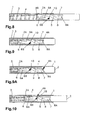
- Figures 2 to 4 show the deactivated position of the catch (6) that is produced by inserting the flat tip of the screwdriver (9) into the slot (6a) in the catch (6) through the triangular window (1a) in the outer cylinder (1) (figure 2) and the paths followed by the end (4a) of the strap (4) during the retention stroke of the piston (2) (figure 3) and during the propulsion stroke under the action of the spring (3) (figure 4).
- Figures 1 and 9 show that, naturally, the final positions of the retention stroke coincide whatever the activated (Figure 9A) or deactivated ( Figure 9) position of the catch (6); and a visual comparison of figures 8 and 10 shows the different length of the propulsion strokes according to whether the catch (6) is in its deactivated position (figure 8; longer stroke) or in its activated position (figure 10; shorter stroke).
Abstract
Description
- The field of the invention relates to devices used for opening and closing furniture doors and drawers and more specifically devices that have a telescopic mechanism determined by an exterior cylinder (that is attached to the body of a piece of furniture) and a piston that fits inside the cylinder and slides against a compression spring, so that a means of retention acts at the end of the piston's inward stroke in such a way that, if the outward end of the piston is pushed, this means of retention is released and the piston begins its outward stroke under the action of the spring.
- These devices work in a similar way to the mechanism by which ballpoint pens propel and retract the tip, which is achieved by means of a heart-shaped cam. This heart-shaped mechanism consists of a heart-shaped cam path followed, due to its geometrical form, by a freely rotating follower that travels around it.
- Until now, all attempts to use this mechanism for closing and opening furniture doors and drawers have resorted to the most simple and direct solution of using the ballpoint pen mechanism without first studying its degree of efficiency for the new application.
- In practice it has been shown that there are certain drawbacks with directly applying the ballpoint pen mechanism for this new purpose; one of these disadvantages is the fact that the relationship between the retention and propulsion strokes is not ideal, and also the length of the push needed to release the retention and bring about the propulsion stoke is too long; another drawback is that the ballpoint pen mechanism depends to a large extent on the accuracy with which the heart-shaped cam is made and on its position in relation to the freely rotating follower, whereby the device tends to be liable to suffer malfunctions and jamming.
- The invention proposes a solution that consists of the outer cylinder having a tensed strap whose end presses against an inner wall of the piston, whilst this piston has an elastic laminar ramp and a rotating catch; the ramp is tensed so that its free end presses on the inner wall of the piston in a part that is longitudinally aligned with the end of the strap at a suitable distance, and at the base of this ramp there is a pivot that defines a looped cam path between its periphery and the interior of the piston, which forms a Y-shaped recessed portion on the part opposite the base of the ramp that is designed to receive the end of the strap; the rotating catch operates between respective deactivated and activated positions wherein its front face is deviated or longitudinally facing the end of the ramp, and this rotating catch has a slot that is designed to allow the insertion of the flat tip of a screwdriver and can be accessed through a triangular window in the outer cylinder so that the positions of the slot corresponding to the deactivated and activated positions of the rotating catch are situated between two opposite sides. This design ensures that the rotating catch has a projection on its free end, which, in the piston's deactivated position, rests against the inner side of the end of a hook that emerges from the wall of the piston, the projection protruding to an extent that allows the end of the hook to pass it due to an elastic action; moreover, in the catch's activated position, its projection rests against the outer side of the end of the hook, whilst the catch rests against the inner wall of the piston whereon the strap is pressing in its resting state.
- Thanks to this design, when the piston is inserted into the fixed body, the tautness of the strap forces the end thereof to rise along the elastic laminar ramp following the looped cam path jointly defined by the follower and the pivot at its base; when the end of the strap reaches the recessed portion of the cam path opposite the base of the ramp, as the elastic actions of the compression spring and the strap act at once, the end of the strap is housed in the recessed portion and retains the position it has reached; when the end of the piston is pushed again, the end of the strap (due to the tautness thereof) takes the opposite branch of the "Y" shape to that by which it arrived and on passing it, the action of the compression spring causes the piston to move outwards, the end of the strap thereby reaching the opposite side of the ramp to that by which it rose and on reaching the end thereof, this ramp gives elastically and allows the end of the strap to pass it so that the piston may reach its extended resting position. When the catch is in its deactivated position, the piston achieves its greatest extension, wherein the end of the strap is situated at the inner end of the piston. However, when the catch is in its activated position, the front face thereof limits the end of the strap before reaching the inner end of the piston, thereby making the outward stroke thereof shorter than before.
- Therefore, the device proposed herein employs a mechanism that is different to the known heart-shaped cam mechanism and, furthermore, offers a simple construction with great functional reliability wherein rather than the path of the retention and propulsion strokes being a path followed by a freely rotating follower, it is basically the result of the elastic actions of the strap and the elastic laminar ramp; moreover, it enables the inclusion of a mechanism that makes it possible to selectively make use of two propulsion strokes of different lengths, so that one or other may be used in accordance with the needs of each situation. In order to switch the catch between its deactivated and activated positions, it is simply a matter of inserting the flat tip of a screwdriver or suchlike into its slot through the triangular window provided in the outer cylinder; as is logical, this is only carried out once (before the device is first installed), but it may subsequently be changed if the device is removed from the application and is to be used in another that requires a propulsion stroke of a different length. The projection on the catch serves to retain the deactivated and activated positions of the catch in conjunction with the end of the inner hook on the piston.
- An industrial embodiment of the invention is shown in the attached drawings as a non-limiting example to aid comprehension thereof.
- Figure 1
- shows a device according to the invention, seen from the side that has the triangular window (1a), with the rotating catch (6) in its deactivated position and with the piston (2) in the retracted position inside the outer cylinder (1); this figure also shows a screwdriver (9) in a relative position of activation in the slot (6a) through the triangular window (1a), and an enlarged detail that shows the inside of the device.
- Figure 2
- is a schematic view that shows the action of the screwdriver (9) in the slot (6a) in the catch (6) through the triangular window (1a), with the catch (6) in its deactivated position.
- Figure 3
- is an enlarged view of detail III of figure 1 and shows the path of the end (4a) of the strap (4) (marked with arrows) as the piston (2) is inserted into the outer cylinder (1).
- Figure 4
- is like figure 3, but it relates to the outward stroke of the piston (2).
- Figure 5
- is like figure 2, but with the catch (6) in its activated position.
- Figures 6 and 7
- are like figures 3 and 4, respectively, but they relate to the activated position of the catch (6) shown in figure 5.
- Figure 8
- shows the extended position of the piston (2) according to figures 1, 2, 3 and 4.
- Figure 9
- is like figure 1. Figure 9A is like figure 1, but it relates to the activated position of the catch (6).
- Figure 10
- is the extended position of the device according to figure 9A and Figures 5, 6 and 7.
- The following references are used in these figures:
- 1.- Outer cylinder
- 1a.- Triangular window in the outer cylinder (1)
- 2.- Piston
- 2a.- Inner wall of the piston (2)
- 3.- Compression spring
- 4.- Strap
- 4a.- End of the strap (4)
- 5.- Elastic laminar ramp
- 6.- Rotating catch
- 6a.- Slot in the catch (6)
- 6b.- Projection on the catch (6)
- 7.- Pivot in the piston (2)
- 8.- Cam path
- 8a.- Recessed portion of the cam path (8)
- 9.- Screwdriver
- 10.- Inner hook on the piston (2)
- The drawings and references listed above are described in the accompanying plans to illustrate a preferred embodiment of the proposed device.
- As shown in figure 1, the device is for opening and closing furniture doors and drawers and it responds to a general telescopic design comprising an outer cylinder (1) that is attached to the body of a piece of furniture and a piston (2) that fits inside it and slides against a compression spring (3) so that a means of retention acts at the end of its inward (or retention) stroke in such a way that, if the outward end of this piston (2) is pushed, this means of retention is released and the piston (2) begins its outward (or propulsion) stroke under the action of the spring (3).
- The particular design proposed herein is shown in figure 1 and consists of the outer cylinder (1) having a strap (4) that is tensed so that its end (4a) presses against an inner wall (2a) of the piston (2), whilst this piston (2) has an elastic laminar ramp (5) and a rotating catch (6); the ramp (5) is tensed so that its free end presses on the inner wall (2a) of the piston (2) in a part that is longitudinally aligned with the end (4a) of the strap (4) at a suitable distance, and at the base of this ramp (5) there is a pivot (7) that defines a looped cam path (8) between its periphery and the interior of the piston (2), which forms a Y-shaped recessed portion (8a) on the part opposite the base of the ramp (5) that is designed to receive the end (4a) of the strap (4); the rotating catch (6) operates between respective deactivated and activated positions wherein its front face is deviated or longitudinally facing the end of the ramp (5), and this rotating catch (6) has a slot (6a) that is designed to allow the insertion of the flat tip of a screwdriver (9) and can be accessed through a triangular window (1a) in the outer cylinder (1) so that the positions of the slot (6a) corresponding to the deactivated and activated positions of the rotating catch (6) are situated between two opposite sides. This design ensures that the rotating catch (6) has a projection (6b) on its free end, which, in the deactivated position of the piston (2), rests against the inner side of the end of a hook (10) that emerges from the wall of the piston (2), the projection (6b) protruding to an extent that allows the end of the hook (10) to pass it due to an elastic action. Moreover, in the activated position of the catch (6), its projection (6b) rests against the outer side of the end of the hook (10), whilst the catch (6) rests against the inner wall (2a) of the piston (2) whereon the strap (4) is pressing in its resting state.
- In order to explain how it works, we begin from the position shown in figure 1, wherein the catch (6) is in its deactivated position and the piston (2) is retracted to the end of its retention stroke, with the end (4a) of the strap (4) housed in the recessed portion (8a) of the cam path (8).
- Figures 2 to 4 show the deactivated position of the catch (6) that is produced by inserting the flat tip of the screwdriver (9) into the slot (6a) in the catch (6) through the triangular window (1a) in the outer cylinder (1) (figure 2) and the paths followed by the end (4a) of the strap (4) during the retention stroke of the piston (2) (figure 3) and during the propulsion stroke under the action of the spring (3) (figure 4).
- Now, in figure 5 as in figure 2, we turn the rotating catch (6) to its activated position using the flat tip of the screwdriver (9); in this situation the path followed by the end (4a) of the strap (4) during the retention stroke is as shown in figure 6 and, similarly, the path followed during the propulsion stroke is as shown in figure 7; as can be seen from these paths, the front face of the catch (6) limits the (4a) end of the strap (4) and prevents the piston (2) from continuing its outward stroke to the point that it reached when the catch (6) was in its deactivated position, as shown in figure 10.
- Figures 1 and 9 show that, naturally, the final positions of the retention stroke coincide whatever the activated (Figure 9A) or deactivated (Figure 9) position of the catch (6); and a visual comparison of figures 8 and 10 shows the different length of the propulsion strokes according to whether the catch (6) is in its deactivated position (figure 8; longer stroke) or in its activated position (figure 10; shorter stroke).
Claims (3)
- Device for opening and closing doors and drawers, of the type that has a telescopic design with an outer cylinder (1) that is attached to the body of a piece of furniture and a piston (2) that fits therein and slides against a compression spring (3), and at the end of the inward stroke thereof it is retained in such a way that by pushing the outward end of this piston (2), the retention is released and the piston (2) begins its outward stroke under the action of the spring (3), characterised in that the outer cylinder (1) has a strap (4) that is tensed so that its end (4a) presses against an inner wall (2a) of the piston (2), whilst this piston (2) has an elastic laminar ramp (5) and a rotating catch (6); the rotating catch (6) can adopt respective deactivated and activated positions wherein its front face is deviated or longitudinally facing the end of the ramp (5), and this rotating catch (6) has a slot (6a) that is designed to allow the insertion of the flat tip of a screwdriver (9) and can be accessed through a triangular window (1a) in the outer cylinder (1) so that the positions of the slot (6a) corresponding to the deactivated and activated positions of the rotating catch (6) are situated between two opposite sides; the ramp (5) is tensed so that its free end presses on the inner wall (2a) of the piston (2) in a part that is longitudinally aligned with the end (4a) of the strap (4) at a suitable distance, and at the base of this ramp (5) there is a pivot (7) that defines a looped cam path (8) between its periphery and the interior of the piston (2), which forms a Y-shaped recessed portion (8a) on the part opposite the base of the ramp (5) that is designed to receive the end (4a) of the strap (4).
- Device for opening and closing doors and drawers, according to claim one, characterised in that the rotating catch (6) has a projection (6b) on its free end, which, in the deactivated position of the piston (2), rests against the inner side of the end of a hook (10) that emerges from the wall of the piston (2), the projection (6b) protruding to an extent that allows the end of the hook (10) to pass it due to an elastic action.
- Device for opening and closing doors and drawers, according to all the previous claims, characterised in that in the activated position of the catch (6), its projection (6b) rests against the outer side of the end of the hook (10), whilst the catch (6) rests against the inner wall (2a) of the piston (2) whereon the strap (4) is pressing in its resting state.
Priority Applications (4)
| Application Number | Priority Date | Filing Date | Title |
|---|---|---|---|
| DE602006004891T DE602006004891D1 (en) | 2006-11-24 | 2006-11-24 | Device for opening and closing doors and drawers |
| ES06024464T ES2321020T3 (en) | 2006-11-24 | 2006-11-24 | OPENING AND CLOSING DEVICE OF DOORS AND DRAWERS. |
| AT06024464T ATE420576T1 (en) | 2006-11-24 | 2006-11-24 | DEVICE FOR OPENING AND CLOSING DOORS AND DRAWERS |
| EP06024464A EP1925240B1 (en) | 2006-11-24 | 2006-11-24 | Device for opening and closing doors and drawers |
Applications Claiming Priority (1)
| Application Number | Priority Date | Filing Date | Title |
|---|---|---|---|
| EP06024464A EP1925240B1 (en) | 2006-11-24 | 2006-11-24 | Device for opening and closing doors and drawers |
Publications (2)
| Publication Number | Publication Date |
|---|---|
| EP1925240A1 true EP1925240A1 (en) | 2008-05-28 |
| EP1925240B1 EP1925240B1 (en) | 2009-01-14 |
Family
ID=37852344
Family Applications (1)
| Application Number | Title | Priority Date | Filing Date |
|---|---|---|---|
| EP06024464A Not-in-force EP1925240B1 (en) | 2006-11-24 | 2006-11-24 | Device for opening and closing doors and drawers |
Country Status (4)
| Country | Link |
|---|---|
| EP (1) | EP1925240B1 (en) |
| AT (1) | ATE420576T1 (en) |
| DE (1) | DE602006004891D1 (en) |
| ES (1) | ES2321020T3 (en) |
Cited By (9)
| Publication number | Priority date | Publication date | Assignee | Title |
|---|---|---|---|---|
| EP2208440A1 (en) | 2009-01-19 | 2010-07-21 | Paul Hettich GmbH & Co. KG | Detent fitting and pull-out design |
| EP2266437A1 (en) * | 2009-06-26 | 2010-12-29 | Paul Hettich GmbH & Co. KG | Opening device for an extending guide and extending guide |
| EP2292119A1 (en) * | 2009-09-04 | 2011-03-09 | Paul Hettich GmbH & Co. KG | Locking device and pull-out design |
| ITVI20090229A1 (en) * | 2009-09-23 | 2011-03-24 | Estel S P A | DRAWER OPENING / CLOSING DEVICE |
| WO2012010590A1 (en) * | 2010-07-23 | 2012-01-26 | Paul Hettich Gmbh & Co. Kg | Catch mechanism |
| US8906167B2 (en) | 2010-04-28 | 2014-12-09 | Whirlpool Corporation | Slide assembly for a dishwasher rack |
| US9648952B2 (en) | 2012-04-30 | 2017-05-16 | Hardware Resources, Inc. | Pressure release slide latch mechanism |
| US9750347B2 (en) | 2012-04-30 | 2017-09-05 | Hardware Resources, Inc. | Pressure release slide latch mechanism |
| CN112878179A (en) * | 2021-04-07 | 2021-06-01 | 许昌学院 | Adjustable building truss structure for road and bridge engineering |
Families Citing this family (1)
| Publication number | Priority date | Publication date | Assignee | Title |
|---|---|---|---|---|
| DK2336011T3 (en) | 2009-12-18 | 2014-09-22 | Carman Entpr Co Ltd | Auxiliary drive for a trailer |
Citations (4)
| Publication number | Priority date | Publication date | Assignee | Title |
|---|---|---|---|---|
| EP0165190A1 (en) * | 1984-05-18 | 1985-12-18 | Philippe Rothschild | Extensible supporting device |
| US4984762A (en) * | 1989-05-03 | 1991-01-15 | Braun Thomas F | Rear drawer slide frame mounting screw with adjustable position compression spring |
| EP1362527A1 (en) * | 2002-05-17 | 2003-11-19 | Harn Lian Lam | Closing device for drawers |
| EP1541057A1 (en) * | 2003-12-05 | 2005-06-15 | Compagnucci S.p.a. | Device for automatic shock-absorbed closing of drawers and pull-out furniture elements |
-
2006
- 2006-11-24 DE DE602006004891T patent/DE602006004891D1/en active Active
- 2006-11-24 EP EP06024464A patent/EP1925240B1/en not_active Not-in-force
- 2006-11-24 AT AT06024464T patent/ATE420576T1/en not_active IP Right Cessation
- 2006-11-24 ES ES06024464T patent/ES2321020T3/en active Active
Patent Citations (4)
| Publication number | Priority date | Publication date | Assignee | Title |
|---|---|---|---|---|
| EP0165190A1 (en) * | 1984-05-18 | 1985-12-18 | Philippe Rothschild | Extensible supporting device |
| US4984762A (en) * | 1989-05-03 | 1991-01-15 | Braun Thomas F | Rear drawer slide frame mounting screw with adjustable position compression spring |
| EP1362527A1 (en) * | 2002-05-17 | 2003-11-19 | Harn Lian Lam | Closing device for drawers |
| EP1541057A1 (en) * | 2003-12-05 | 2005-06-15 | Compagnucci S.p.a. | Device for automatic shock-absorbed closing of drawers and pull-out furniture elements |
Cited By (10)
| Publication number | Priority date | Publication date | Assignee | Title |
|---|---|---|---|---|
| EP2208440A1 (en) | 2009-01-19 | 2010-07-21 | Paul Hettich GmbH & Co. KG | Detent fitting and pull-out design |
| EP2266437A1 (en) * | 2009-06-26 | 2010-12-29 | Paul Hettich GmbH & Co. KG | Opening device for an extending guide and extending guide |
| EP2292119A1 (en) * | 2009-09-04 | 2011-03-09 | Paul Hettich GmbH & Co. KG | Locking device and pull-out design |
| ITVI20090229A1 (en) * | 2009-09-23 | 2011-03-24 | Estel S P A | DRAWER OPENING / CLOSING DEVICE |
| US8906167B2 (en) | 2010-04-28 | 2014-12-09 | Whirlpool Corporation | Slide assembly for a dishwasher rack |
| WO2012010590A1 (en) * | 2010-07-23 | 2012-01-26 | Paul Hettich Gmbh & Co. Kg | Catch mechanism |
| CN103025204A (en) * | 2010-07-23 | 2013-04-03 | 保罗海蒂诗有限及两合公司 | Catch mechanism |
| US9648952B2 (en) | 2012-04-30 | 2017-05-16 | Hardware Resources, Inc. | Pressure release slide latch mechanism |
| US9750347B2 (en) | 2012-04-30 | 2017-09-05 | Hardware Resources, Inc. | Pressure release slide latch mechanism |
| CN112878179A (en) * | 2021-04-07 | 2021-06-01 | 许昌学院 | Adjustable building truss structure for road and bridge engineering |
Also Published As
| Publication number | Publication date |
|---|---|
| EP1925240B1 (en) | 2009-01-14 |
| ATE420576T1 (en) | 2009-01-15 |
| ES2321020T3 (en) | 2009-06-01 |
| DE602006004891D1 (en) | 2009-03-05 |
Similar Documents
| Publication | Publication Date | Title |
|---|---|---|
| EP1925240B1 (en) | Device for opening and closing doors and drawers | |
| EP2064405B1 (en) | Closing and opening device of the snap type for a moveable part of a piece of furniture | |
| TW200408772A (en) | Air damper for movable furniture parts | |
| KR100817202B1 (en) | Slide type writing tools having device for preventing dryness | |
| ES2688057T3 (en) | Sliding arrangement | |
| CN107847050B (en) | Ejection device for a movable furniture part | |
| BRPI0609634B8 (en) | finger activated lancet device | |
| DE60330291D1 (en) | Closing device for drawers | |
| EP2667118A3 (en) | Expansion valve and vibration-proof spring | |
| ATE311131T1 (en) | DRAWER PULL-OUT RIDES WITH AUTOMATIC CLOSURE WITH INTEGRATED DAMPING | |
| TW200640711A (en) | Retractable writing utensil | |
| HK1145067A1 (en) | Device for securing a soft ending of the opening movement of a drawer | |
| RU2012105910A (en) | SAFE NEEDLE ASSEMBLY AND WAYS OF ITS USE | |
| ATE527011T1 (en) | SLIDING CAPTURE CATHETER | |
| EP2452781A3 (en) | Staple gun wire guide | |
| CN107109881B (en) | Damping or resetting device for sliding door leaves | |
| ITMI20060719A1 (en) | DRIVER FOR AN END OF TRAVEL RETURN DEVICE AND END-OF-STROKE DAMPING IN A SLIDING DOOR | |
| US8661616B1 (en) | Door closer with push button hold open mechanism | |
| KR20100006176A (en) | Self-closing apparatus having a damper | |
| CN104670603B (en) | Caulking gun and attachment device for caulking gun | |
| RU2001118037A (en) | TAMPON APPLICATOR | |
| US8307495B1 (en) | Door cylinder | |
| WO2007022497A3 (en) | Pin clamp assembly | |
| ES2315055B1 (en) | RETROIMPULSOR OPENING FURNITURE DEVICE. | |
| TW200924669A (en) | Device for snap coupling and releasing a movable part to/from a fixed part of a furniture piece |
Legal Events
| Date | Code | Title | Description |
|---|---|---|---|
| PUAI | Public reference made under article 153(3) epc to a published international application that has entered the european phase |
Free format text: ORIGINAL CODE: 0009012 |
|
| 17P | Request for examination filed |
Effective date: 20070719 |
|
| AK | Designated contracting states |
Kind code of ref document: A1 Designated state(s): AT BE BG CH CY CZ DE DK EE ES FI FR GB GR HU IE IS IT LI LT LU LV MC NL PL PT RO SE SI SK TR |
|
| AX | Request for extension of the european patent |
Extension state: AL BA HR MK RS |
|
| GRAP | Despatch of communication of intention to grant a patent |
Free format text: ORIGINAL CODE: EPIDOSNIGR1 |
|
| GRAS | Grant fee paid |
Free format text: ORIGINAL CODE: EPIDOSNIGR3 |
|
| GRAA | (expected) grant |
Free format text: ORIGINAL CODE: 0009210 |
|
| AK | Designated contracting states |
Kind code of ref document: B1 Designated state(s): AT BE BG CH CY CZ DE DK EE ES FI FR GB GR HU IE IS IT LI LT LU LV MC NL PL PT RO SE SI SK TR |
|
| REG | Reference to a national code |
Ref country code: GB Ref legal event code: FG4D |
|
| REG | Reference to a national code |
Ref country code: CH Ref legal event code: EP |
|
| AKX | Designation fees paid |
Designated state(s): AT BE BG CH CY CZ DE DK EE ES FI FR GB GR HU IE IS IT LI LT LU LV MC NL PL PT RO SE SI SK TR |
|
| REG | Reference to a national code |
Ref country code: IE Ref legal event code: FG4D |
|
| REF | Corresponds to: |
Ref document number: 602006004891 Country of ref document: DE Date of ref document: 20090305 Kind code of ref document: P |
|
| PG25 | Lapsed in a contracting state [announced via postgrant information from national office to epo] |
Ref country code: NL Free format text: LAPSE BECAUSE OF FAILURE TO SUBMIT A TRANSLATION OF THE DESCRIPTION OR TO PAY THE FEE WITHIN THE PRESCRIBED TIME-LIMIT Effective date: 20090114 |
|
| REG | Reference to a national code |
Ref country code: ES Ref legal event code: FG2A Ref document number: 2321020 Country of ref document: ES Kind code of ref document: T3 |
|
| NLV1 | Nl: lapsed or annulled due to failure to fulfill the requirements of art. 29p and 29m of the patents act | ||
| PG25 | Lapsed in a contracting state [announced via postgrant information from national office to epo] |
Ref country code: SI Free format text: LAPSE BECAUSE OF FAILURE TO SUBMIT A TRANSLATION OF THE DESCRIPTION OR TO PAY THE FEE WITHIN THE PRESCRIBED TIME-LIMIT Effective date: 20090114 Ref country code: LT Free format text: LAPSE BECAUSE OF FAILURE TO SUBMIT A TRANSLATION OF THE DESCRIPTION OR TO PAY THE FEE WITHIN THE PRESCRIBED TIME-LIMIT Effective date: 20090114 Ref country code: FI Free format text: LAPSE BECAUSE OF FAILURE TO SUBMIT A TRANSLATION OF THE DESCRIPTION OR TO PAY THE FEE WITHIN THE PRESCRIBED TIME-LIMIT Effective date: 20090114 |
|
| PG25 | Lapsed in a contracting state [announced via postgrant information from national office to epo] |
Ref country code: SE Free format text: LAPSE BECAUSE OF FAILURE TO SUBMIT A TRANSLATION OF THE DESCRIPTION OR TO PAY THE FEE WITHIN THE PRESCRIBED TIME-LIMIT Effective date: 20090414 Ref country code: PL Free format text: LAPSE BECAUSE OF FAILURE TO SUBMIT A TRANSLATION OF THE DESCRIPTION OR TO PAY THE FEE WITHIN THE PRESCRIBED TIME-LIMIT Effective date: 20090114 Ref country code: PT Free format text: LAPSE BECAUSE OF FAILURE TO SUBMIT A TRANSLATION OF THE DESCRIPTION OR TO PAY THE FEE WITHIN THE PRESCRIBED TIME-LIMIT Effective date: 20090615 Ref country code: IS Free format text: LAPSE BECAUSE OF FAILURE TO SUBMIT A TRANSLATION OF THE DESCRIPTION OR TO PAY THE FEE WITHIN THE PRESCRIBED TIME-LIMIT Effective date: 20090514 Ref country code: LV Free format text: LAPSE BECAUSE OF FAILURE TO SUBMIT A TRANSLATION OF THE DESCRIPTION OR TO PAY THE FEE WITHIN THE PRESCRIBED TIME-LIMIT Effective date: 20090114 Ref country code: AT Free format text: LAPSE BECAUSE OF FAILURE TO SUBMIT A TRANSLATION OF THE DESCRIPTION OR TO PAY THE FEE WITHIN THE PRESCRIBED TIME-LIMIT Effective date: 20090114 |
|
| PG25 | Lapsed in a contracting state [announced via postgrant information from national office to epo] |
Ref country code: BE Free format text: LAPSE BECAUSE OF FAILURE TO SUBMIT A TRANSLATION OF THE DESCRIPTION OR TO PAY THE FEE WITHIN THE PRESCRIBED TIME-LIMIT Effective date: 20090114 |
|
| PG25 | Lapsed in a contracting state [announced via postgrant information from national office to epo] |
Ref country code: CZ Free format text: LAPSE BECAUSE OF FAILURE TO SUBMIT A TRANSLATION OF THE DESCRIPTION OR TO PAY THE FEE WITHIN THE PRESCRIBED TIME-LIMIT Effective date: 20090114 Ref country code: DK Free format text: LAPSE BECAUSE OF FAILURE TO SUBMIT A TRANSLATION OF THE DESCRIPTION OR TO PAY THE FEE WITHIN THE PRESCRIBED TIME-LIMIT Effective date: 20090114 Ref country code: EE Free format text: LAPSE BECAUSE OF FAILURE TO SUBMIT A TRANSLATION OF THE DESCRIPTION OR TO PAY THE FEE WITHIN THE PRESCRIBED TIME-LIMIT Effective date: 20090114 |
|
| PLBE | No opposition filed within time limit |
Free format text: ORIGINAL CODE: 0009261 |
|
| STAA | Information on the status of an ep patent application or granted ep patent |
Free format text: STATUS: NO OPPOSITION FILED WITHIN TIME LIMIT |
|
| PG25 | Lapsed in a contracting state [announced via postgrant information from national office to epo] |
Ref country code: RO Free format text: LAPSE BECAUSE OF FAILURE TO SUBMIT A TRANSLATION OF THE DESCRIPTION OR TO PAY THE FEE WITHIN THE PRESCRIBED TIME-LIMIT Effective date: 20090114 |
|
| 26N | No opposition filed |
Effective date: 20091015 |
|
| PG25 | Lapsed in a contracting state [announced via postgrant information from national office to epo] |
Ref country code: BG Free format text: LAPSE BECAUSE OF FAILURE TO SUBMIT A TRANSLATION OF THE DESCRIPTION OR TO PAY THE FEE WITHIN THE PRESCRIBED TIME-LIMIT Effective date: 20090414 |
|
| PG25 | Lapsed in a contracting state [announced via postgrant information from national office to epo] |
Ref country code: MC Free format text: LAPSE BECAUSE OF NON-PAYMENT OF DUE FEES Effective date: 20091130 |
|
| PG25 | Lapsed in a contracting state [announced via postgrant information from national office to epo] |
Ref country code: IE Free format text: LAPSE BECAUSE OF NON-PAYMENT OF DUE FEES Effective date: 20091124 Ref country code: GR Free format text: LAPSE BECAUSE OF FAILURE TO SUBMIT A TRANSLATION OF THE DESCRIPTION OR TO PAY THE FEE WITHIN THE PRESCRIBED TIME-LIMIT Effective date: 20090415 |
|
| PGFP | Annual fee paid to national office [announced via postgrant information from national office to epo] |
Ref country code: DE Payment date: 20101126 Year of fee payment: 5 Ref country code: SK Payment date: 20101103 Year of fee payment: 5 |
|
| PGFP | Annual fee paid to national office [announced via postgrant information from national office to epo] |
Ref country code: GB Payment date: 20101124 Year of fee payment: 5 Ref country code: IT Payment date: 20101123 Year of fee payment: 5 |
|
| PG25 | Lapsed in a contracting state [announced via postgrant information from national office to epo] |
Ref country code: LU Free format text: LAPSE BECAUSE OF NON-PAYMENT OF DUE FEES Effective date: 20091124 |
|
| PG25 | Lapsed in a contracting state [announced via postgrant information from national office to epo] |
Ref country code: HU Free format text: LAPSE BECAUSE OF FAILURE TO SUBMIT A TRANSLATION OF THE DESCRIPTION OR TO PAY THE FEE WITHIN THE PRESCRIBED TIME-LIMIT Effective date: 20090715 |
|
| REG | Reference to a national code |
Ref country code: CH Ref legal event code: PL |
|
| PG25 | Lapsed in a contracting state [announced via postgrant information from national office to epo] |
Ref country code: CH Free format text: LAPSE BECAUSE OF NON-PAYMENT OF DUE FEES Effective date: 20101130 Ref country code: LI Free format text: LAPSE BECAUSE OF NON-PAYMENT OF DUE FEES Effective date: 20101130 |
|
| PG25 | Lapsed in a contracting state [announced via postgrant information from national office to epo] |
Ref country code: TR Free format text: LAPSE BECAUSE OF FAILURE TO SUBMIT A TRANSLATION OF THE DESCRIPTION OR TO PAY THE FEE WITHIN THE PRESCRIBED TIME-LIMIT Effective date: 20090114 |
|
| PG25 | Lapsed in a contracting state [announced via postgrant information from national office to epo] |
Ref country code: CY Free format text: LAPSE BECAUSE OF FAILURE TO SUBMIT A TRANSLATION OF THE DESCRIPTION OR TO PAY THE FEE WITHIN THE PRESCRIBED TIME-LIMIT Effective date: 20090114 |
|
| PGFP | Annual fee paid to national office [announced via postgrant information from national office to epo] |
Ref country code: ES Payment date: 20111104 Year of fee payment: 6 Ref country code: FR Payment date: 20111128 Year of fee payment: 6 |
|
| GBPC | Gb: european patent ceased through non-payment of renewal fee |
Effective date: 20121124 |
|
| PG25 | Lapsed in a contracting state [announced via postgrant information from national office to epo] |
Ref country code: SK Free format text: LAPSE BECAUSE OF NON-PAYMENT OF DUE FEES Effective date: 20121124 |
|
| REG | Reference to a national code |
Ref country code: SK Ref legal event code: MM4A Ref document number: E 5427 Country of ref document: SK Effective date: 20121124 |
|
| REG | Reference to a national code |
Ref country code: FR Ref legal event code: ST Effective date: 20130731 |
|
| PG25 | Lapsed in a contracting state [announced via postgrant information from national office to epo] |
Ref country code: IT Free format text: LAPSE BECAUSE OF NON-PAYMENT OF DUE FEES Effective date: 20121124 |
|
| REG | Reference to a national code |
Ref country code: DE Ref legal event code: R119 Ref document number: 602006004891 Country of ref document: DE Effective date: 20130601 |
|
| PG25 | Lapsed in a contracting state [announced via postgrant information from national office to epo] |
Ref country code: DE Free format text: LAPSE BECAUSE OF NON-PAYMENT OF DUE FEES Effective date: 20130601 |
|
| PG25 | Lapsed in a contracting state [announced via postgrant information from national office to epo] |
Ref country code: FR Free format text: LAPSE BECAUSE OF NON-PAYMENT OF DUE FEES Effective date: 20121130 Ref country code: GB Free format text: LAPSE BECAUSE OF NON-PAYMENT OF DUE FEES Effective date: 20121124 |
|
| REG | Reference to a national code |
Ref country code: ES Ref legal event code: FD2A Effective date: 20140527 |
|
| PG25 | Lapsed in a contracting state [announced via postgrant information from national office to epo] |
Ref country code: ES Free format text: LAPSE BECAUSE OF NON-PAYMENT OF DUE FEES Effective date: 20121125 |