EP1923657A1 - Une base d'arme éloignée compacte, intégralement stabilisée et équipée de quatre axes, avec ligne de visée indépendante - Google Patents
Une base d'arme éloignée compacte, intégralement stabilisée et équipée de quatre axes, avec ligne de visée indépendante Download PDFInfo
- Publication number
- EP1923657A1 EP1923657A1 EP06124200A EP06124200A EP1923657A1 EP 1923657 A1 EP1923657 A1 EP 1923657A1 EP 06124200 A EP06124200 A EP 06124200A EP 06124200 A EP06124200 A EP 06124200A EP 1923657 A1 EP1923657 A1 EP 1923657A1
- Authority
- EP
- European Patent Office
- Prior art keywords
- weapon
- sight
- remote
- sight unit
- axis
- Prior art date
- Legal status (The legal status is an assumption and is not a legal conclusion. Google has not performed a legal analysis and makes no representation as to the accuracy of the status listed.)
- Granted
Links
- 230000001419 dependent effect Effects 0.000 claims description 3
- 230000002093 peripheral effect Effects 0.000 description 6
- 230000004438 eyesight Effects 0.000 description 4
- 238000010304 firing Methods 0.000 description 3
- 230000000087 stabilizing effect Effects 0.000 description 3
- 230000009286 beneficial effect Effects 0.000 description 2
- 238000004904 shortening Methods 0.000 description 2
- 230000000007 visual effect Effects 0.000 description 2
- 230000004308 accommodation Effects 0.000 description 1
- 230000000694 effects Effects 0.000 description 1
- 238000005286 illumination Methods 0.000 description 1
- 238000009434 installation Methods 0.000 description 1
- 238000000034 method Methods 0.000 description 1
- 230000008092 positive effect Effects 0.000 description 1
- 230000003019 stabilising effect Effects 0.000 description 1
- 230000008685 targeting Effects 0.000 description 1
Images

Classifications
-
- F—MECHANICAL ENGINEERING; LIGHTING; HEATING; WEAPONS; BLASTING
- F41—WEAPONS
- F41G—WEAPON SIGHTS; AIMING
- F41G3/00—Aiming or laying means
- F41G3/14—Indirect aiming means
- F41G3/16—Sighting devices adapted for indirect laying of fire
- F41G3/165—Sighting devices adapted for indirect laying of fire using a TV-monitor
-
- F—MECHANICAL ENGINEERING; LIGHTING; HEATING; WEAPONS; BLASTING
- F41—WEAPONS
- F41G—WEAPON SIGHTS; AIMING
- F41G3/00—Aiming or laying means
- F41G3/22—Aiming or laying means for vehicle-borne armament, e.g. on aircraft
-
- F—MECHANICAL ENGINEERING; LIGHTING; HEATING; WEAPONS; BLASTING
- F41—WEAPONS
- F41G—WEAPON SIGHTS; AIMING
- F41G5/00—Elevating or traversing control systems for guns
- F41G5/14—Elevating or traversing control systems for guns for vehicle-borne guns
Definitions
- the present invention relates to a remote weapon station according to the precharacterising part of claim 1.
- the present invention relates, but not limited, to industries making remotely controlled weapon stations, machine-guns, automatic grenade launchers, missile firing equipment etc.
- a three axes remote weapon station comprises a gun being turnable about a first transverse axis and a second elevation axis and a sight unit rotatable about a third elevation axis, wherein the third axis is primary used when firing grenade launcher type weapons.
- the four axes weapon stations is provided for that the line of sight can be controlled independently of the bore axis of the weapon, wherein the bore axis weapon is stabilised in two axes.
- Prior art systems having four axes arrangement wherein solely the weapon's bore axis is two axes stabilized involve that the field of vision must be selected such that the target remain within the field of vision when the vehicle is moving (roll/pitch/heading). Also this means that it is difficult to measure the distance to the target when the vehicle moves, especially when angles for super elevation and lead angles are added to compensate for relative motion between the target and the weapon station. Furthermore, prior art systems wherein solely the sight unit's line of sight is two axes stabilized involve that it is difficult to hit the target with fired ammunition.
- US 5273236 discloses an apparatus provided for designating a plurality of objects within a field of view and thereafter simultaneously tracking each of the objects.
- a further document, US 4576346 describes a seeker head for a target seeking missile, which comprises a seeker adapted to be directed to a target.
- the object of the present invention is to overcome the drawbacks of known techniques.
- the remote weapon station is characterised by the features of claim's 1 characterising part.
- a not bulky remote weapon station is achieved at the same time as the operator of the remote weapon station is able to perform targeting and surveillance without changing the remote weapon station's silhouette and thus reducing the risk of being detected by visual means.
- the concentration of masses will also be symmetrically arranged which will make the remote weapon station possible to stabilise without adding extra weight in the form of undesired counter weights or larger drives. Thereby increase the usage of the weapon station when the platform on which the weapon station is mounted is moving. Therby is also achieved a possibility to utilise the sensor without pointing a gun directly at the object of interest. Also there is a possibility to start searching for a new target while firing the gun at the first acquired target.
- a positive effect is that a weapon station can be provided with a high precision stabilised system having a sighting function with an unitary installation of a sight unit matching the performance of the weapon and at the same time providing a sufficient performance for e.g. missile guidance.
- the sight unit in an effective manner can follow a target by controlling the weapon via a control unit for aiming-off, at the same time as compensation means provides for compensation of eventual uneven motion of the remote weapon station, for example being mounted at a gun boat.
- the control unit can control the sight unit independently of the gun aiming by means of the arrangement of the remote weapon station according to the present invention.
- a compact remote weapon station is thus achieved having a sight unit with a totally independent line of sight relatively the pointing of the gun having the sight unit correctly balanced relatively the weapon and providing an exact line of sight.
- a remote weapon station having a sight unit, which weapon station can be used utilizing the sight unit without the need of other kinds of compensation for lead angles and/or super elevation.
- the objects of the invention is to provide a compact remote weapon station, wherein the assembly permits that the angle between the bore axis of the weapon and the line of sight of the sight in a controllable manner can be made independently of each other.
- the weapon's bore axis being stabilized in two axes and the sight unit's line of sight being stabilized in two axes.
- the target can be placed in the centre of a image generating display and the distance to the target continuously can be measured by a laser range finder etc, wherein the weapon's bore axis can be directed in such a way that the fired ammunition hits the target with precision. Also is achieved that the bore axis of the weapon and the line of sight of the sight unit can be oriented relative each other in such a way that the sight unit can be used without the need of directing the weapon towards the target.
- the sight unit's line of sight can be stabilized and directed with a higher accuracy than being provided by systems only stabilising the weapon's bore axis.
- the weapon support is rotatable about the first transverse axis independently of the rotatable motion of the sight unit about the third transverse axis such that the weapon can be directed essentially in another direction relatively the search direction of the sight unit.
- the weapon can be rotated to the opposite direction relatively to the sight unit's target tracking(or search) direction.
- This is also a beneficial feature for shortening the time when for example a supporting leg of the weapon carriage covers the line of sight, by controlling the weapon support's and sight unit's relative rotation.
- the weapon support also is arranged to be controlled to rotate about the first transverse axis dependent upon the rotatable motion of the sight unit about the third transverse axis.
- the first axis coincides with the third axis.
- a remote weapon station being capable to utilize a compact motor driving system using the same axis for the transverse rotations.
- the sight unit comprises a first essentially spherical, hollow body which interacts with a second essentially rotationally symmetrical body, both bodies being rotatable in relation to one another about the transverse axis, the spherical body accommodating at least one electro-optical sensor, being rotatable about the fourth elevation axis.
- the sight unit can be independently stabilised, thereby making the remote weapon station optimized for high precision sensor systems, e.g. laser illumination at long ranges.
- the use of a sensor sight system with a spherical form arranged in the remote weapon station provides independent 360° traverse operation with an optimal configuration of the remote weapon station with regard to overall volume, interior sensor volume utilisation, ballistic protection, signature management, and weapon dumping/elevation angles.
- the weapon support comprises a tiltable leg arrangement supporting the weapon attachment device, the leg arrangement being tiltable over the first essentially spherical, hollow body.
- the remote weapon station can be made lower for transportation purposes by tilting the weapon attachment device over the sight unit.
- the tilting action performing an imaginary circular arc essentially with the same radius as the radius of the first essentially spherical, hollow body.
- the sight unit comprises a first essentially cylindrical, hollow body accommodating at least one electro-optical sensor.
- the hollow body encloses all interior movable parts, such as electro-optical sensors, of the sight unit for hiding said parts.
- the body is preferably armour cased and transparent and/or partly transparent.
- the weapon support being comprised in a motorized gun control system.
- the remote weapon station is applicable to an available platform, such as a truck, an armoured car, gun boat, tank, helicopter etc.
- the sight unit is arranged for controlling at least one weapon disposed at a distance from the remote weapon station.
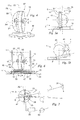
- a remote weapon station 1 is schematically illustrated.
- the remote weapon station 1 is mountable onto a gun boat (not shown) or the like.
- the remote weapon station 1 comprises a weapon support 3 adapted for rotatable motion about a first transverse axis X1.
- the weapon support 3 supports a weapon attachment device 5 being rotatable about a second elevation axis X2.
- the second elevation axis X2 comprises an U-shaped part 7 for accommodation of a gun 9.
- the gun 9 is mounted onto the weapon attachment device 5, such as a bayonet fitting (not shown) connected to the second elevation axis X2, wherein the gun 9 easily can be disconnected from the weapon attachment device 5.
- the weapon support 3 supports two legs 11 extending from a platform 13 of the weapon support 3, which platform 13 being rotatable about the axis X1. Between the legs 11 and at their upper ends 15 is the U-shaped part 7 mounted. One of the legs 11 accommodates an ammunition belt guide (not shown).
- the remote weapon station 1 comprises a sight unit 17 for observation of the surroundings and for measuring in a detected target, tracking, classifying the type of target, identifying the target etc.
- the sight unit 17 is rotatable about a third transverse axis X3 and about a fourth elevation axis X4.
- the sight unit 17 has at least one electro-optical sensor 19 with associated apertures 21 arranged in the sight unit's 17 spherical hollow body 23.
- the sight unit 17 is mounted between the weapon support 3 (platform or fundament) and the weapon (gun) attachment device 5, whereby is achieved a compact remote weapon station 1 having a sight unit 17 with a totally independent line of sight relatively the bore axis of the gun 9.
- a control unit 25 is arranged remote from the weapon station 1 and is adapted to control a weapon driving means 27 for rotating the gun 9 about the first transverse axis X1 and the second elevation axis X2 and also to control a sight unit driving means 29 for rotation about the third transverse axis X3 and the fourth elevation axis X4.
- FIGS. 2a, 2b, 2c are shown in a plane view the remote weapon station 1 performing a sight unit rotation towards a target/object 31 while pointing the gun 9 in a somewhat opposite direction.
- both the gun 9 and the sight unit 17 are directed in the same direction.
- the sight unit 17 has started it's rotation r for localising the target 31 without pointing the gun 9 at the target 31. In some cases this performance can be beneficial since pointing a gun at an object may result in a non-desirable reaction.
- FIG. 2b is shown how the sight line L will be covered by one of the legs 11 of the weapon support 3.
- This problem is partly solved by using e.g. two sensors or two in pair arranged sensors 19, such as one TV- and one IR-sensor or two in pair arranged TV- and IR-sensors.
- the first sensor or pair of sensors observes the surroundings, the second sensor or pair of sensors instantaneously will lose contact with the target 31 since the sight line L is covered by the leg 11.
- the second sensor or pair of sensors pick up the line of sight to the target L.
- the control unit 25 controls the weapon support 3 to rotate in an opposite direction marked with arrow r2, see FIG. 2c (an overlapping function).
- the legs 11 can be arranged as a system of framework.
- the apertures and sensors can be parked occasionally behind one of the legs 11.
- the sight unit 17 is rotatable about the third transverse axis X3 and about, perpendicular to the third axis X3, the fourth elevation axis X4, independently of the position or rotation of the weapon support 3 about the first transverse axis X1 and the second elevation axis X2.
- a spherical hollow body 23 embodying the sight sensors 19 an independent 360° traverse operation of the sight unit 17 is possible without moving the gun 9, wherein the silhouette of the remote weapon station 1 not being changed, thus minimizing the risk of being detected by the object/target 31 by visual means.
- FIGS. 1 and 2 show a sight unit 17 comprising an spherical hollow body 23 embodying the sensors 19, as an alternative the sight unit 17 may comprise a first essentially cylindrical or cubical, hollow body 23 accommodating at least one electro-optical sensor 19.
- FIGS. 3a, 3b, 3c Such an embodiment is shown in FIGS. 3a, 3b, 3c. Thereby is achieved a large volume for sight equipment even still performing an optimal signature management, that is having essentially the same silhouette independently of the sensor transverse motion about the third axis X3.
- the FIG. 3c shows the sight unit 17 directed to the opposite direction relatively the gun 9 in a horizontal action.
- FIGS. 3a, 3b, 3c The embodiment of FIGS. 3a, 3b, 3c is arranged such that the first transverse axis X1 coincides with the third transverse axis X3 of the sight unit 17, whereby is provided a remote weapon station 1 being capable to utilize a compact motor driving system using the same axis for the transverse rotations as being described below with reference to FIG. 6.
- a cylindrical hollow body 33 encloses all interior movable parts, such as electro-optical sensors, of the sight unit for protecting said parts.
- the body is transparent and armour cased. In such a way, on one hand the interior equipment is protected from splinters, small arms fire or ricochets etc., and on the other hand hidden from being detected by the object/target.
- the sight unit 17 comprises an essentially spherical body 23 adjacent to one end of a rotationally symmetrical body 35, preferably of circular cylindrical shape.
- the spherical body 23 comprises a circular central section 37 surrounded by two peripheral half sections 39 on each side (only one section 39 is illustrated with broken line).
- Each peripheral half section is provided with two apertures 21.
- the sections each only have one aperture.
- the spherical hollow body 23 is rotatable in relation to the rotationally symmetrical body 35 about the third transverse axis X3.
- the two peripheral half sections 39 are rigidly mechanically interconnected and arranged rotatable so as to be capable of being rotated about the fourth elevation axis A4.
- the elevation can be limited to a range wherein the apertures 21 are in one end position oriented at an angle downwards relative to the horizontal plane and, in the other end position, oriented at an angle upwards relative to the horizontal plane.
- the electro-optical sensors 19 can be selected from a variety of sensors, e.g. TV, IRV, laser rangefinder and laser illuminator.
- the use of the sight unit 17 with a spherical form arranged in the remote weapon station 1 provides independent 360° traverse operation with an optimal configuration of the remote weapon station 1 with regard to overall volume, interior sensor volume utilisation, ballistic protection, signature management, and weapon dumping/elevation angles.
- FIG. 5a and 5b are shown an embodiment of the remote weapon station 1, wherein the weapon support 3 comprises a tiltable leg arrangement 41 supporting the weapon attachment device 5.
- the leg arrangement 41 comprises two legs 11 being tiltable about a tilting point p over the essentially spherical, hollow body 23 being also shown in FIG. 4.
- the tilting action of the weapon attachment device 5 over the sight unit 17 performs an imaginary circular arc c essentially with the same radius as the radius of the circumference of the essentially spherical, hollow body 23.
- the remote weapon station 1 can be made lower in a transportation mode without the need of making the volume of the sight equipment smaller.
- FIG. 6 is schematically illustrated a compact motor driving system 43 using the same axis X1, X3 for the transverse rotations of both the sensor unit 17 and the weapon support 3.
- the first axis X1 coincides with the third axis X3.
- a first rotor 45 is arranged rotatable about the common transverse axis X1 and X3 and is connected to the legs 11 of the weapon support 3 and via a first bearing 47 connected to the weapon carrier 49, such as a gun boat.
- a first stator 51 actuates the first rotor 45 for transverse rotation of the gun 9.
- a further second bearing 53 is arranged between the first rotor 45 and a second rotor 55 carrying the circular central section 37, within which the electro-optical sensors 19 are rotatable arranged for elevation rotation about the fourth elevation axis X4.
- a second stator 57 actuates the second rotor 55 for the transverse rotation of the circular central section 37 and the peripheral sections (not shown) of the sight unit 17.
- FIG. 7 is shown schematically the aiming of the remote weapon station 1 at a moving target 31.
- the gun's 9 pointing direction and the sight line L of the sight unit 17 is broken for sake of clarity and the target 31 is drawn smaller than the remote weapon station 1 for the sake of illustration.
- An aiming-off angle ⁇ is required as the target 31 is moving.
- the compact remote weapon station's 1 sight unit 17 detecting the target 31 is rotated independently of the gun's 9 motion.
- the control unit 25 is estimated the required aiming-off angle ⁇ , dependent upon the velocity of the target 31 and eventually the velocity of the carrier carrying the remote weapon station 1. Also parameters as wind direction and speed etc. are considered.
- An uniaxial rate gyro is stabilizing the gun 9 via an elevation drive unit 27 and a transverse drive unit arranged at the second elevation axis X2 and the transverse axis, and the electro-optical sensors 19 are stabilized via a sensor unit elevation drive system (not shown) of an elevation drive system and transverse drive system arranged within the circular central section 37 of the sight unit 17.
- the remote weapon station 1 is according to one embodiment of the invention provided with a weapon support 3 being comprised in a motorized gun control system. Thereby is achieved that the remote weapon station 1 is applicable to an available carrier, such as a truck, car, gun boat, tank, helicopter etc.
- the sight unit 17 of the remote weapon station 1 can control at least one separate weapon 60 placed at a distance from the remote weapon station 1.Control is achieved by means of being directly connected to the weapon, illuminating the target for the weapon or providing in-the-air guidance to the weapon or a combination of any of these means.
- the invention is not limited to a specific embodiment herein, but may also consist of several combinations of the presented embodiments.
- only one peripheral half section can provide an aperture and none in the other section.
- the elevation drive system and transverse drive system may be arranged in one of the supports of the sight unit.
- the sight unit's hollow body can have a central section being rotatable and two outer section acting as supports (fork-shaped assembly) or the section being supported by only one peripheral support.
- the sigh unit may be placed between the weapon support and the weapon attachment device by mounting the sight unit "hanging" under the weapon attachment device or adjacent the same.
Landscapes
- Engineering & Computer Science (AREA)
- General Engineering & Computer Science (AREA)
- Aviation & Aerospace Engineering (AREA)
- Aiming, Guidance, Guns With A Light Source, Armor, Camouflage, And Targets (AREA)
Priority Applications (2)
| Application Number | Priority Date | Filing Date | Title |
|---|---|---|---|
| EP06124200.4A EP1923657B1 (fr) | 2006-11-16 | 2006-11-16 | Une base d'arme éloignée compacte, intégralement stabilisée et équipée de quatre axes, avec ligne de visée indépendante |
| US11/984,397 US20080148931A1 (en) | 2006-11-16 | 2007-11-16 | Compact, fully stablised, four axes, remote weapon station with independent line of sight |
Applications Claiming Priority (1)
| Application Number | Priority Date | Filing Date | Title |
|---|---|---|---|
| EP06124200.4A EP1923657B1 (fr) | 2006-11-16 | 2006-11-16 | Une base d'arme éloignée compacte, intégralement stabilisée et équipée de quatre axes, avec ligne de visée indépendante |
Publications (2)
| Publication Number | Publication Date |
|---|---|
| EP1923657A1 true EP1923657A1 (fr) | 2008-05-21 |
| EP1923657B1 EP1923657B1 (fr) | 2017-05-03 |
Family
ID=37897300
Family Applications (1)
| Application Number | Title | Priority Date | Filing Date |
|---|---|---|---|
| EP06124200.4A Revoked EP1923657B1 (fr) | 2006-11-16 | 2006-11-16 | Une base d'arme éloignée compacte, intégralement stabilisée et équipée de quatre axes, avec ligne de visée indépendante |
Country Status (2)
| Country | Link |
|---|---|
| US (1) | US20080148931A1 (fr) |
| EP (1) | EP1923657B1 (fr) |
Cited By (6)
| Publication number | Priority date | Publication date | Assignee | Title |
|---|---|---|---|---|
| WO2012015777A1 (fr) * | 2010-07-27 | 2012-02-02 | Raytheon Company | Poste d'armes et procédé associé |
| DE102012102235B3 (de) | 2012-03-16 | 2013-01-17 | Krauss-Maffei Wegmann Gmbh & Co. Kg | Militärisches Fahrzeug und Verfahren zur Ausrichtung eines Ausrüstungsgegenstands |
| WO2013058856A3 (fr) * | 2011-08-09 | 2013-06-20 | Raytheon Company | Système de positionnement d'arme et procédés d'utilisation |
| RU167543U1 (ru) * | 2015-08-25 | 2017-01-10 | Открытое Акционерное Общество "Пеленг" | Устройство слежения за положением орудия |
| EP3123097B1 (fr) | 2014-03-28 | 2018-05-09 | Safran Electronics & Defense | Tourelleau optronique arme |
| WO2023139191A1 (fr) * | 2022-01-21 | 2023-07-27 | Compagnie Industrielle Des Lasers Cilas | Arme laser portée par une nacelle |
Families Citing this family (13)
| Publication number | Priority date | Publication date | Assignee | Title |
|---|---|---|---|---|
| US7966763B1 (en) | 2008-05-22 | 2011-06-28 | The United States Of America As Represented By The Secretary Of The Navy | Targeting system for a projectile launcher |
| US8336442B2 (en) * | 2008-11-21 | 2012-12-25 | The United States Of America As Represented By The Secretary Of The Army | Automatically-reloadable, remotely-operated weapon system having an externally-powered firearm |
| US8787114B1 (en) | 2010-09-13 | 2014-07-22 | The Boeing Company | Audio surveillance system |
| US8620023B1 (en) * | 2010-09-13 | 2013-12-31 | The Boeing Company | Object detection and location system |
| DE102013101635A1 (de) | 2013-02-19 | 2014-08-21 | Krauss-Maffei Wegmann Gmbh & Co. Kg | Waffenstation |
| US9568267B2 (en) | 2014-07-22 | 2017-02-14 | Moog Inc. | Configurable weapon station having under armor reload |
| US9464856B2 (en) | 2014-07-22 | 2016-10-11 | Moog Inc. | Configurable remote weapon station having under armor reload |
| DE102015119847A1 (de) | 2015-09-18 | 2017-03-23 | Rheinmetall Defence Electronics Gmbh | Fernbedienbare Waffenstation und Verfahren zum Betreiben einer fernbedienbaren Waffenstation |
| US11274904B2 (en) | 2019-10-25 | 2022-03-15 | Aimlock Inc. | Remotely operable weapon mount |
| US11499791B2 (en) | 2019-10-25 | 2022-11-15 | Aimlock Inc. | Trigger and safety actuating device and method therefor |
| US11835312B1 (en) | 2021-01-22 | 2023-12-05 | The United States Of America As Represented By The Secretary Of The Army | Combat optimized ballistic remote armament |
| FR3128523B1 (fr) * | 2021-10-26 | 2023-10-27 | Arquus | Système de visée et de défense comprenant un tourelleau et un système laser et véhicule automobile comprenant un tel système de visée et de défense |
| WO2024003808A1 (fr) * | 2022-07-01 | 2024-01-04 | Leonardo S.P.A. | Tourelle, en particulier pour des applications navales, comportant un dispositif pour déplacer un système de guidage de munitions |
Citations (8)
| Publication number | Priority date | Publication date | Assignee | Title |
|---|---|---|---|---|
| FR2484626A1 (fr) * | 1980-06-11 | 1981-12-18 | Applic Mach Motrices | Dispositif de commande automatique de poursuite d'une cible, notamment pour char anti-aerien |
| EP0111192A1 (fr) | 1982-12-06 | 1984-06-20 | Hollandse Signaalapparaten B.V. | Système de commande d'arme intégré |
| US4576346A (en) | 1983-05-11 | 1986-03-18 | Bodenseewerk Geratetechnic GmbH | Seeker head for a target seeking missile |
| EP0396822A1 (fr) * | 1989-04-18 | 1990-11-14 | Rheinmetall GmbH | Mine placée à distance avec fusée chercheuse optique |
| US5273236A (en) | 1992-12-02 | 1993-12-28 | Electronics & Space Corp. | Multiple designation missile system |
| WO1999028696A1 (fr) * | 1997-11-27 | 1999-06-10 | Dynamit Nobel Gmbh Explosivstoff- Und Systemtechnik | Procede pour le reglage d'une arme automatique destinee a lutter contre des vehicules |
| WO2002033342A1 (fr) * | 2000-10-17 | 2002-04-25 | Electro Optic Systems Pty Limited | Systeme d'arme autonome |
| US6499382B1 (en) * | 1998-08-24 | 2002-12-31 | General Dynamics Canada Ltd. | Aiming system for weapon capable of superelevation |
Family Cites Families (4)
| Publication number | Priority date | Publication date | Assignee | Title |
|---|---|---|---|---|
| US5197691A (en) * | 1983-09-16 | 1993-03-30 | Martin Marietta Corporation | Boresight module |
| SE519151E5 (sv) * | 2001-11-19 | 2013-07-30 | Bae Systems Bofors Ab | Vapensikte med siktessensorer avsett för fordon, fartyg eller motsvarande |
| US6896423B2 (en) * | 2002-09-20 | 2005-05-24 | Pelco | Camera mounting enclosure and method of installation |
| US20080034954A1 (en) * | 2005-01-31 | 2008-02-14 | David Ehrlich Grober | Stabilizing mount for hands-on and remote operation of cameras, sensors, computer intelligent devices and weapons |
-
2006
- 2006-11-16 EP EP06124200.4A patent/EP1923657B1/fr not_active Revoked
-
2007
- 2007-11-16 US US11/984,397 patent/US20080148931A1/en not_active Abandoned
Patent Citations (8)
| Publication number | Priority date | Publication date | Assignee | Title |
|---|---|---|---|---|
| FR2484626A1 (fr) * | 1980-06-11 | 1981-12-18 | Applic Mach Motrices | Dispositif de commande automatique de poursuite d'une cible, notamment pour char anti-aerien |
| EP0111192A1 (fr) | 1982-12-06 | 1984-06-20 | Hollandse Signaalapparaten B.V. | Système de commande d'arme intégré |
| US4576346A (en) | 1983-05-11 | 1986-03-18 | Bodenseewerk Geratetechnic GmbH | Seeker head for a target seeking missile |
| EP0396822A1 (fr) * | 1989-04-18 | 1990-11-14 | Rheinmetall GmbH | Mine placée à distance avec fusée chercheuse optique |
| US5273236A (en) | 1992-12-02 | 1993-12-28 | Electronics & Space Corp. | Multiple designation missile system |
| WO1999028696A1 (fr) * | 1997-11-27 | 1999-06-10 | Dynamit Nobel Gmbh Explosivstoff- Und Systemtechnik | Procede pour le reglage d'une arme automatique destinee a lutter contre des vehicules |
| US6499382B1 (en) * | 1998-08-24 | 2002-12-31 | General Dynamics Canada Ltd. | Aiming system for weapon capable of superelevation |
| WO2002033342A1 (fr) * | 2000-10-17 | 2002-04-25 | Electro Optic Systems Pty Limited | Systeme d'arme autonome |
Cited By (12)
| Publication number | Priority date | Publication date | Assignee | Title |
|---|---|---|---|---|
| WO2012015777A1 (fr) * | 2010-07-27 | 2012-02-02 | Raytheon Company | Poste d'armes et procédé associé |
| US8646374B2 (en) | 2010-07-27 | 2014-02-11 | Raytheon Company | Weapon station and associated method |
| EP2598824B1 (fr) | 2010-07-27 | 2017-11-15 | Raytheon Company | Poste d'armes et procédé associé |
| WO2013058856A3 (fr) * | 2011-08-09 | 2013-06-20 | Raytheon Company | Système de positionnement d'arme et procédés d'utilisation |
| US9243869B1 (en) | 2011-08-09 | 2016-01-26 | Raytheon Company | Weapon posturing system and methods of use |
| DE102012102235B3 (de) | 2012-03-16 | 2013-01-17 | Krauss-Maffei Wegmann Gmbh & Co. Kg | Militärisches Fahrzeug und Verfahren zur Ausrichtung eines Ausrüstungsgegenstands |
| DE102012102235C5 (de) * | 2012-03-16 | 2017-10-26 | Krauss-Maffei Wegmann Gmbh & Co. Kg | Militärisches Fahrzeug und Verfahren zur Ausrichtung eines Ausrüstungsgegenstands |
| EP3123097B1 (fr) | 2014-03-28 | 2018-05-09 | Safran Electronics & Defense | Tourelleau optronique arme |
| RU2672454C2 (ru) * | 2014-03-28 | 2018-11-14 | Сафран Электроникс Энд Дифенс | Вооруженная оптоэлектронная турель |
| RU167543U1 (ru) * | 2015-08-25 | 2017-01-10 | Открытое Акционерное Общество "Пеленг" | Устройство слежения за положением орудия |
| WO2023139191A1 (fr) * | 2022-01-21 | 2023-07-27 | Compagnie Industrielle Des Lasers Cilas | Arme laser portée par une nacelle |
| FR3132140A1 (fr) * | 2022-01-21 | 2023-07-28 | Compagnie Industrielle Des Lasers Cilas | Arme laser portée par une nacelle |
Also Published As
| Publication number | Publication date |
|---|---|
| US20080148931A1 (en) | 2008-06-26 |
| EP1923657B1 (fr) | 2017-05-03 |
Similar Documents
| Publication | Publication Date | Title |
|---|---|---|
| EP1923657B1 (fr) | Une base d'arme éloignée compacte, intégralement stabilisée et équipée de quatre axes, avec ligne de visée indépendante | |
| CA2569940C (fr) | Dispositif ameliore pour telecommande d'une arme a feu | |
| KR101081214B1 (ko) | 다목적 원격사격장치 | |
| EP2478323B1 (fr) | Système d'armement multiple | |
| US9121667B1 (en) | Mortar | |
| US4885977A (en) | Stabilized line-of-sight aiming system for use with fire control systems | |
| US20110010981A1 (en) | Fire guidance device for a hand fire weapon | |
| KR20100102373A (ko) | 원격 사격 시스템 | |
| US20080053300A1 (en) | Gun Mount | |
| US7185575B1 (en) | Weapon mounting and remote position recognition system | |
| RU2531421C1 (ru) | Универсальный боевой модуль | |
| RU180932U1 (ru) | Боевое отделение бронетранспортёра с вынесенным пушечно-пулемётным вооружением | |
| RU142907U1 (ru) | Боевое отделение бронетранспортера | |
| CN110108161B (zh) | 导弹发射装置 | |
| KR20100096518A (ko) | 원격 사격 시스템 | |
| ES2703898T3 (es) | Mira para su uso con arma de super-elevación | |
| RU2612750C1 (ru) | Противотанковый ракетный комплекс | |
| RU2816418C1 (ru) | Комплекс вооружения танка | |
| RU2003107942A (ru) | Боевое отделение бронированной машины | |
| RU41852U1 (ru) | Корабельная ракетная пусковая установка | |
| RU2256582C1 (ru) | Корабельная пусковая установка | |
| RU2222759C2 (ru) | Гранатометная установка | |
| RU41853U1 (ru) | Корабельная ракетная пусковая установка | |
| TR2021018482A2 (tr) | Gi̇mballi otomati̇k atiş si̇stemi̇ | |
| RU2183810C1 (ru) | Закрытие огневого сооружения |
Legal Events
| Date | Code | Title | Description |
|---|---|---|---|
| PUAI | Public reference made under article 153(3) epc to a published international application that has entered the european phase |
Free format text: ORIGINAL CODE: 0009012 |
|
| AK | Designated contracting states |
Kind code of ref document: A1 Designated state(s): AT BE BG CH CY CZ DE DK EE ES FI FR GB GR HU IE IS IT LI LT LU LV MC NL PL PT RO SE SI SK TR |
|
| AX | Request for extension of the european patent |
Extension state: AL BA HR MK RS |
|
| 17P | Request for examination filed |
Effective date: 20081008 |
|
| 17Q | First examination report despatched |
Effective date: 20081113 |
|
| AKX | Designation fees paid |
Designated state(s): AT BE BG CH CY CZ DE DK EE ES FI FR GB GR HU IE IS IT LI LT LU LV MC NL PL PT RO SE SI SK TR |
|
| GRAP | Despatch of communication of intention to grant a patent |
Free format text: ORIGINAL CODE: EPIDOSNIGR1 |
|
| TPAC | Observations filed by third parties |
Free format text: ORIGINAL CODE: EPIDOSNTIPA |
|
| INTG | Intention to grant announced |
Effective date: 20161026 |
|
| GRAJ | Information related to disapproval of communication of intention to grant by the applicant or resumption of examination proceedings by the epo deleted |
Free format text: ORIGINAL CODE: EPIDOSDIGR1 |
|
| STAA | Information on the status of an ep patent application or granted ep patent |
Free format text: STATUS: GRANT OF PATENT IS INTENDED |
|
| GRAP | Despatch of communication of intention to grant a patent |
Free format text: ORIGINAL CODE: EPIDOSNIGR1 |
|
| INTG | Intention to grant announced |
Effective date: 20161207 |
|
| GRAS | Grant fee paid |
Free format text: ORIGINAL CODE: EPIDOSNIGR3 |
|
| GRAA | (expected) grant |
Free format text: ORIGINAL CODE: 0009210 |
|
| STAA | Information on the status of an ep patent application or granted ep patent |
Free format text: STATUS: THE PATENT HAS BEEN GRANTED |
|
| AK | Designated contracting states |
Kind code of ref document: B1 Designated state(s): AT BE BG CH CY CZ DE DK EE ES FI FR GB GR HU IE IS IT LI LT LU LV MC NL PL PT RO SE SI SK TR |
|
| REG | Reference to a national code |
Ref country code: GB Ref legal event code: FG4D |
|
| REG | Reference to a national code |
Ref country code: AT Ref legal event code: REF Ref document number: 890453 Country of ref document: AT Kind code of ref document: T Effective date: 20170515 Ref country code: CH Ref legal event code: EP |
|
| REG | Reference to a national code |
Ref country code: IE Ref legal event code: FG4D |
|
| REG | Reference to a national code |
Ref country code: DE Ref legal event code: R096 Ref document number: 602006052416 Country of ref document: DE |
|
| REG | Reference to a national code |
Ref country code: NL Ref legal event code: MP Effective date: 20170503 |
|
| REG | Reference to a national code |
Ref country code: AT Ref legal event code: MK05 Ref document number: 890453 Country of ref document: AT Kind code of ref document: T Effective date: 20170503 |
|
| REG | Reference to a national code |
Ref country code: LT Ref legal event code: MG4D |
|
| PG25 | Lapsed in a contracting state [announced via postgrant information from national office to epo] |
Ref country code: GR Free format text: LAPSE BECAUSE OF FAILURE TO SUBMIT A TRANSLATION OF THE DESCRIPTION OR TO PAY THE FEE WITHIN THE PRESCRIBED TIME-LIMIT Effective date: 20170804 Ref country code: FI Free format text: LAPSE BECAUSE OF FAILURE TO SUBMIT A TRANSLATION OF THE DESCRIPTION OR TO PAY THE FEE WITHIN THE PRESCRIBED TIME-LIMIT Effective date: 20170503 Ref country code: LT Free format text: LAPSE BECAUSE OF FAILURE TO SUBMIT A TRANSLATION OF THE DESCRIPTION OR TO PAY THE FEE WITHIN THE PRESCRIBED TIME-LIMIT Effective date: 20170503 Ref country code: ES Free format text: LAPSE BECAUSE OF FAILURE TO SUBMIT A TRANSLATION OF THE DESCRIPTION OR TO PAY THE FEE WITHIN THE PRESCRIBED TIME-LIMIT Effective date: 20170503 Ref country code: AT Free format text: LAPSE BECAUSE OF FAILURE TO SUBMIT A TRANSLATION OF THE DESCRIPTION OR TO PAY THE FEE WITHIN THE PRESCRIBED TIME-LIMIT Effective date: 20170503 |
|
| REG | Reference to a national code |
Ref country code: DE Ref legal event code: R026 Ref document number: 602006052416 Country of ref document: DE |
|
| PLBI | Opposition filed |
Free format text: ORIGINAL CODE: 0009260 |
|
| PG25 | Lapsed in a contracting state [announced via postgrant information from national office to epo] |
Ref country code: LV Free format text: LAPSE BECAUSE OF FAILURE TO SUBMIT A TRANSLATION OF THE DESCRIPTION OR TO PAY THE FEE WITHIN THE PRESCRIBED TIME-LIMIT Effective date: 20170503 Ref country code: PL Free format text: LAPSE BECAUSE OF FAILURE TO SUBMIT A TRANSLATION OF THE DESCRIPTION OR TO PAY THE FEE WITHIN THE PRESCRIBED TIME-LIMIT Effective date: 20170503 Ref country code: IS Free format text: LAPSE BECAUSE OF FAILURE TO SUBMIT A TRANSLATION OF THE DESCRIPTION OR TO PAY THE FEE WITHIN THE PRESCRIBED TIME-LIMIT Effective date: 20170903 Ref country code: SE Free format text: LAPSE BECAUSE OF FAILURE TO SUBMIT A TRANSLATION OF THE DESCRIPTION OR TO PAY THE FEE WITHIN THE PRESCRIBED TIME-LIMIT Effective date: 20170503 Ref country code: NL Free format text: LAPSE BECAUSE OF FAILURE TO SUBMIT A TRANSLATION OF THE DESCRIPTION OR TO PAY THE FEE WITHIN THE PRESCRIBED TIME-LIMIT Effective date: 20170503 Ref country code: BG Free format text: LAPSE BECAUSE OF FAILURE TO SUBMIT A TRANSLATION OF THE DESCRIPTION OR TO PAY THE FEE WITHIN THE PRESCRIBED TIME-LIMIT Effective date: 20170803 |
|
| 26 | Opposition filed |
Opponent name: BAAINBW Effective date: 20171109 |
|
| PLAZ | Examination of admissibility of opposition: despatch of communication + time limit |
Free format text: ORIGINAL CODE: EPIDOSNOPE2 |
|
| PLBA | Examination of admissibility of opposition: reply received |
Free format text: ORIGINAL CODE: EPIDOSNOPE4 |
|
| PG25 | Lapsed in a contracting state [announced via postgrant information from national office to epo] |
Ref country code: EE Free format text: LAPSE BECAUSE OF FAILURE TO SUBMIT A TRANSLATION OF THE DESCRIPTION OR TO PAY THE FEE WITHIN THE PRESCRIBED TIME-LIMIT Effective date: 20170503 Ref country code: SK Free format text: LAPSE BECAUSE OF FAILURE TO SUBMIT A TRANSLATION OF THE DESCRIPTION OR TO PAY THE FEE WITHIN THE PRESCRIBED TIME-LIMIT Effective date: 20170503 Ref country code: CZ Free format text: LAPSE BECAUSE OF FAILURE TO SUBMIT A TRANSLATION OF THE DESCRIPTION OR TO PAY THE FEE WITHIN THE PRESCRIBED TIME-LIMIT Effective date: 20170503 Ref country code: DK Free format text: LAPSE BECAUSE OF FAILURE TO SUBMIT A TRANSLATION OF THE DESCRIPTION OR TO PAY THE FEE WITHIN THE PRESCRIBED TIME-LIMIT Effective date: 20170503 Ref country code: RO Free format text: LAPSE BECAUSE OF FAILURE TO SUBMIT A TRANSLATION OF THE DESCRIPTION OR TO PAY THE FEE WITHIN THE PRESCRIBED TIME-LIMIT Effective date: 20170503 |
|
| PLAN | Information deleted related to communication of a notice of opposition and request to file observations + time limit |
Free format text: ORIGINAL CODE: EPIDOSDOBS2 |
|
| PLAX | Notice of opposition and request to file observation + time limit sent |
Free format text: ORIGINAL CODE: EPIDOSNOBS2 |
|
| PLAR | Examination of admissibility of opposition: information related to receipt of reply deleted |
Free format text: ORIGINAL CODE: EPIDOSDOPE4 |
|
| PG25 | Lapsed in a contracting state [announced via postgrant information from national office to epo] |
Ref country code: IT Free format text: LAPSE BECAUSE OF FAILURE TO SUBMIT A TRANSLATION OF THE DESCRIPTION OR TO PAY THE FEE WITHIN THE PRESCRIBED TIME-LIMIT Effective date: 20170503 |
|
| PLBA | Examination of admissibility of opposition: reply received |
Free format text: ORIGINAL CODE: EPIDOSNOPE4 |
|
| PLAX | Notice of opposition and request to file observation + time limit sent |
Free format text: ORIGINAL CODE: EPIDOSNOBS2 |
|
| PG25 | Lapsed in a contracting state [announced via postgrant information from national office to epo] |
Ref country code: SI Free format text: LAPSE BECAUSE OF FAILURE TO SUBMIT A TRANSLATION OF THE DESCRIPTION OR TO PAY THE FEE WITHIN THE PRESCRIBED TIME-LIMIT Effective date: 20170503 |
|
| REG | Reference to a national code |
Ref country code: DE Ref legal event code: R119 Ref document number: 602006052416 Country of ref document: DE |
|
| PG25 | Lapsed in a contracting state [announced via postgrant information from national office to epo] |
Ref country code: MC Free format text: LAPSE BECAUSE OF FAILURE TO SUBMIT A TRANSLATION OF THE DESCRIPTION OR TO PAY THE FEE WITHIN THE PRESCRIBED TIME-LIMIT Effective date: 20170503 |
|
| GBPC | Gb: european patent ceased through non-payment of renewal fee |
Effective date: 20171116 |
|
| PG25 | Lapsed in a contracting state [announced via postgrant information from national office to epo] |
Ref country code: CH Free format text: LAPSE BECAUSE OF NON-PAYMENT OF DUE FEES Effective date: 20171130 Ref country code: LI Free format text: LAPSE BECAUSE OF NON-PAYMENT OF DUE FEES Effective date: 20171130 |
|
| PG25 | Lapsed in a contracting state [announced via postgrant information from national office to epo] |
Ref country code: LU Free format text: LAPSE BECAUSE OF NON-PAYMENT OF DUE FEES Effective date: 20171116 |
|
| REG | Reference to a national code |
Ref country code: FR Ref legal event code: ST Effective date: 20180731 Ref country code: BE Ref legal event code: MM Effective date: 20171130 |
|
| REG | Reference to a national code |
Ref country code: IE Ref legal event code: MM4A |
|
| PG25 | Lapsed in a contracting state [announced via postgrant information from national office to epo] |
Ref country code: IE Free format text: LAPSE BECAUSE OF NON-PAYMENT OF DUE FEES Effective date: 20171116 Ref country code: FR Free format text: LAPSE BECAUSE OF NON-PAYMENT OF DUE FEES Effective date: 20171130 Ref country code: DE Free format text: LAPSE BECAUSE OF NON-PAYMENT OF DUE FEES Effective date: 20180602 |
|
| PG25 | Lapsed in a contracting state [announced via postgrant information from national office to epo] |
Ref country code: BE Free format text: LAPSE BECAUSE OF NON-PAYMENT OF DUE FEES Effective date: 20171130 Ref country code: GB Free format text: LAPSE BECAUSE OF NON-PAYMENT OF DUE FEES Effective date: 20171116 |
|
| PLAY | Examination report in opposition despatched + time limit |
Free format text: ORIGINAL CODE: EPIDOSNORE2 |
|
| PLBC | Reply to examination report in opposition received |
Free format text: ORIGINAL CODE: EPIDOSNORE3 |
|
| RDAF | Communication despatched that patent is revoked |
Free format text: ORIGINAL CODE: EPIDOSNREV1 |
|
| REG | Reference to a national code |
Ref country code: DE Ref legal event code: R064 Ref document number: 602006052416 Country of ref document: DE Ref country code: DE Ref legal event code: R103 Ref document number: 602006052416 Country of ref document: DE |
|
| PG25 | Lapsed in a contracting state [announced via postgrant information from national office to epo] |
Ref country code: HU Free format text: LAPSE BECAUSE OF FAILURE TO SUBMIT A TRANSLATION OF THE DESCRIPTION OR TO PAY THE FEE WITHIN THE PRESCRIBED TIME-LIMIT; INVALID AB INITIO Effective date: 20061116 |
|
| RDAG | Patent revoked |
Free format text: ORIGINAL CODE: 0009271 |
|
| STAA | Information on the status of an ep patent application or granted ep patent |
Free format text: STATUS: PATENT REVOKED |
|
| 27W | Patent revoked |
Effective date: 20190613 |
|
| PG25 | Lapsed in a contracting state [announced via postgrant information from national office to epo] |
Ref country code: CY Free format text: LAPSE BECAUSE OF NON-PAYMENT OF DUE FEES Effective date: 20170503 |
|
| PG25 | Lapsed in a contracting state [announced via postgrant information from national office to epo] |
Ref country code: PT Free format text: LAPSE BECAUSE OF FAILURE TO SUBMIT A TRANSLATION OF THE DESCRIPTION OR TO PAY THE FEE WITHIN THE PRESCRIBED TIME-LIMIT Effective date: 20170503 |
|
| PG25 | Lapsed in a contracting state [announced via postgrant information from national office to epo] |
Ref country code: TR Free format text: LAPSE BECAUSE OF FAILURE TO SUBMIT A TRANSLATION OF THE DESCRIPTION OR TO PAY THE FEE WITHIN THE PRESCRIBED TIME-LIMIT Effective date: 20170503 |