EP1923540B1 - Ölsumpfgehäuse - Google Patents
Ölsumpfgehäuse Download PDFInfo
- Publication number
- EP1923540B1 EP1923540B1 EP07022137.9A EP07022137A EP1923540B1 EP 1923540 B1 EP1923540 B1 EP 1923540B1 EP 07022137 A EP07022137 A EP 07022137A EP 1923540 B1 EP1923540 B1 EP 1923540B1
- Authority
- EP
- European Patent Office
- Prior art keywords
- sump housing
- lubricant
- wall
- take
- sump
- Prior art date
- Legal status (The legal status is an assumption and is not a legal conclusion. Google has not performed a legal analysis and makes no representation as to the accuracy of the status listed.)
- Active
Links
- 239000000314 lubricant Substances 0.000 claims description 129
- 238000011144 upstream manufacturing Methods 0.000 claims description 21
- 230000002000 scavenging effect Effects 0.000 claims description 6
- 238000005461 lubrication Methods 0.000 claims description 5
- 230000003993 interaction Effects 0.000 claims description 2
- 239000012530 fluid Substances 0.000 description 7
- 230000005484 gravity Effects 0.000 description 7
- 230000000694 effects Effects 0.000 description 6
- 230000007704 transition Effects 0.000 description 5
- 230000008859 change Effects 0.000 description 4
- 230000008901 benefit Effects 0.000 description 3
- 238000005094 computer simulation Methods 0.000 description 3
- 238000005273 aeration Methods 0.000 description 1
- 230000015556 catabolic process Effects 0.000 description 1
- 230000001010 compromised effect Effects 0.000 description 1
- 238000006731 degradation reaction Methods 0.000 description 1
- 238000010586 diagram Methods 0.000 description 1
- 238000010438 heat treatment Methods 0.000 description 1
- 238000013178 mathematical model Methods 0.000 description 1
- 238000000034 method Methods 0.000 description 1
- 238000010248 power generation Methods 0.000 description 1
- 230000008569 process Effects 0.000 description 1
- 238000000926 separation method Methods 0.000 description 1
- 238000010008 shearing Methods 0.000 description 1
- 230000003245 working effect Effects 0.000 description 1
Images


Classifications
-
- F—MECHANICAL ENGINEERING; LIGHTING; HEATING; WEAPONS; BLASTING
- F01—MACHINES OR ENGINES IN GENERAL; ENGINE PLANTS IN GENERAL; STEAM ENGINES
- F01D—NON-POSITIVE DISPLACEMENT MACHINES OR ENGINES, e.g. STEAM TURBINES
- F01D25/00—Component parts, details, or accessories, not provided for in, or of interest apart from, other groups
- F01D25/18—Lubricating arrangements
- F01D25/20—Lubricating arrangements using lubrication pumps
-
- F—MECHANICAL ENGINEERING; LIGHTING; HEATING; WEAPONS; BLASTING
- F05—INDEXING SCHEMES RELATING TO ENGINES OR PUMPS IN VARIOUS SUBCLASSES OF CLASSES F01-F04
- F05D—INDEXING SCHEME FOR ASPECTS RELATING TO NON-POSITIVE-DISPLACEMENT MACHINES OR ENGINES, GAS-TURBINES OR JET-PROPULSION PLANTS
- F05D2250/00—Geometry
- F05D2250/70—Shape
-
- F—MECHANICAL ENGINEERING; LIGHTING; HEATING; WEAPONS; BLASTING
- F05—INDEXING SCHEMES RELATING TO ENGINES OR PUMPS IN VARIOUS SUBCLASSES OF CLASSES F01-F04
- F05D—INDEXING SCHEME FOR ASPECTS RELATING TO NON-POSITIVE-DISPLACEMENT MACHINES OR ENGINES, GAS-TURBINES OR JET-PROPULSION PLANTS
- F05D2260/00—Function
- F05D2260/60—Fluid transfer
- F05D2260/602—Drainage
Definitions
- the invention relates to a sump housing for scavenging lubricant from a lubricated component rotating at relatively high speed such as, for example, a shaft or bearing of a turbine engine.
- Structures rotating at relatively high speeds are found in many operating environments including, for example, turbine engines for aircraft and for power generation, turbochargers, superchargers, and reciprocating engines.
- the rotating structures in these operating environments are often supported by lubricated components such as bearings.
- Other components in these environments can also receive lubricant, including seal runners and gears.
- a stationary structure, such as a sump, is often disposed to surround the lubricated component and to collect the lubricant expelled from the lubricated component.
- the performance and life of the lubricant can be enhanced if the expelled lubricant is removed from the sump relatively quickly.
- the lubricant may be undesirably churned and rapidly overheated which degrades the desirable tribological properties of the lubricant.
- the life of the lubricated components can in turn be enhanced if the performance and life of the lubricant is enhanced.
- lubricant is supplied to the lubricated components under pressure and the system then relies on gravity to drain the lubricant from the sump.
- the flow of lubricant away from lubricated components can be complicated in airborne applications since the attitude of the lubricated components can change and negate the effects of gravity on the flow of lubricant.
- an oil returning device for bearings for substantially horizontal shafts comprising a curved catchment channel the curvature of which following the rotation direction of the shaft.
- the invention provides a sump housing for scavenging lubricant according to claim 1, and a turbine engine comprising the sump housing according to claim 13.
- a scavenge arrangement will include a sump housing for collecting lubricant expelled from a lubricated component and a scavenge pump communicating with the sump housing to draw expelled lubricant out of the sump housing.
- the capacity of the scavenge pump is often greater than the volumetric flow of lubricant to be moved out of the housing.
- the capacity of the scavenge pump can be partially consumed by lubricant and partially consumed by air. Preferably, the percentage of capacity consumed by lubricant is maximized.
- moving air may consume excessive capacity of the scavenge pump such that the volumetric flow of lubricant out of the sump housing is compromised and lubricant may pool in the sump housing.
- the present invention provides an arrangement of structures for separating moving air from lubricant in a sump housing. The air is separated from the lubricant so that the capacity of a scavenge pump consumed by lubricant will be enhanced and preferably maximized.
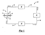
- a sump housing 10 is part of a re-circulating lubrication system 22.
- the sump housing is disposed to scavenge lubricant 12 ejected from a bearing 14 and a shaft 16.
- the shaft 16 and an inner race of the bearing 14 are structures disposed for rotation about an axis 20, in a direction represented by arrow 18.
- the sump housing 10 can scavenge lubricant ejected from some other kind of structure, such as a gear or a seal or any other rotating structure.
- the system 22 can be part of a turbine engine or any other operating environment in which a lubricated structure rotates at relatively high speed.
- the system 22 also includes a reservoir 24, a primary pump 26, a scavenge pump 28, and fluid lines 30, 32, 34, 36 connecting the sump housing 10, the reservoir 24, the primary pump 26, and the scavenge pump 28.
- Lubricant 12 such as oil
- Lubricant 12 is drawn through the fluid line 30 from the reservoir 24 by the primary pump 26.
- Lubricant 12 is directed through the fluid line 32 by the primary pump 26 to the sump housing 10.
- the lubricant 12 is sprayed on the bearing 14 and/or the shaft 16 supported by the bearing 14 by a nozzle 38 (shown in Figure 2 ) disposed in the sump housing 10.
- Lubricant 12 is drained from the sump housing 10 through the fluid line 34 by the scavenge pump 28.
- Lubricant 12 is directed through the fluid line 36 by the scavenge pump 28 to return the lubricant
- the sump housing 10 extends along the axis 20 and includes an outer wall 40 with an inner surface 42 defining a chamber 44.
- the view of Figure 2 is a plane normal to the axis 20.
- the axis 20 is also the longitudinal axis of the sump housing 10 in the first exemplary embodiment.
- Embodiments of the sump housing 10 can have any desired inner radius.
- the lubricated bearing 14 is disposed within the chamber 44.
- the lubricant 12 is expelled from the bearing 14 and collects on the inner surface 42 to a lubricant film height 46.
- the lubricant 12 appears to have a constant film height 46, however, film height 46 may vary at different positions about the axis 20.
- Windage 48 is moving air disposed within the sump housing 10 that is itself urged in motion by rotation of the shaft 16.
- the flow field of the windage 48 is represented by a velocity profile that can be determined by solving standard turbulent flow equations in either closed form or by using commercial CFD software.
- the velocity of the windage 48 at the lubricant film height 46 will be some fraction of the tangential component of the angular velocity of the shaft 16.
- a generalization of a velocity profile defined between the velocity of the air at the shaft 16 and the velocity of the air at the lubricant film height 46 can be referred to as the bulk air flow velocity.
- the bulk air flow velocity is a percentage of the tangential component of the angular velocity of the shaft 16.
- the windage 48 at the lubricant film height 46 will act on the surface of the lubricant 12, urging movement of the lubricant 12 in the rotational direction, as shown by arrows 50, 52, 54.
- the sump housing 10 includes an out-take 56 for lubricant scavenging.
- the out-take 56 extends across a chordal arc 58 (shown in Figure 4 ) of the chamber 14.
- the chordal arc 58 is concentric with and has the same radius as the cylindrical portion of the sump housing 10. In other words, the chordal arc 58 completes the circle that would be defined by the inner surface 42 if the out-take were not present.
- the out-take 56 includes a first portion 60 of the outer wall 40 diverging away from the chordal arc 58 at a first rate.
- the first portion 60 is disposed on the forward or upstream side of the out-take 56.
- the inner surface 42 extends along a path that is concentric to the chordal arc 58 in the lubricant flow direction (the direction of rotation of the shaft 16) until reaching the first portion 60.
- the first rate can be defined as the rate of change in the distance between the inner surface 42 and the axis 20 over a particular angle about the axis 20.
- the exemplary first portion 60 extends from a first end or first upstream point 64 at bottom dead center of the sump housing 10 to a second end or first downstream point 66 spaced from the first upstream point 64 about the axis 20 in the direction of rotation of the shaft 16.
- upstream and downstream refer to flow of moving air in the chamber 44.
- the first upstream point 64 is disposed at bottom dead center.
- the exemplary first downstream point 66 is spaced from bottom dead center in the direction of rotation of the shaft 16.
- the first upstream point 64 may be spaced from bottom dead center and the second end may be spaced any desired distance from the first upstream point 64 in alternative embodiments of the invention. It is also noted that the sump housing 10 can be used in operating environments where the orientation of the sump housing 10 relative to the direction of gravity is not constant, such as aircraft applications.
- the exemplary first rate of divergence results in the shape of the first portion 60 being circular in a plane perpendicular to the axis 20.
- the first rate could be different than the first exemplary embodiment and thereby result in the first portion 60 being a different shape, such as a straight ramp-like shape, a spiral shape, an elliptical shape, any combination of these shapes.
- the first portion 60 is circular and convex relative to the chamber 44 such that a center of the circular profile, represented by a point 68, is disposed on a side the first portion 60 opposite the axis 20.
- the out-take 56 also includes a second portion 62 of the outer wall 40 opposite the first portion 60.
- the downstream second portion 62 is disposed on the aft or downstream side of the out-take 56.
- the second portion 62 diverges away from the chordal arc 58 toward the first portion 60 and a second rate greater than the first rate to define a blunt wall 62 facing the gentle slope of the first portion 60.
- the absolute value of the second rate is greater than the absolute value of the first rate.
- the inner surface 42 extends along a path that is concentric to the chordal arc 58 in a direction opposite to the direction of rotation until reaching the second portion 62.
- the second rate is defined as the first rate is defined, the change in radial distance between the inner surface 42 and the axis 20 over the change in angular position about the axis 20.
- the exemplary second portion 62 extends from a first end or second downstream point 70 to second end or second upstream point 72 spaced from the first end 70 about the axis 20 in the direction opposite to the direction of rotation.
- the first and second ends 70 may be spaced as desired relative to bottom dead center and/or relative the first and second ends 64, 66 of the first portion 60 in alternative embodiments.
- the exemplary second rate results in the shape of the second portion 62 being circular in a plane perpendicular to the axis 20.
- the second rate could be different than the first exemplary embodiment and thereby result in the second portion 62 being a different shape, such as a straight ramp-like shape, a spiral shape, an elliptical shape, any combination of these shapes.
- the second portion 62 is convex relative to the chamber 44.
- the radius of the second portion 62 is greater than the radius of the first portion 60 in the first exemplary embodiment of the invention.
- a minimal round can be defined at the first end 70, between the second portion 62 and the remainder of the outer wall 40, to enhance the flow of lubricant 12 around the first end 70.
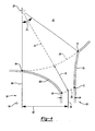
- Figure 5 shows the relative "bluntness" of the wall or second portion 62 in the exemplary embodiment of the invention.
- An imaginary line 108 is shown extending from and/or through the point 64.
- the point 64 is one end of the chordal 58 arc and is also the point along the inner surface 42 (see Figure 2 ) where the first upstream portion 60 begins to diverge away from the circular profile of the sump housing.
- the line 108 is tangent to the chordal arc 58 and to the inner surface 42 at point 64.
- the downstream blunt wall 62 is arranged to be substantially perpendicular to the line 108.
- a line 110 is precisely perpendicular the line 108 and extends through a point 112; the point 112 is the point at which the line 108 intersects the outer surface of the second portion 62.
- a line 114 extends between the first and second ends 70, 72 of the second portion and represents the through point 112 and is tangent to the blunt wall 62 at the point 112.
- the blunt wall 62 is offset an angle 116 from being precisely perpendicular to the line 108 at the point 112.
- the angle 116 can be greater than zero up to about twenty degrees. The smaller the angle of offset, the more likely an air vortex operable to separate air from lubricant will be created.
- the chordal arc 58 of the out-take 56 extends between the respective first ends 64, 70 of the first and second portions 60, 62.
- An angle 74 is defined between the ends of the chordal arc 58.
- the upstream edge of the angle 74 (defined at the first upstream point 64) is disposed at bottom dead center. As a result, the entire range of the angle 74 is downstream of bottom center. In alternative embodiments of the invention, the upstream edge of the angle 74 could be disposed upstream of bottom dead center.
- the out-take 56 defines a depth represented by arrow 76.
- the arrow 76 extends along an axis 78 that intersects the axis 20 of rotation.
- the arrow 76 extends between the choral arc 58 and a secondary arc 80.
- the secondary arc 80 is concentric with the chordal arc 58; both arcs 58 and 80 are centered on the axis 20.
- the secondary arc 80 extends between the respective second ends 66, 72 of the first and second portions 60, 62.
- the depth of the out-take 56 is the distance from the chordal arc 58 to the point where the out-take 56 merges with a drain of substantially constant width (described in greater detail below).
- the out-take 56 merges with a drain portion 82.
- the exemplary drain portion 82 is of substantially constant diameter, represented by arrow 84, and has straight walls in the plane normal to the axis 20.
- the first portion 60 transitions to the drain portion 82 at the first downstream point 66 and the second portion 62 transitions to the drain portion 82 at the second end 72.
- the drain portion 82 extends along a drain axis 86.
- the drain axis 86 is offset from an axis 88 that extends through bottom dead center of the sump housing 10 and the axis 20 of rotation.
- Arrow 90 represents the distance between the axes 86, 88.
- the relative configurations of the first and second portions 60, 62 cooperate during operation such that at least one air vortex 92 is created in the out-take 56.
- This vortex 92 urges lubricant out of the sump housing 10 while concurrently reducing the likelihood that air will exit the sump housing with the lubricant, or will meaningfully compete with the lubricant for scavenge capacity. Competition between lubricant and air over scavenge capacity can occur in sump housings generally.
- the bulk of the lubricant film velocity is a smaller fraction of the tangential component of the angular velocity of the shaft 16 than the bulk air flow velocity of the windage 48. This is generally of no consequence anywhere within the sump housing 10 except where it is necessary to drain the lubricant 12 out of the sump housing 10.
- air associated with windage can compete with the lubricant for space in the drain and for space (or capacity) of a scavenge pump.
- a scavenge pump used to drain a sump housing usually has a fixed capacity.
- the vortex 92 urges lubricant out of the sump housing 10 while concurrently reducing the likelihood that air will exit the sump housing 10 with the lubricant, or will meaningfully compete with the lubricant for scavenge capacity.
- the left side of the vortex 92 is adjacent to the first portion 60 of the out-take 56.
- the left side of the vortex 92 is shown acting generally against the flow of lubricant 12 to the drain portion 82.
- the velocity of the air in the vortex 92 along the first portion 60 is negligible.
- the velocity of moving air in the vortex is approximately maximum and is yet a relatively small percentage of the tangential velocity of windage 48 acting on the lubricant 12 at bottom dead center 64.
- gravity and momentum are relatively more dominant in predicting lubricant flow at point 94 and are therefore more useful in controlling lubricant flow.
- the vortex 92 is disposed adjacent to the second portion 62.
- Figure 2 shows that the right side of the vortex 92 cooperates with momentum in urging lubricant toward the drain portion 82.
- the geometry of the out-take 56 can be varied to enhance the characteristics of the vortex 92, including the depth of the out-take 56 as represented by arrow 76, the angular size of the out-take 56 about the axis 20 as represented by angle 74, the first and second rates of divergence, and the positions of the first and second portions 60, 62 relative to bottom dead center of the sump housing 10.
- FIGS 2 and 3 show that a smaller vortex 96 can also be generated during operation.
- the left side of the vortex 96 is adjacent to the first portion 60 of the out-take 56 and cooperates with gravity in urging lubricant toward the drain portion 82.
- the vortex 96 is disposed adjacent to the second portion 62 and acts generally against the flow of lubricant 12 to the drain portion 82.
- the velocity of the vortex 96 along the second portion 62 is negligible.
- gravity and momentum are relatively more dominant in predicting lubricant flow along the second portion 62 adjacent the vortex 96 and are therefore useful in controlling lubricant flow.
- the vortex 96 circles in a counterclockwise direction and does not meaningfully compete with lubricant for scavenging capacity.
- the sump housing 10 and the inner surface 42, other than the first and second portions 60 and 62, are cylindrical and symmetrical about the axis 20.
- the sump housing 10 can be asymmetrical about the longitudinal axis 18 and need not be cylindrical in a general, overall sense. The fact that the sump housing 10 may or may not be cylindrical at a given axial section does not abrogate the workings of the broader invention.
- the sump housing 10 can house more than one bearing 14 or more than one lubricated component.
- An exemplary sump housing was constructed with an inner radius of about 4.625 inches.
- the first end of the first portion of the out-take was at bottom dead center and the second end of the first portion was spaced about 11.5° away from bottom dead center.
- the first rate of divergence of the first portion resulted in the shape of the first portion being circular with a radius of 0.923 inch in the plane perpendicular to the axis of rotation.
- the first end of the second portion was spaced about 41° from bottom dead center and the second end of the second portion was spaced about 19° from bottom dead center.
- the second rate of divergence resulted in the second portion being circular with a radius of 5.769 inches in the plane perpendicular to the axis of rotation.
- the exemplary angle of the chordal arc was about 41.5°.
- the drain depth was about 1 inch and the drain was offset about 1.5 inches.
- a structure was disposed in the sump housing and rotated at about 5,000 rpm to 15,000 rpm.
- the blunt wall was about 5 - 10 degrees offset from perpendicular.
- the dimensions provided by the example set forth above are for illustration only and are not limiting to the invention.
- the dimensions provided herein can be helpful when considered relative to one another.
- the example may be considered a relatively small embodiment.
- one or more of the dimensions provided herein may be multiplied as desired.
- different operating environments may dictate different relative dimensions.
- the straightness or curvature of the outer surface of the blunt wall 62, the angle or extent of offset from perpendicular of the blunt wall 62, the drain depth, and the drain offset can be varied in view of one another in alternative embodiments of the invention to separate the moving air from the lubricant moving along the inner surface 42.
- Several different geometric arrangements can be applied to practice the invention. Generally, it may be desirable to select a relatively smaller angle of offset from perpendicular in combination with a relatively straight blunt wall 62.
- Figure 6 shows an embodiment of the invention that includes a first portion 60b extending between a point 64b and a first downstream point 66b, a second portion or blunt wall 62b extending between ends 70b and 72b, and a chordal arc 58b extending from the point 64b to the end 70b.
- the blunt wall 62b is flat and precisely perpendicular to a line 108b that is tangent to the chordal arc 58b at the point 64b.
- the drain depth and drain offset can also be varied in view of the desired shape of the blunt wall and vice-versa.
- the blunt wall 62 is configured to separate moving air from lubricant while concurrently not acting like an air scoop.
- the portion of the blunt wall 62 between the end 70 and the point 112 is at least perpendicular to the line 108 or falls away relative to perpendicular.
- the portion of the blunt wall 62 extending from the point 112 to the end 70 extends away from the first portion 60.
- the portion of the blunt wall 62 between the end 70 and the point 112 does not extend in the direction of the first portion 60 and therefore will not act as an air scoop.
- the portion of the blunt wall 62 extending from the point 112 to the second end 72 preferably extends perpendicular to the line 108 or extends toward the first portion 60, at least initially.
- the blunt wall 62 extends gradually toward the first portion 60 from the point 112 to the end 72.
- Figure 7 shows a third alternative embodiment of the invention that includes a first portion 60c extending between a point 64c and a first downstream point 66c, a second portion or blunt wall 62c extending between ends 70c and 72c, and a chordal arc 58c extending from the point 64c to the end 70c.
- the blunt wall 62c is arcuate and is offset from perpendicular over a portion between the end 70c and a point 112c.
- the blunt wall 62c continues in the same general direction past the point 112c, toward the first portion 60c, to a transition point 118c. Between the transition point 118 and the second end 72c, the blunt wall 62c extends away from the first portion 60c.
- the arrangement of the third exemplary embodiment enhances the separation of air from the lubricant.
- Figure 8 shows a second embodiment of the invention.
- a sump housing 10a extends about an axis 20a and includes an outer wall 40a with an inner surface 42a around a chamber 44a.
- An out-take 56a is formed in the housing 10a and includes first and second portions 60a, 62a of the outer wall 40a and extending across a chordal arc 58a.
- the first portion 60a extends between first and second ends 64a and 66a.
- the second portion 62a extends between first and second ends 70a and 72a.
- the second embodiment is different than the first embodiment in several aspects.
- the first portion 60a is partially spiral and partially a circular round in the plane normal to the axis 20a.
- the first portion 60a diverges from the chordal arc initially along a spiral path and then transitions to a circular round before again transitioning to a drain portion 82a.
- the spiral segment of the first portion 60a can be defined by any spiral equation including Archimedean, Equiangular, Fermat, Lituus, Fibonacci, Theodorus, or any combination of these forms of spirals.
- the first portion 60a is concave relative to the chamber 44a.
- the first upstream point 64a of the first portion 60a is disposed upstream of bottom dead center.
- the second embodiment also differs from the first embodiment by including a scavenge scoop 98a.
- a volume bounded by the first portion 60, the second portion 62, and the chordal arc 58 is fully exposed to the chamber 44.
- the relative structures result in the creation of the vortex 92 during operation.
- the scavenge scoop 98a reduces the likelihood that windage will limit lubricant scavenging by shearing or slicing the windage from the lubricant.
- the scavenge scoop 98a is disposed above and cooperates with the first portion 60a to define an intake 100a for receiving lubricant moving along the inner surface 42a.
- the intake 100a has an intake height substantially equal to the height of lubricant to substantially prevent windage from entering the intake 100a.
- the intake height is the distance between the inner surface 42a along the first portion 60a and an upstream edge 102a of the scavenge scoop 98a and is selected to reduce the likelihood of air entering the intake 100a.
- the intake 100a efficiently separates the lubricant from the windage inside the sump housing 10a.
- the exemplary embodiment of the invention uses the surface tension and viscosity of the lubricant to separate the lubricant from the air.
- the scavenge scoop 98a diverts the air flow up and over the intake 100a.
- the lubricant remains attached to the inner surface 42a of the sump housing 10a and the windage does not remain attached to the surface of the lubricant.
- the lubricant will travel along the inner surface 42a and diverge from a circular path (in the plane perpendicular to the axis 20a) at the end 64a to the spiral path of the first portion 60a. After traveling along the spiral path, the lubricant enters the intake 100a below the edge 102a, downstream from the end 64a.
- the dimension of the lubricant film height is responsive to several factors, including but not limited to the viscosity of the lubricant, the density of the lubricant, the surface tension of the lubricant, the rotational speed of the structure rotating in the sump housing 10a, the diameter of the rotating structure, the diameter of the inner surface 42a of the sump housing 10a, and the flow rate of lubricant into the sump housing 10a.
- the velocity of the lubricant film moving along the inner surface 42a is also responsive to these factors. It has been found that the lubricant film height and velocity can be calculated based on these factors in combination with mathematical models developed with computational fluid dynamics software.
- a first physical model can be prepared to evaluate the generation of lubricant droplets from the rotating structure.
- a second physical model can be prepared to evaluate the impact of lubricant droplets against the inner surface 42a.
- a third physical model can be prepared to evaluate fluid behavior around the intake 100a. These computational models can be developed and evaluated to determine the lubricant film height at the intake 100a. An alternative process for determining lubricant film height at the intake 100a would include constructing physical models of the sump housing 10a and testing the models in the field and/or under laboratory conditions. Testing physical models can verify the results of the computational models or can take the place of developing computational models.
- Non-dimensional lubricant film heights of between 8.75897E-02 and 1.00000E+00 have been computed based on ranges of factors that tend to effect lubricant film height.
- the ratio (R2/R1) of the radial distance from the axis 20a to the inner surface 42a (R2) to the radius of the rotating structure (R1) is believed to effect the lubricant film height.
- the ratio (R2/R1) in the computations ranged from 1.3 - 1.5.
- the invention can be practiced in environments wherein the ratio (R2/R1) is outside this range.
- the speed of rotation is believed to effect the lubricant film height.
- the speed of rotation in the computations ranged from 5000 rpm - 25,000 rpm.
- the invention can be practiced in environments wherein the shaft rpm is outside this range.
- the temperature of the lubricant is believed to effect the lubricant film height.
- the temperature of the lubricant in the computations ranged from 50°F - 350°F.
- the invention can be practiced in environments wherein the temperature of the lubricant is outside this range.
- the flow rate of lubricant out of the sump housing is believed to effect the lubricant film height.
- the flow rate of lubricant out of the sump housing in the computations ranged from 0.1 gal/min - 1.0 gal/min.
- the invention can be practiced in environments wherein the flow rate of lubricant out of the sump housing is outside this range.
- the scavenge scoop 98a is positioned above the inner surface 42a a height substantially equal to the lubricant film height to reduce the likelihood of air entering the intake 100a.
- the scavenge scoop 98a may be positioned slightly higher than a theoretical or calculated lubricant film height. For example, waves may be generated on the surface of the lubricant film 12 in some operating environments, resulting in a slightly variable lubricant film height. In some of these operating environments, by way of example and not limitation, waves on the surface of the lubricant film could be approximately 10% of the film height.
- the position of the scavenge scoop 98a relative to the inner surface 42a can be determined based on the expected presence of surface waves on the surface of the lubricant film.
- the exemplary scavenge scoop 98a extends away from the edge 102a along the chordal arc 58a with a windage deflecting or guiding surface 104a.
- the surface 104a extends away from the edge 102a about the axis 20a in the rotational direction and can limit turbulence associated with interaction between the windage and the edge 102a. Windage can be directed across the intake 100a along the deflecting surface 104a around the axis 20a without substantial disturbance in flow.
- the downstream side of the scavenge scoop 98a, opposite the edge 102a, can cooperate with the second portion 62a to define an opening for receiving lubricant flowing clockwise around the axis 20a.
- the scavenge scoop 98a can also include one or more perforations 106a, or through apertures, to increase the likelihood that lubricant will drain from the sump housing 10a.
- the lubricant that may accumulate on the surface 104a can drain from the sump housing 10a through the perforations 106a.
Landscapes
- Engineering & Computer Science (AREA)
- Mechanical Engineering (AREA)
- General Engineering & Computer Science (AREA)
- Rolling Contact Bearings (AREA)
- General Details Of Gearings (AREA)
Claims (13)
- Sumpfgehäuse (10, 10a) für eine geschmierte Struktur (14, 16), die sich mit verhältnismäßig hoher Geschwindigkeit dreht, das Folgendes umfasst:eine Außenwand (40, 40a), die eine Innenfläche (42) einschließt, die eine Kammer (44, 44a) definiert und einen zylindrischen Abschnitt hat, undeinen Abzug (56, 56a) zum Spülen von Schmiermittel (12) durch das Trennen von Luft, die sich in dem Sumpfgehäuse bewegt, von dem Schmiermittel (12), wobei sich der Abzug (56, 56a) von einem Sehnenbogen (58, 58a, 58b, 58c) des zylindrischen Abschnitts der Außenwand (40, 40a) aus nach außen erstreckt und wobei der Abzug (56, 56a) einen stromaufwärts gelegenen ersten Abschnitt (60, 60a, 60b) der Außenwand, der sich mit einer ersten Rate von der Außenwand (40, 40a) nach außen entfernt, einschließt, der sich von einem ersten stromaufwärts gelegenen Punkt (64, 64a, 64b, 64c) an dem zylindrischen Abschnitt der Außenwand (40, 40a) zu einem ersten stromabwärts gelegenen Punkt (66, 66a, 66b, 66c) erstreckt, wobei der Abzug (56, 56a) ebenfalls einen stromabwärts gelegenen zweiten Abschnitt (62, 62a, 62b, 62c) der Außenwand (40, 40a) gegenüber dem ersten Abschnitt (60, 60a, 60b), der sich mit einer zweiten Rate, die größer ist als die erste Rate, von der Außenwand (40, 40a) nach außen und zu dem ersten Abschnitt (60, 60a, 60b) hin entfernt, einschließt, wobei sich der zweite Abschnitt (62, 62a, 62b, 62c) von einem ersten Ende (70) an dem zylindrischen Abschnitt der Außenwand (40, 40a) zu einem zweiten Ende (72, 72b, 72c) erstreckt, wobei der erste stromabwärts gelegene Punkt (66, 66a, 66b, 66c) und das zweite Ende (72, 72b, 72c) auf einem sekundären Bogen (80), konzentrisch mit dem Sehnenbogen (58, 58a, 58b, 58c), angeordnet sind,dadurch gekennzeichnet, dassder stromabwärts gelegene zweite Abschnitt (62, 62a, 62b, 62c) eine Wand (62, 62a, 62b, 62c) ist, die 0 bis 20 Grad gegenüber der Senkrechten zu einer Linie (108, 108b) versetzt ist, die Tangente zu dem Sehnenbogen (58, 58a, 58b, 58c) in dem ersten stromaufwärts gelegenen Punkt (64, 64a, 64b, 64c) an der Überschneidung (112) der Wand (62, 62a, 62b, 62c) mit der Linie (108, 108b) ist, wobei die Wand (62, 62a, 62b, 62c) zu dem ersten Abschnitt (60, 60a, 60b) zeigt, um Luft zu begrenzen, die aus dem Sumpfgehäuse (10, 10a) durch den Abzug (56, 56a) austritt, undder stromaufwärts gelegene erste Abschnitt (60, 60a, 60b) und der stromabwärts gelegene zweite Abschnitt (62, 62a, 62b, 62c) derart zusammenwirken, dass während des Betriebs wenigstens ein Luftwirbel (92) in dem Abzug (56, 56a) gebildet wird, um Schmiermittel (12) aus dem Sumpfgehäuse (10) zu drängen, während gleichzeitig die Wahrscheinlichkeit verringert wird, dass Luft mit dem Schmiermittel (12) aus dem Sumpfgehäuse (10) austreten wird.
- Sumpfgehäuse (10, 10a) nach Anspruch 1, wobei der erste stromaufwärts gelegene Punkt (64, 64a, 64b, 64c) an einer unteren Totpunktposition des Sumpfgehäuses (10, 10a) angeordnet ist.
- Sumpfgehäuse (10, 10a) nach Anspruch 1, wobei sich der Sehnenbogen (58, 58a, 58b, 58c) zwischen einem ersten Ende (64, 64a, 64b, 64c) des ersten Abschnitts (60, 60a, 60b) und einem ersten Ende (70, 70a, 70b, 70c) des zweiten Abschnitts (62, 62a, 62b, 62c) erstreckt und wobei das erste Ende (70, 70a, 70b, 70c) des zweiten Abschnitts (62, 62a, 62b, 62c) weiter von einem unteren Totpunkt des Sumpfgehäuses (10, 10a) beabstandet ist als das erste Ende (64, 64a, 64b, 64c) des ersten Abschnitts (60, 60a, 60b), so dass der Abzug (56, 56a) winklig aus dem unteren Totpunkt verschoben ist.
- Sumpfgehäuse (10, 10a) nach Anspruch 1, wobei der erste Abschnitt (60, 60a, 60b) ferner als bogenförmig in einem Querschnitt definiert ist.
- Sumpfgehäuse (10, 10a) nach Anspruch 1, wobei der erste Abschnitt (60, 60a, 60b) ferner so definiert ist, dass er konvex im Verhältnis zu der Kammer (44, 44a) ist.
- Sumpfgehäuse (10, 10a) nach Anspruch 1, das ferner Folgendes umfasst:einen Ablaufabschnitt (82), der funktionsfähig ist, um Schmiermittel (12) aus dem Abzug (56, 56a) aufzunehmen, wobei sich der Ablaufabschnitt (82) entlang einer Achse (86) erstreckt, die geradlinig von einer Mittelachse (20) des Sumpfgehäuses (10, 10a) versetzt ist.
- Sumpfgehäuse (10) nach Anspruch 1, wobei ein durch den ersten Abschnitt (60, 60b) und den zweiten Abschnitt (62, 62b, 62c) und den Sehnenbogen (58, 58b, 58c) begrenztes Volumen vollständig zu der Kammer (44) freigelegt ist.
- Sumpfgehäuse (10a) nach Anspruch 1, das ferner Folgendes umfasst:eine Abzugsschaufel (98a), die oberhalb des ersten Abschnitts (60a) angeordnet ist und mit demselben zusammenwirkt, um einen Einlass (100a) zum Aufnehmen von Schmiermittel (12), das sich entlang einer Innenfläche (42) der Außenwand (40a) bewegt und eine Filmhöhe im Verhältnis zu der Innenfläche (42) definiert, wobei der Einlass (100a) eine Einlasshöhe hat, die im Wesentlichen gleich der Filmhöhe des Schmiermittels (12) ist, um zu verhindern, dass sich bewegende Luft in den Einlass (100a) eintritt.
- Sumpfgehäuse (10a) nach Anspruch 8, wobei die Abzugsschaufel (98a) ferner Folgendes umfasst:eine Luftströmung-Ablenkungsfläche (104a), die sich entlang des Sehnenbogens (58a) erstreckt, um Turbulenz, die mit der Wechselwirkung zwischen der sich bewegenden Luft und dem Einlass (100a) verbunden ist, zu begrenzen.
- Sumpfgehäuse (10a) nach Anspruch 1, wobei der zweite Abschnitt (62c) ferner so definiert wird, dass er sich teilweise zu dem ersten Abschnitt hin erstreckt und sich teilweise von dem ersten Abschnitt weg erstreckt.
- Sumpfgehäuse (10, 10a) nach Anspruch 1, wobei der erste Abschnitt (60, 60b) ferner als kreisförmig im Querschnitt in einer Ebene, senkrecht zu einer Mittelachse (20) des Sumpfgehäuses (10, 10a), mit einem ersten Radius definiert wird und der zweite Abschnitt (62, 62b) ferner als kreisförmig im Querschnitt in der Ebene mit einem zweiten Radius, der wenigstens das doppelte des ersten Radius beträgt, definiert wird.
- Sumpfgehäuse (10, 10a) nach Anspruch 8, wobei die Abzugsschaufel (98a) ferner Folgendes umfasst:eine Ablenkungsfläche (104a), konkav zu einer Mittelachse (20) des Sumpfgehäuses (10, 10a) und sich von dem Einlass (100a) weg in der Winkeldrehrichtung der Struktur (14, 16) erstreckend.
- Turbinentriebwerk, das Folgendes umfasst:eine Struktur (14, 16), die zur Drehung um eine Achse (20) angeordnet ist,eine Schmieranlage (22), die funktionsfähig ist, um Schmiermittel (12) zu der Struktur (14, 16) zu leiten,ein Sumpfgehäuse (10, 10a) nach einem der Ansprüche 1 bis 12.
Applications Claiming Priority (3)
| Application Number | Priority Date | Filing Date | Title |
|---|---|---|---|
| US86567906P | 2006-11-14 | 2006-11-14 | |
| US86568006P | 2006-11-14 | 2006-11-14 | |
| US11/939,071 US7789200B2 (en) | 2006-11-14 | 2007-11-13 | Sump housing |
Publications (3)
| Publication Number | Publication Date |
|---|---|
| EP1923540A2 EP1923540A2 (de) | 2008-05-21 |
| EP1923540A3 EP1923540A3 (de) | 2011-01-12 |
| EP1923540B1 true EP1923540B1 (de) | 2015-11-11 |
Family
ID=39020966
Family Applications (1)
| Application Number | Title | Priority Date | Filing Date |
|---|---|---|---|
| EP07022137.9A Active EP1923540B1 (de) | 2006-11-14 | 2007-11-14 | Ölsumpfgehäuse |
Country Status (2)
| Country | Link |
|---|---|
| US (1) | US7789200B2 (de) |
| EP (1) | EP1923540B1 (de) |
Cited By (1)
| Publication number | Priority date | Publication date | Assignee | Title |
|---|---|---|---|---|
| EP4382776B1 (de) * | 2022-12-09 | 2025-10-01 | Safran Transmission Systems | Schmierölrückgewinnungsrinne für reduktionsgetriebe mit verbessertem deflektor |
Families Citing this family (14)
| Publication number | Priority date | Publication date | Assignee | Title |
|---|---|---|---|---|
| GB0816562D0 (en) * | 2008-09-11 | 2008-10-15 | Rolls Royce Plc | Lubricant scavenge arrangement |
| RU2416034C1 (ru) * | 2009-09-23 | 2011-04-10 | Открытое акционерное общество "Научно-производственное объединение "Сатурн" (ОАО "НПО "Сатурн") | Устройство для отвода масла из опоры ротора турбомашины |
| US9404381B2 (en) | 2012-09-04 | 2016-08-02 | United Technologies Corporation | Turbine engine transmission gutter |
| US9695714B2 (en) | 2013-04-22 | 2017-07-04 | United Technologies Corporation | Low loss bearing drain |
| US9759094B2 (en) * | 2015-06-24 | 2017-09-12 | General Electric Company | Pump for a turbine engine |
| US9853523B2 (en) | 2015-08-29 | 2017-12-26 | Fairfield Manufacturing Company, Inc. | Wheel motor cooling system with equally divided flow |
| FR3084407B1 (fr) | 2018-07-26 | 2021-04-30 | Safran Aircraft Engines | Gouttiere de canalisation d'huile de lubrification d'une turbomachine d'aeronef |
| US11286854B2 (en) | 2019-08-08 | 2022-03-29 | Raytheon Technologies Corporation | Ducted oil scoop for gas turbine engine |
| US11162421B2 (en) * | 2019-10-22 | 2021-11-02 | Pratt & Whitney Canada Corp. | Bearing cavity and method of evacuating oil therefrom |
| US11970972B2 (en) * | 2019-10-23 | 2024-04-30 | Rtx Corporation | Windage blocker for oil routing |
| US11719127B2 (en) | 2019-10-23 | 2023-08-08 | Raytheon Technologies Corporation | Oil drainback assembly for a bearing compartment of a gas turbine engine |
| US11939070B2 (en) | 2020-02-21 | 2024-03-26 | General Electric Company | Engine-mounting links that have an adjustable inclination angle |
| US11970279B2 (en) | 2020-02-21 | 2024-04-30 | General Electric Company | Control system and methods of controlling an engine-mounting link system |
| US20250369509A1 (en) * | 2024-06-04 | 2025-12-04 | Pratt & Whitney Canada Corp. | Combined rotating component and fluid port baffle |
Citations (1)
| Publication number | Priority date | Publication date | Assignee | Title |
|---|---|---|---|---|
| GB191500638A (en) * | 1915-01-15 | 1915-09-23 | Albion Motor Car Co Ltd | Improvements in Oil-returning Devices for Bearings. |
Family Cites Families (41)
| Publication number | Priority date | Publication date | Assignee | Title |
|---|---|---|---|---|
| GB1050391A (de) | ||||
| US2650671A (en) * | 1952-09-25 | 1953-09-01 | Gen Electric | Oil discharge passage arrangement for high-speed bearings |
| CH393003A (de) | 1962-04-13 | 1965-05-31 | Oerlikon Maschf | Horizontales Gleitlager |
| GB1129419A (en) | 1967-07-17 | 1968-10-02 | Rolls Royce | Gas turbine engine |
| GB1217807A (en) | 1969-07-19 | 1970-12-31 | Rolls Royce | Gas turbine engine |
| GB2043799B (en) | 1979-03-05 | 1983-03-16 | Rolls Royce | Draining oil from bearing |
| DE3048101A1 (de) | 1979-12-21 | 1981-09-10 | Rolls-Royce Ltd., London | "vorrichtung zum aufbereiten von stroemungsmitteln" |
| DE3137947C2 (de) | 1980-09-26 | 1983-10-27 | Rolls-Royce Ltd., London | Für beliebige Flugmanöver taugliches Schmierölsystem für Gasturbinentriebwerke |
| US4339160A (en) | 1981-01-12 | 1982-07-13 | Mchugh James D | Sealing arrangement for hot bearing housings |
| GB2135740B (en) | 1983-02-11 | 1986-02-12 | Rolls Royce | Gas turbine engine lubrication systems |
| US4525995A (en) | 1983-04-04 | 1985-07-02 | Williams International Corporation | Oil scavening system for gas turbine engine |
| US4599979A (en) | 1984-08-09 | 1986-07-15 | Outboard Marine Corporation | Upper crankshaft bearing lubrication system for two-cycle engine |
| US4756664A (en) | 1985-10-03 | 1988-07-12 | Sundstrand Corporation | Scavenge oil system |
| US4683984A (en) | 1985-10-03 | 1987-08-04 | Sundstrand Corporation | Scavenge oil system |
| US4683389A (en) | 1985-12-23 | 1987-07-28 | Sundstrand Corporation | Oil scavenge system |
| US4683714A (en) | 1986-06-17 | 1987-08-04 | General Motors Corporation | Oil scavenge system |
| DE3705607A1 (de) * | 1987-02-21 | 1988-09-01 | Porsche Ag | Lagerung eines achsantrieb-kegelritzels |
| US4858427A (en) | 1988-08-08 | 1989-08-22 | General Motors Corporation | Secondary oil system for gas turbine engine |
| FR2658577A1 (fr) | 1990-02-20 | 1991-08-23 | Aerospatiale | Dispositif de lubrification de secours pour reducteur notamment pour boite de transmission principale de giravion. |
| DE4041389A1 (de) | 1990-12-21 | 1992-06-25 | Kugelfischer G Schaefer & Co | Vorrichtung zum entfernen von oel aus ringraeumen |
| US5106209A (en) | 1991-08-07 | 1992-04-21 | General Electric Company | Multi-plane lubricated bearing assembly |
| US5183342A (en) | 1991-12-16 | 1993-02-02 | General Electric Company | Lubricated bearing assembly |
| DE59302524D1 (de) * | 1992-07-07 | 1996-06-13 | Siemens Ag | Einrichtung zur abführung von schmiermittel aus einer lageranordnung |
| GB9220991D0 (en) | 1992-10-06 | 1992-11-18 | Dowty Defence | Lubrication system |
| US5489190A (en) | 1994-07-29 | 1996-02-06 | Alliedsignal Inc. | Dynamic oil scavenge system |
| US5813214A (en) | 1997-01-03 | 1998-09-29 | General Electric Company | Bearing lubrication configuration in a turbine engine |
| US6623238B2 (en) | 1998-08-21 | 2003-09-23 | Honeywell International, Inc. | Air turbine starter with seal assembly |
| US6330790B1 (en) | 1999-10-27 | 2001-12-18 | Alliedsignal, Inc. | Oil sump buffer seal |
| DE19956919A1 (de) | 1999-11-26 | 2001-05-31 | Rolls Royce Deutschland | Gasturbinen-Triebwerk mit einer Lagerkammer |
| US6438938B1 (en) | 2000-11-28 | 2002-08-27 | Rolls-Royce Corporation | Bearing compartment self cooling vent system |
| US6634459B1 (en) * | 2001-08-10 | 2003-10-21 | Caterpillar Inc | Accessory drive and particle trap |
| US6682222B2 (en) | 2001-08-22 | 2004-01-27 | General Electric Company | Bi-directional oil scoop for bearing lubrication |
| GB0218849D0 (en) | 2002-08-14 | 2002-09-25 | Rolls Royce Plc | Lubrication system for gas turbine engine |
| JP3843333B2 (ja) | 2002-09-11 | 2006-11-08 | 株式会社日立製作所 | スクロール流体機械 |
| US6672102B1 (en) | 2002-11-27 | 2004-01-06 | Carrier Corporation | Oil recovery and lubrication system for screw compressor refrigeration machine |
| GB0300183D0 (en) | 2003-01-06 | 2003-02-05 | Waterworth Anthony | Feed and scavenge pump arrangement |
| US6996968B2 (en) | 2003-12-17 | 2006-02-14 | United Technologies Corporation | Bifurcated oil scavenge system for a gas turbine engine |
| ITTO20031045A1 (it) * | 2003-12-24 | 2005-06-25 | Fiat Ricerche | Combustore rotativo, e generatore elettrico comprendente un tale combustore. |
| US7426834B2 (en) | 2004-02-03 | 2008-09-23 | General Electric Company | “Get home” oil supply and scavenge system |
| GB0414235D0 (en) | 2004-06-25 | 2004-07-28 | Rolls Royce Plc | A lubrication arrangement |
| GB0414619D0 (en) | 2004-06-30 | 2004-08-04 | Rolls Royce Plc | A bearing housing |
-
2007
- 2007-11-13 US US11/939,071 patent/US7789200B2/en active Active
- 2007-11-14 EP EP07022137.9A patent/EP1923540B1/de active Active
Patent Citations (1)
| Publication number | Priority date | Publication date | Assignee | Title |
|---|---|---|---|---|
| GB191500638A (en) * | 1915-01-15 | 1915-09-23 | Albion Motor Car Co Ltd | Improvements in Oil-returning Devices for Bearings. |
Cited By (1)
| Publication number | Priority date | Publication date | Assignee | Title |
|---|---|---|---|---|
| EP4382776B1 (de) * | 2022-12-09 | 2025-10-01 | Safran Transmission Systems | Schmierölrückgewinnungsrinne für reduktionsgetriebe mit verbessertem deflektor |
Also Published As
| Publication number | Publication date |
|---|---|
| EP1923540A2 (de) | 2008-05-21 |
| EP1923540A3 (de) | 2011-01-12 |
| US7789200B2 (en) | 2010-09-07 |
| US20080110813A1 (en) | 2008-05-15 |
Similar Documents
| Publication | Publication Date | Title |
|---|---|---|
| EP1923540B1 (de) | Ölsumpfgehäuse | |
| US8511057B2 (en) | Lubricant scavenge arrangement | |
| US8464835B2 (en) | Lubricant scoop | |
| US8092093B2 (en) | Dynamic impeller oil seal | |
| US8979383B2 (en) | Dynamically-lubricated bearing and method of dynamically lubricating a bearing | |
| JP6540819B2 (ja) | 軸受構造、および、過給機 | |
| US8727628B2 (en) | Dual mode scavenge scoop | |
| US7244096B2 (en) | Curved blade oil scoop | |
| US12473849B2 (en) | Breather shaft | |
| US20180156269A1 (en) | Bearing structure and turbocharger | |
| US20190153895A1 (en) | Bearing structure and turbocharger | |
| CN107110424A (zh) | 涡轮机设备的润滑油收集帽 | |
| JP6593516B2 (ja) | 軸受構造、および、過給機 | |
| US9033108B2 (en) | Lubricant flow suppressor | |
| US20240102550A1 (en) | Lubrication assembly with a lubricant conveyor | |
| US11891996B2 (en) | Compressor element with improved oil injector | |
| KR102856869B1 (ko) | 슬라이딩 베어링 | |
| US20230160321A1 (en) | Bearing and turbocharger | |
| EP2652321B1 (de) | Ein zahnradsystem für eine windturbine | |
| US7399155B2 (en) | Fluid flow guide element and fluid flow apparatus equipped therewith |
Legal Events
| Date | Code | Title | Description |
|---|---|---|---|
| PUAI | Public reference made under article 153(3) epc to a published international application that has entered the european phase |
Free format text: ORIGINAL CODE: 0009012 |
|
| AK | Designated contracting states |
Kind code of ref document: A2 Designated state(s): AT BE BG CH CY CZ DE DK EE ES FI FR GB GR HU IE IS IT LI LT LU LV MC MT NL PL PT RO SE SI SK TR |
|
| AX | Request for extension of the european patent |
Extension state: AL BA HR MK RS |
|
| PUAL | Search report despatched |
Free format text: ORIGINAL CODE: 0009013 |
|
| AK | Designated contracting states |
Kind code of ref document: A3 Designated state(s): AT BE BG CH CY CZ DE DK EE ES FI FR GB GR HU IE IS IT LI LT LU LV MC MT NL PL PT RO SE SI SK TR |
|
| AX | Request for extension of the european patent |
Extension state: AL BA HR MK RS |
|
| 17P | Request for examination filed |
Effective date: 20110303 |
|
| 17Q | First examination report despatched |
Effective date: 20110530 |
|
| AKX | Designation fees paid |
Designated state(s): AT BE BG CH CY CZ DE DK EE ES FI FR GB GR HU IE IS IT LI LT LU LV MC MT NL PL PT RO SE SI SK TR |
|
| REG | Reference to a national code |
Ref country code: DE Ref legal event code: R079 Ref document number: 602007043830 Country of ref document: DE Free format text: PREVIOUS MAIN CLASS: F01D0025180000 Ipc: F01D0025200000 |
|
| GRAP | Despatch of communication of intention to grant a patent |
Free format text: ORIGINAL CODE: EPIDOSNIGR1 |
|
| RIC1 | Information provided on ipc code assigned before grant |
Ipc: F01D 25/20 20060101AFI20150605BHEP |
|
| INTG | Intention to grant announced |
Effective date: 20150707 |
|
| GRAS | Grant fee paid |
Free format text: ORIGINAL CODE: EPIDOSNIGR3 |
|
| GRAA | (expected) grant |
Free format text: ORIGINAL CODE: 0009210 |
|
| AK | Designated contracting states |
Kind code of ref document: B1 Designated state(s): AT BE BG CH CY CZ DE DK EE ES FI FR GB GR HU IE IS IT LI LT LU LV MC MT NL PL PT RO SE SI SK TR |
|
| REG | Reference to a national code |
Ref country code: GB Ref legal event code: FG4D |
|
| REG | Reference to a national code |
Ref country code: CH Ref legal event code: EP |
|
| REG | Reference to a national code |
Ref country code: IE Ref legal event code: FG4D |
|
| REG | Reference to a national code |
Ref country code: AT Ref legal event code: REF Ref document number: 760576 Country of ref document: AT Kind code of ref document: T Effective date: 20151215 |
|
| REG | Reference to a national code |
Ref country code: FR Ref legal event code: PLFP Year of fee payment: 9 |
|
| REG | Reference to a national code |
Ref country code: DE Ref legal event code: R096 Ref document number: 602007043830 Country of ref document: DE |
|
| REG | Reference to a national code |
Ref country code: LT Ref legal event code: MG4D |
|
| REG | Reference to a national code |
Ref country code: NL Ref legal event code: MP Effective date: 20160211 |
|
| REG | Reference to a national code |
Ref country code: AT Ref legal event code: MK05 Ref document number: 760576 Country of ref document: AT Kind code of ref document: T Effective date: 20151111 |
|
| PG25 | Lapsed in a contracting state [announced via postgrant information from national office to epo] |
Ref country code: IT Free format text: LAPSE BECAUSE OF FAILURE TO SUBMIT A TRANSLATION OF THE DESCRIPTION OR TO PAY THE FEE WITHIN THE PRESCRIBED TIME-LIMIT Effective date: 20151111 Ref country code: IS Free format text: LAPSE BECAUSE OF FAILURE TO SUBMIT A TRANSLATION OF THE DESCRIPTION OR TO PAY THE FEE WITHIN THE PRESCRIBED TIME-LIMIT Effective date: 20160311 Ref country code: NL Free format text: LAPSE BECAUSE OF FAILURE TO SUBMIT A TRANSLATION OF THE DESCRIPTION OR TO PAY THE FEE WITHIN THE PRESCRIBED TIME-LIMIT Effective date: 20151111 Ref country code: LT Free format text: LAPSE BECAUSE OF FAILURE TO SUBMIT A TRANSLATION OF THE DESCRIPTION OR TO PAY THE FEE WITHIN THE PRESCRIBED TIME-LIMIT Effective date: 20151111 Ref country code: ES Free format text: LAPSE BECAUSE OF FAILURE TO SUBMIT A TRANSLATION OF THE DESCRIPTION OR TO PAY THE FEE WITHIN THE PRESCRIBED TIME-LIMIT Effective date: 20151111 |
|
| PG25 | Lapsed in a contracting state [announced via postgrant information from national office to epo] |
Ref country code: PT Free format text: LAPSE BECAUSE OF FAILURE TO SUBMIT A TRANSLATION OF THE DESCRIPTION OR TO PAY THE FEE WITHIN THE PRESCRIBED TIME-LIMIT Effective date: 20160311 Ref country code: GR Free format text: LAPSE BECAUSE OF FAILURE TO SUBMIT A TRANSLATION OF THE DESCRIPTION OR TO PAY THE FEE WITHIN THE PRESCRIBED TIME-LIMIT Effective date: 20160212 Ref country code: PL Free format text: LAPSE BECAUSE OF FAILURE TO SUBMIT A TRANSLATION OF THE DESCRIPTION OR TO PAY THE FEE WITHIN THE PRESCRIBED TIME-LIMIT Effective date: 20151111 Ref country code: LV Free format text: LAPSE BECAUSE OF FAILURE TO SUBMIT A TRANSLATION OF THE DESCRIPTION OR TO PAY THE FEE WITHIN THE PRESCRIBED TIME-LIMIT Effective date: 20151111 Ref country code: FI Free format text: LAPSE BECAUSE OF FAILURE TO SUBMIT A TRANSLATION OF THE DESCRIPTION OR TO PAY THE FEE WITHIN THE PRESCRIBED TIME-LIMIT Effective date: 20151111 Ref country code: BE Free format text: LAPSE BECAUSE OF NON-PAYMENT OF DUE FEES Effective date: 20151130 Ref country code: SE Free format text: LAPSE BECAUSE OF FAILURE TO SUBMIT A TRANSLATION OF THE DESCRIPTION OR TO PAY THE FEE WITHIN THE PRESCRIBED TIME-LIMIT Effective date: 20151111 Ref country code: AT Free format text: LAPSE BECAUSE OF FAILURE TO SUBMIT A TRANSLATION OF THE DESCRIPTION OR TO PAY THE FEE WITHIN THE PRESCRIBED TIME-LIMIT Effective date: 20151111 |
|
| REG | Reference to a national code |
Ref country code: CH Ref legal event code: PL |
|
| PG25 | Lapsed in a contracting state [announced via postgrant information from national office to epo] |
Ref country code: CZ Free format text: LAPSE BECAUSE OF FAILURE TO SUBMIT A TRANSLATION OF THE DESCRIPTION OR TO PAY THE FEE WITHIN THE PRESCRIBED TIME-LIMIT Effective date: 20151111 Ref country code: CH Free format text: LAPSE BECAUSE OF NON-PAYMENT OF DUE FEES Effective date: 20151130 Ref country code: LI Free format text: LAPSE BECAUSE OF NON-PAYMENT OF DUE FEES Effective date: 20151130 |
|
| REG | Reference to a national code |
Ref country code: DE Ref legal event code: R097 Ref document number: 602007043830 Country of ref document: DE |
|
| REG | Reference to a national code |
Ref country code: IE Ref legal event code: MM4A |
|
| PG25 | Lapsed in a contracting state [announced via postgrant information from national office to epo] |
Ref country code: EE Free format text: LAPSE BECAUSE OF FAILURE TO SUBMIT A TRANSLATION OF THE DESCRIPTION OR TO PAY THE FEE WITHIN THE PRESCRIBED TIME-LIMIT Effective date: 20151111 Ref country code: SK Free format text: LAPSE BECAUSE OF FAILURE TO SUBMIT A TRANSLATION OF THE DESCRIPTION OR TO PAY THE FEE WITHIN THE PRESCRIBED TIME-LIMIT Effective date: 20151111 Ref country code: RO Free format text: LAPSE BECAUSE OF FAILURE TO SUBMIT A TRANSLATION OF THE DESCRIPTION OR TO PAY THE FEE WITHIN THE PRESCRIBED TIME-LIMIT Effective date: 20151111 Ref country code: DK Free format text: LAPSE BECAUSE OF FAILURE TO SUBMIT A TRANSLATION OF THE DESCRIPTION OR TO PAY THE FEE WITHIN THE PRESCRIBED TIME-LIMIT Effective date: 20151111 |
|
| PLBE | No opposition filed within time limit |
Free format text: ORIGINAL CODE: 0009261 |
|
| STAA | Information on the status of an ep patent application or granted ep patent |
Free format text: STATUS: NO OPPOSITION FILED WITHIN TIME LIMIT |
|
| PG25 | Lapsed in a contracting state [announced via postgrant information from national office to epo] |
Ref country code: MC Free format text: LAPSE BECAUSE OF FAILURE TO SUBMIT A TRANSLATION OF THE DESCRIPTION OR TO PAY THE FEE WITHIN THE PRESCRIBED TIME-LIMIT Effective date: 20151111 |
|
| 26N | No opposition filed |
Effective date: 20160812 |
|
| GBPC | Gb: european patent ceased through non-payment of renewal fee |
Effective date: 20160211 |
|
| PG25 | Lapsed in a contracting state [announced via postgrant information from national office to epo] |
Ref country code: IE Free format text: LAPSE BECAUSE OF NON-PAYMENT OF DUE FEES Effective date: 20151114 |
|
| REG | Reference to a national code |
Ref country code: FR Ref legal event code: PLFP Year of fee payment: 10 |
|
| PG25 | Lapsed in a contracting state [announced via postgrant information from national office to epo] |
Ref country code: SI Free format text: LAPSE BECAUSE OF FAILURE TO SUBMIT A TRANSLATION OF THE DESCRIPTION OR TO PAY THE FEE WITHIN THE PRESCRIBED TIME-LIMIT Effective date: 20151111 |
|
| PG25 | Lapsed in a contracting state [announced via postgrant information from national office to epo] |
Ref country code: BE Free format text: LAPSE BECAUSE OF FAILURE TO SUBMIT A TRANSLATION OF THE DESCRIPTION OR TO PAY THE FEE WITHIN THE PRESCRIBED TIME-LIMIT Effective date: 20151111 |
|
| PG25 | Lapsed in a contracting state [announced via postgrant information from national office to epo] |
Ref country code: GB Free format text: LAPSE BECAUSE OF NON-PAYMENT OF DUE FEES Effective date: 20160211 |
|
| PG25 | Lapsed in a contracting state [announced via postgrant information from national office to epo] |
Ref country code: BG Free format text: LAPSE BECAUSE OF FAILURE TO SUBMIT A TRANSLATION OF THE DESCRIPTION OR TO PAY THE FEE WITHIN THE PRESCRIBED TIME-LIMIT Effective date: 20151111 Ref country code: HU Free format text: LAPSE BECAUSE OF FAILURE TO SUBMIT A TRANSLATION OF THE DESCRIPTION OR TO PAY THE FEE WITHIN THE PRESCRIBED TIME-LIMIT; INVALID AB INITIO Effective date: 20071114 |
|
| PG25 | Lapsed in a contracting state [announced via postgrant information from national office to epo] |
Ref country code: CY Free format text: LAPSE BECAUSE OF FAILURE TO SUBMIT A TRANSLATION OF THE DESCRIPTION OR TO PAY THE FEE WITHIN THE PRESCRIBED TIME-LIMIT Effective date: 20151111 |
|
| PG25 | Lapsed in a contracting state [announced via postgrant information from national office to epo] |
Ref country code: MT Free format text: LAPSE BECAUSE OF FAILURE TO SUBMIT A TRANSLATION OF THE DESCRIPTION OR TO PAY THE FEE WITHIN THE PRESCRIBED TIME-LIMIT Effective date: 20151111 Ref country code: TR Free format text: LAPSE BECAUSE OF FAILURE TO SUBMIT A TRANSLATION OF THE DESCRIPTION OR TO PAY THE FEE WITHIN THE PRESCRIBED TIME-LIMIT Effective date: 20151111 |
|
| REG | Reference to a national code |
Ref country code: FR Ref legal event code: PLFP Year of fee payment: 11 |
|
| PG25 | Lapsed in a contracting state [announced via postgrant information from national office to epo] |
Ref country code: LU Free format text: LAPSE BECAUSE OF NON-PAYMENT OF DUE FEES Effective date: 20151114 |
|
| P01 | Opt-out of the competence of the unified patent court (upc) registered |
Effective date: 20230528 |
|
| PGFP | Annual fee paid to national office [announced via postgrant information from national office to epo] |
Ref country code: DE Payment date: 20241128 Year of fee payment: 18 |
|
| PGFP | Annual fee paid to national office [announced via postgrant information from national office to epo] |
Ref country code: FR Payment date: 20241126 Year of fee payment: 18 |