EP1923160A2 - Bohrwerkzeug mit Hartstoffkopf - Google Patents
Bohrwerkzeug mit Hartstoffkopf Download PDFInfo
- Publication number
- EP1923160A2 EP1923160A2 EP07021806A EP07021806A EP1923160A2 EP 1923160 A2 EP1923160 A2 EP 1923160A2 EP 07021806 A EP07021806 A EP 07021806A EP 07021806 A EP07021806 A EP 07021806A EP 1923160 A2 EP1923160 A2 EP 1923160A2
- Authority
- EP
- European Patent Office
- Prior art keywords
- cutting edges
- main cutting
- drilling tool
- tool according
- edge
- Prior art date
- Legal status (The legal status is an assumption and is not a legal conclusion. Google has not performed a legal analysis and makes no representation as to the accuracy of the status listed.)
- Granted
Links
Images
Classifications
-
- B—PERFORMING OPERATIONS; TRANSPORTING
- B23—MACHINE TOOLS; METAL-WORKING NOT OTHERWISE PROVIDED FOR
- B23B—TURNING; BORING
- B23B51/00—Tools for drilling machines
- B23B51/02—Twist drills
-
- B—PERFORMING OPERATIONS; TRANSPORTING
- B28—WORKING CEMENT, CLAY, OR STONE
- B28D—WORKING STONE OR STONE-LIKE MATERIALS
- B28D1/00—Working stone or stone-like materials, e.g. brick, concrete or glass, not provided for elsewhere; Machines, devices, tools therefor
- B28D1/14—Working stone or stone-like materials, e.g. brick, concrete or glass, not provided for elsewhere; Machines, devices, tools therefor by boring or drilling
- B28D1/146—Tools therefor
-
- B—PERFORMING OPERATIONS; TRANSPORTING
- B23—MACHINE TOOLS; METAL-WORKING NOT OTHERWISE PROVIDED FOR
- B23B—TURNING; BORING
- B23B2226/00—Materials of tools or workpieces not comprising a metal
- B23B2226/75—Stone, rock or concrete
-
- B—PERFORMING OPERATIONS; TRANSPORTING
- B23—MACHINE TOOLS; METAL-WORKING NOT OTHERWISE PROVIDED FOR
- B23B—TURNING; BORING
- B23B2240/00—Details of connections of tools or workpieces
- B23B2240/08—Brazed connections
-
- B—PERFORMING OPERATIONS; TRANSPORTING
- B23—MACHINE TOOLS; METAL-WORKING NOT OTHERWISE PROVIDED FOR
- B23B—TURNING; BORING
- B23B2251/00—Details of tools for drilling machines
- B23B2251/14—Configuration of the cutting part, i.e. the main cutting edges
-
- B—PERFORMING OPERATIONS; TRANSPORTING
- B23—MACHINE TOOLS; METAL-WORKING NOT OTHERWISE PROVIDED FOR
- B23B—TURNING; BORING
- B23B2251/00—Details of tools for drilling machines
- B23B2251/20—Number of cutting edges
- B23B2251/204—Four cutting edges
-
- B—PERFORMING OPERATIONS; TRANSPORTING
- B23—MACHINE TOOLS; METAL-WORKING NOT OTHERWISE PROVIDED FOR
- B23B—TURNING; BORING
- B23B2251/00—Details of tools for drilling machines
- B23B2251/50—Drilling tools comprising cutting inserts
Definitions
- the invention relates to a drilling tool with a hard material head, in particular a percussion drill bit for rock and reinforced concrete for use with a powerful hand tool.
- such drilling tools have a helical shank extending axially relative to a rotation axis, at the machine end of the shank end of which an insertion end for accommodating in the hand tool machine and at the opposite, workpiece side shank end a brazed hard material head is arranged.
- W02005061838 is a Schlagbohrmeissel for rock with a one-piece, hard material head with four cross-shaped, in the direction of rotation convexly curved, cutting and a centering known.
- the object of the invention is to further improve the drilling performance and the robustness against Arm istseisentreffern.
- an at least partially rotationally driven about a rotational axis drilling tool has a helical shaft, on the axial shaft end a one-piece hard material head is firmly bonded, which has four, cross-shaped radially extending legs with two diametrically opposed main cutting edges and minor cutting edges, the main cutting edges and the minor cutting edges extend from a drill tip axially (ie only with respect to the axial component) strictly monotone to the radially outer edge and the envelope surface of the minor cutting edges lies completely within the envelope surface of the main cutting edges and touches them only at the drill tip.
- a radially averaged roof edge angle of the minor cutting edges is smaller than that of the main cutting, which is concentrated with the essential for the drilling power outer radial region, the axial contact pressure on the main cutting edges, the minor cutting to their protection Armingseisentreffern serve, and in the inner central area by all four cutting a good tapping and guiding behavior is achieved.
- an angular difference of the radially averaged roof edge angle is in the range between 2 ° and 10 °, whereby optimum drilling performance and robustness is achieved.
- the main cutting edges and the secondary cutting edges extend axially linearly, whereby their enveloping surfaces are formed exactly conically.
- the main cutting edges are straight in axial projection starting from the drill tip, whereby they have a minimum length and thus, for a given contact pressure, a maximum line force density.
- the minor cutting edges in axial projection from the drill tip to the nearest main cutting edge are convexly curved, whereby the drill cuttings, which are mainly abraded by the (other, following in the direction of rotation), are better conveyed into the helical shaft.
- the minor cutting edges are uniformly curved in axial projection from the drill tip (ie, with a constant radius of curvature), thereby avoiding local high curvature points where cuttings can deposit.
- the leg of the main cutting edge forms on the radially outer edge a tangentially inclined ramp surface, which is axially spaced from the main cutting edge, which also forms a ramp surface on the main cutting edge, which prevents seizure of the main cutting corner in the ductile reinforcing iron, in particular for lateral reinforcing iron hits.
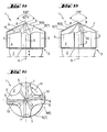
- a rotary shaft 2 revolving about an axis of rotation A and along this striking drill 1 has a helical shaft 2 at whose axial shaft end 3 a one-piece hard-material head 4 is butt-brazed, which has four arms extending radially in a cruciform manner, Leg 5, each with two diametrically opposite main cutting edges 6 and minor cutting edges 7, wherein the main cutting edges 6 and the minor cutting edges 7 extend axially from a drill tip 8 axially to the radially outer edge and the envelope surface 9 of the minor cutting edges 7 completely within the envelope surface 9 of the main cutting edge. 6 lies and this touches only on the drill bit 8.
- the main cutting edges 6 are straight in axial projection starting from the drill tip 8 and the secondary cutting edges 7 are uniformly convexly curved in the direction of rotation [omega] to the nearest main cutting edge 6.
- the leg 5 of the main cutting edge 6 forms on the radially outer edge on the direction of rotation side a tangentially inclined ramp surface 10, which is axially spaced from the main cutting edge 6.
Landscapes
- Engineering & Computer Science (AREA)
- Mechanical Engineering (AREA)
- Mining & Mineral Resources (AREA)
- Drilling Tools (AREA)
- Processing Of Stones Or Stones Resemblance Materials (AREA)
- Earth Drilling (AREA)
- Perforating, Stamping-Out Or Severing By Means Other Than Cutting (AREA)
Abstract
Description
- Die Erfindung bezeichnet ein Bohrwerkzeug mit einem Hartstoffkopf, insbesondere einen Schlagbohrmeissel für Gestein und armierten Beton zur Verwendung mit einer leistungsstarken Handwerkzeugmaschine.
- Üblicherweise weisen derartige Bohrwerkzeuge einen sich axial zu einer Drehachse erstreckenden wendelförmigen Schaft auf, an dessen maschinenseitigem Schaftende ein Einsteckende zur Aufnahme in der Handwerkzeugmaschine und am gegenüberliegenden, werkstückseitigen Schaftende ein hart verlöteter Hartstoffkopf angeordnet ist.
- Nach der
W02005061838 ist ein Schlagbohrmeissel für Gestein mit einem einstückigen, Hartstoffkopf mit vier kreuzförmig angeordneten, in Drehrichtung konvex gekrümmten, Schneiden und einer Zentrierspitze bekannt. - Nach der
EP1604762 weist ein Schlagbohrmeissel für Gestein mit einem stumpf aufgelöteten, einstückigen Hartstoffeinsatz vier kreuzförmig radial angeordnete Schenkel auf, welche zwei diametral gegenüberliegende gerade Hauptschneiden und zwei diametral gegenüberliegende, zur Drehrichtung konkav gekrümmte Nebenschneiden ausbilden. Die Nebenschneiden mit einer in Drehrichtung tangential geneigten Auflauffläche (zum maschinenseitig axialen Abheben des Schlagbohrmeissels bei einem Armierungseisentreffer) erstrecken sich ausschliesslich im radial äusseren Bereich. Ausschliesslich im radial inneren Zentrierbereich sind je zwei diametral gegenüberliegende Zentrierschneiden vorhanden, die axial linear zu einer von den Hauptschneiden ausgebildeten Bohrspitze verlaufen. Die radial innere Hüllfläche des Zentrierbereiches hat dabei einen spitzeren Dachkantenwinkel als die radial äussere Hüllfläche der Schenkel. - Die Aufgabe der Erfindung besteht in einer weiteren Verbesserung der Bohrleistung sowie der Robustheit gegenüber Armierungseisentreffern.
- Die Aufgabe wird im Wesentlichen durch die Merkmale des Anspruchs 1 gelöst. Vorteilhafte Weiterbildungen ergeben sich aus den Unteransprüchen.
- So weist ein um eine Drehachse zumindest teilweise drehend antreibbares Bohrwerkzeug einen wendelförmigen Schaft auf, an dessen axialem Schaftende ein einstückiger Hartstoffkopf stoffschlüssig befestigt ist, welcher vier, sich kreuzförmig radial erstreckende, Schenkel mit je zwei diametral gegenüberliegenden Hauptschneiden und Nebenschneiden aufweist, wobei die Hauptschneiden und die Nebenschneiden von einer Bohrerspitze ausgehend axial (d.h. nur bezüglich der axialen Komponente) streng monoton bis zum radial äusseren Rand verlaufen und die Hüllfläche der Nebenschneiden vollständig innerhalb der Hüllfläche der Hauptschneiden liegt und diese nur an der Bohrerspitze berührt.
- Durch die vollständig innerhalb der Hüllfläche der Hauptschneiden liegende Hüllfläche der Nebenschneiden ist ein radial gemittelter Dachkantenwinkel der Nebenschneiden kleiner als der der Hauptschneiden, wodurch mit dem für die Bohrleistung wesentlichen äusseren Radialbereich die axiale Anpresskraft auf die Hauptschneiden konzentriert wird, wobei die Nebenschneiden zu deren Schutz bei Armierungseisentreffern dienen, und im inneren Zentralbereich durch alle vier Schneiden ein gutes Anbohr- und Führungsverhalten erzielt wird.
- Vorteilhaft liegt eine Winkeldifferenz der radial gemittelten Dachkantenwinkel im Bereich zwischen 2° und 10°, wodurch optimale Bohrleistung und Robustheit erzielt wird.
- Vorteilhaft verlaufen die Hauptschneiden und die Nebenschneiden axial linear, wodurch deren Hüllflächen exakt kegelig ausgebildet sind.
- Vorteilhaft sind die Hauptschneiden in axialer Projektion von der Bohrerspitze ausgehend gerade ausgebildet, wodurch sie eine minimale Länge und somit bei gegebener Anpresskraft eine maximale Linienkraftdichte aufweisen.
- Vorteilhaft sind die Nebenschneiden in axialer Projektion von der Bohrerspitze ausgehend zur nächstliegenden Hauptschneide (in Drehrichtung) konvex gekrümmt ausgebildet, wodurch das hauptsächlich von der (anderen, in Drehrichtung nachfolgenden) Hauptschneide abrasiv abgetragene Bohrklein besser in den wendelförmigen Schaft gefördert wird.
- Vorteilhaft sind die Nebenschneiden in axialer Projektion von der Bohrerspitze ausgehend gleichförmig gekrümmt (d.h. mit einem konstanten Krümmungsradius), wodurch lokale Stellen starker Krümmung vermieden werden, an denen sich Bohrklein ablagern kann.
- Vorteilhaft bildet der Schenkel der Hauptschneide am radial äusseren Rand drehrichtungsseitig eine tangential geneigte Auflauffläche aus, welche von der Hauptschneide axial beabstandet ist, wodurch an der Hauptschneide ebenfalls eine Auflauffläche ausgebildet wird, die insbesondere bei seitlichen Armierungseisentreffern ein Festfressen der Hauptschneidenecke im duktilen Armierungseisen verhindert.
- Die Erfindung wird bezüglich eines vorteilhaften Ausführungsbeispiels näher erläutert mit:
- Fig. 1a, 1 b, 1 c als Bohrwerkzeug in Vorderansicht, Seitenansicht und Aufsicht
- Nach den Fig. 1a, 1b und 1c weist ein um eine Drehachse A drehend und längs dieser schlagendes Bohrwerkzeug 1 einen wendelförmigen Schaft 2 auf, an dessen axialem Schaftende 3 ein einstückiger Hartstoffkopf 4 stumpf hart aufgelötet ist, welcher vier, sich kreuzförmig radial erstreckende, Schenkel 5 mit je zwei diametral gegenüberliegenden Hauptschneiden 6 und Nebenschneiden 7 aufweist, wobei die Hauptschneiden 6 und die Nebenschneiden 7 von einer Bohrerspitze 8 ausgehend axial linear bis zum radial äusseren Rand verlaufen und die Hüllfläche 9 der Nebenschneiden 7 vollständig innerhalb der Hüllfläche 9 der Hauptschneiden 6 liegt und diese nur an der Bohrerspitze 8 berührt. Die Winkeldifferenz von in die Kegelspitze eingeschriebenen Dachkantenwinkeln zwischen den Hüllflächen 9 beträgt 130° - 125° = 5°. Die Hauptschneiden 6 sind in axialer Projektion von der Bohrerspitze 8 ausgehend gerade ausgebildet und die Nebenschneiden 7 in Drehrichtung [omega] zur nächstliegenden Hauptschneide 6 gleichförmig konvex gekrümmt. Der Schenkel 5 der Hauptschneide 6 bildet am radial äusseren Rand drehrichtungsseitig eine tangential geneigte Auflauffläche 10 aus, welche von der Hauptschneide 6 axial beabstandet ist.
Claims (7)
- Ein um eine Drehachse (A) zumindest teilweise drehend antreibbares Bohrwerkzeug mit einem wendelförmigen Schaft (2), an dessen axialem Schaftende (3) ein einstückiger Hartstoffkopf (4) stoffschlüssig befestigt ist, welcher vier, sich kreuzförmig radial erstreckende, Schenkel (5) mit je zwei diametral gegenüberliegenden Hauptschneiden (6) und Nebenschneiden (7) aufweist, dadurch gekennzeichnet, dass die Hauptschneiden (6) und die Nebenschneiden (7) von einer Bohrerspitze (8) ausgehend axial streng monoton bis zum radial äusseren Rand verlaufen und eine Hüllfläche (9) der Nebenschneiden (7) vollständig innerhalb der Hüllfläche (9) der Hauptschneiden (6) liegt und diese nur an der Bohrerspitze (8) berührt.
- Bohrwerkzeug nach Anspruch 1, dadurch gekennzeichnet, dass eine Winkeldifferenz von radial gemittelten Dachkantenwinkeln der Hüllflächen (9) im Bereich zwischen 2° und 10° liegt.
- Bohrwerkzeug nach Anspruch 1 oder 2, dadurch gekennzeichnet, dass die Hauptschneiden (6) und die Nebenschneiden (7) axial linear verlaufen.
- Bohrwerkzeug nach einem der Ansprüche 1 bis 3, dadurch gekennzeichnet, dass die Hauptschneiden (6) in axialer Projektion von der Bohrerspitze (8) ausgehend gerade ausgebildet sind.
- Bohrwerkzeug nach einem der Ansprüche 1 bis 4, dadurch gekennzeichnet, dass die Nebenschneiden (7) in axialer Projektion von der Bohrerspitze (8) ausgehend zur tangential nächstliegenden Hauptschneide (6) konvex gekrümmt ausgebildet sind.
- Bohrwerkzeug nach Anspruch 5, dadurch gekennzeichnet, dass die Nebenschneiden (7) gleichförmig gekrümmt sind.
- Bohrwerkzeug nach einem der Ansprüche 1 bis 6, dadurch gekennzeichnet, dass der Schenkel (5) der Hauptschneide (6) am radial äusseren Rand drehrichtungsseitig eine tangential geneigte Auflauffläche (10) ausbildet, welche von der Hauptschneide (6) axial beabstandet ist.
Applications Claiming Priority (1)
| Application Number | Priority Date | Filing Date | Title |
|---|---|---|---|
| DE102006035443A DE102006035443B3 (de) | 2006-11-15 | 2006-11-15 | Bohrwerkzeug mit Hartstoffkopf |
Publications (3)
| Publication Number | Publication Date |
|---|---|
| EP1923160A2 true EP1923160A2 (de) | 2008-05-21 |
| EP1923160A3 EP1923160A3 (de) | 2008-07-30 |
| EP1923160B1 EP1923160B1 (de) | 2010-03-31 |
Family
ID=38955132
Family Applications (1)
| Application Number | Title | Priority Date | Filing Date |
|---|---|---|---|
| EP07021806A Active EP1923160B1 (de) | 2006-11-15 | 2007-11-09 | Bohrwerkzeug mit Hartstoffkopf |
Country Status (6)
| Country | Link |
|---|---|
| US (1) | US20080110679A1 (de) |
| EP (1) | EP1923160B1 (de) |
| CN (1) | CN101181806A (de) |
| AT (1) | ATE462521T1 (de) |
| AU (1) | AU2007234490B2 (de) |
| DE (2) | DE102006035443B3 (de) |
Cited By (1)
| Publication number | Priority date | Publication date | Assignee | Title |
|---|---|---|---|---|
| WO2010057706A1 (de) * | 2008-11-24 | 2010-05-27 | Robert Bosch Gmbh | Bohrwerkzeug für bohr- und/oder meisselgeräte |
Families Citing this family (9)
| Publication number | Priority date | Publication date | Assignee | Title |
|---|---|---|---|---|
| US7861807B2 (en) | 2008-12-03 | 2011-01-04 | Black & Decker Inc. | Drill bit including one piece cutting head |
| JP5276486B2 (ja) * | 2009-03-13 | 2013-08-28 | 富士重工業株式会社 | ドリル |
| CN101947665A (zh) * | 2010-09-10 | 2011-01-19 | 安徽华星消防设备(集团)有限公司 | 模具打孔冲击钻钻头 |
| EP2669033B1 (de) | 2012-05-29 | 2015-11-04 | Black & Decker Inc. | Schneidkopf für einen Bohrer. |
| DE102016211953A1 (de) * | 2016-06-30 | 2018-01-04 | Robert Bosch Gmbh | Bohrwerkzeug |
| EP4059643A1 (de) * | 2021-03-18 | 2022-09-21 | Black & Decker Inc. | Einteiliger schneidkopf für einen bohrer |
| EP4108370A1 (de) * | 2021-06-22 | 2022-12-28 | Hilti Aktiengesellschaft | Flügeverfahren und hammerbohrwerkzeug |
| CN114147260A (zh) * | 2021-12-09 | 2022-03-08 | 浙江立昌科技有限公司 | 一种合金钻头 |
| US20240390991A1 (en) | 2023-05-23 | 2024-11-28 | Iscar, Ltd. | Cutting Head Having Two Pairs of Cutting Arms with Unequal Cutting Diameters, and Rotary Cutting Tool |
Family Cites Families (8)
| Publication number | Priority date | Publication date | Assignee | Title |
|---|---|---|---|---|
| US2673716A (en) * | 1950-09-02 | 1954-03-30 | Clyde E Avery | Bit |
| DE3621414A1 (de) * | 1986-06-26 | 1988-01-07 | Hawera Probst Kg Hartmetall | Bohrwerkzeug |
| DE19724373A1 (de) * | 1997-06-10 | 1998-12-17 | Hilti Ag | Gesteinsbohrer |
| DE10006932A1 (de) * | 2000-02-16 | 2001-08-23 | Hilti Ag | Bohrwerkzeug für Gestein |
| DE10006936A1 (de) * | 2000-02-16 | 2001-08-23 | Hilti Ag | Bohrwerkzeug für Gestein |
| DE10009732A1 (de) * | 2000-03-02 | 2001-09-06 | Hawera Probst Gmbh | Gesteinsbohrer |
| DE10361501A1 (de) * | 2003-12-23 | 2005-07-28 | Hawera Probst Gmbh | Bohrwerkzeug |
| DE102004028098A1 (de) * | 2004-06-09 | 2005-12-29 | Hilti Ag | Bohrer |
-
2006
- 2006-11-15 DE DE102006035443A patent/DE102006035443B3/de not_active Expired - Fee Related
-
2007
- 2007-11-09 AT AT07021806T patent/ATE462521T1/de active
- 2007-11-09 DE DE502007003289T patent/DE502007003289D1/de active Active
- 2007-11-09 EP EP07021806A patent/EP1923160B1/de active Active
- 2007-11-09 US US11/983,470 patent/US20080110679A1/en not_active Abandoned
- 2007-11-13 AU AU2007234490A patent/AU2007234490B2/en not_active Ceased
- 2007-11-13 CN CNA2007101700947A patent/CN101181806A/zh active Pending
Cited By (3)
| Publication number | Priority date | Publication date | Assignee | Title |
|---|---|---|---|---|
| WO2010057706A1 (de) * | 2008-11-24 | 2010-05-27 | Robert Bosch Gmbh | Bohrwerkzeug für bohr- und/oder meisselgeräte |
| EP2481505A1 (de) * | 2008-11-24 | 2012-08-01 | Robert Bosch Gmbh | Bohrwerkzeug, insbesondere für Bohr- und/oder Meißelgeräte |
| RU2525950C2 (ru) * | 2008-11-24 | 2014-08-20 | Роберт Бош Гмбх | Сверлильный инструмент для технологических машин вращательного и/или ударного действия |
Also Published As
| Publication number | Publication date |
|---|---|
| DE102006035443B3 (de) | 2008-02-21 |
| ATE462521T1 (de) | 2010-04-15 |
| AU2007234490B2 (en) | 2010-05-27 |
| AU2007234490A1 (en) | 2008-05-29 |
| EP1923160B1 (de) | 2010-03-31 |
| US20080110679A1 (en) | 2008-05-15 |
| CN101181806A (zh) | 2008-05-21 |
| EP1923160A3 (de) | 2008-07-30 |
| DE502007003289D1 (de) | 2010-05-12 |
Similar Documents
| Publication | Publication Date | Title |
|---|---|---|
| EP1923160B1 (de) | Bohrwerkzeug mit Hartstoffkopf | |
| EP1125664B1 (de) | Bohrwerkzeug für Gestein | |
| EP1125663B1 (de) | Bohrwerkzeug für Gestein | |
| EP1604762B1 (de) | Bohrer | |
| DE19545648A1 (de) | Drehschlag-Wendelbohrer | |
| EP1259699A2 (de) | Gesteinsbohrer | |
| EP1225300A2 (de) | Gesteinsbohrer | |
| EP1455978B1 (de) | Schlag- oder hammerbohrer | |
| EP2050530A1 (de) | Schlagbohrwerkzeug | |
| EP1382409B1 (de) | Betonbohrer | |
| EP1923159A1 (de) | Bohrwerkzeug mit Hartstoffkopf | |
| EP3656494A1 (de) | Stufenbohrer | |
| EP2367654B1 (de) | Bohrwerkzeug für Bohr- und/oder Meisselgeräte | |
| DE102006000221A1 (de) | Hartstoffbohrkopf | |
| EP1892070A2 (de) | Bohrwerkzeug mit Hartstoffeinsatz | |
| EP0778390B1 (de) | Drehschlag-Wendelbohrer | |
| DE102009056484A1 (de) | Wendelbohrer mit zwei Hauptschneiden und einer Querschneide | |
| EP1188897B1 (de) | Gesteinsbohrer | |
| DE102011090063B4 (de) | Hammerbohrkrone | |
| EP1923158B1 (de) | Bohrwerkzeug mit Hartstoffeinsatz | |
| DE2821248C3 (de) | Gesteinsbohrkrone zum Drehschlagbohrer | |
| WO2010057707A1 (de) | Bohrwerkzeug insbesondere für bohr- und/oder meisselgeräte | |
| DE102012015369A1 (de) | Bohrkopf für einen Bohrer und Bohrer | |
| DE102023206483A1 (de) | Bohrwerkzeug mit einem Bohrkopf | |
| DE102023206478A1 (de) | Bohrwerkzeug mit einem Bohrkopf, der eine zentrale Pyramide aufweist |
Legal Events
| Date | Code | Title | Description |
|---|---|---|---|
| PUAI | Public reference made under article 153(3) epc to a published international application that has entered the european phase |
Free format text: ORIGINAL CODE: 0009012 |
|
| AK | Designated contracting states |
Kind code of ref document: A2 Designated state(s): AT BE BG CH CY CZ DE DK EE ES FI FR GB GR HU IE IS IT LI LT LU LV MC MT NL PL PT RO SE SI SK TR |
|
| AX | Request for extension of the european patent |
Extension state: AL BA HR MK RS |
|
| PUAL | Search report despatched |
Free format text: ORIGINAL CODE: 0009013 |
|
| AK | Designated contracting states |
Kind code of ref document: A3 Designated state(s): AT BE BG CH CY CZ DE DK EE ES FI FR GB GR HU IE IS IT LI LT LU LV MC MT NL PL PT RO SE SI SK TR |
|
| AX | Request for extension of the european patent |
Extension state: AL BA HR MK RS |
|
| 17P | Request for examination filed |
Effective date: 20090130 |
|
| AKX | Designation fees paid |
Designated state(s): AT BE BG CH CY CZ DE DK EE ES FI FR GB GR HU IE IS IT LI LT LU LV MC MT NL PL PT RO SE SI SK TR |
|
| GRAP | Despatch of communication of intention to grant a patent |
Free format text: ORIGINAL CODE: EPIDOSNIGR1 |
|
| GRAS | Grant fee paid |
Free format text: ORIGINAL CODE: EPIDOSNIGR3 |
|
| GRAA | (expected) grant |
Free format text: ORIGINAL CODE: 0009210 |
|
| AK | Designated contracting states |
Kind code of ref document: B1 Designated state(s): AT BE BG CH CY CZ DE DK EE ES FI FR GB GR HU IE IS IT LI LT LU LV MC MT NL PL PT RO SE SI SK TR |
|
| REG | Reference to a national code |
Ref country code: CH Ref legal event code: EP Ref country code: GB Ref legal event code: FG4D Free format text: NOT ENGLISH |
|
| REG | Reference to a national code |
Ref country code: IE Ref legal event code: FG4D |
|
| REF | Corresponds to: |
Ref document number: 502007003289 Country of ref document: DE Date of ref document: 20100512 Kind code of ref document: P |
|
| REG | Reference to a national code |
Ref country code: NL Ref legal event code: VDEP Effective date: 20100331 |
|
| PG25 | Lapsed in a contracting state [announced via postgrant information from national office to epo] |
Ref country code: LT Free format text: LAPSE BECAUSE OF FAILURE TO SUBMIT A TRANSLATION OF THE DESCRIPTION OR TO PAY THE FEE WITHIN THE PRESCRIBED TIME-LIMIT Effective date: 20100331 |
|
| LTIE | Lt: invalidation of european patent or patent extension |
Effective date: 20100331 |
|
| PG25 | Lapsed in a contracting state [announced via postgrant information from national office to epo] |
Ref country code: SI Free format text: LAPSE BECAUSE OF FAILURE TO SUBMIT A TRANSLATION OF THE DESCRIPTION OR TO PAY THE FEE WITHIN THE PRESCRIBED TIME-LIMIT Effective date: 20100331 Ref country code: FI Free format text: LAPSE BECAUSE OF FAILURE TO SUBMIT A TRANSLATION OF THE DESCRIPTION OR TO PAY THE FEE WITHIN THE PRESCRIBED TIME-LIMIT Effective date: 20100331 Ref country code: PL Free format text: LAPSE BECAUSE OF FAILURE TO SUBMIT A TRANSLATION OF THE DESCRIPTION OR TO PAY THE FEE WITHIN THE PRESCRIBED TIME-LIMIT Effective date: 20100331 Ref country code: LV Free format text: LAPSE BECAUSE OF FAILURE TO SUBMIT A TRANSLATION OF THE DESCRIPTION OR TO PAY THE FEE WITHIN THE PRESCRIBED TIME-LIMIT Effective date: 20100331 |
|
| REG | Reference to a national code |
Ref country code: IE Ref legal event code: FD4D |
|
| PG25 | Lapsed in a contracting state [announced via postgrant information from national office to epo] |
Ref country code: EE Free format text: LAPSE BECAUSE OF FAILURE TO SUBMIT A TRANSLATION OF THE DESCRIPTION OR TO PAY THE FEE WITHIN THE PRESCRIBED TIME-LIMIT Effective date: 20100331 Ref country code: SE Free format text: LAPSE BECAUSE OF FAILURE TO SUBMIT A TRANSLATION OF THE DESCRIPTION OR TO PAY THE FEE WITHIN THE PRESCRIBED TIME-LIMIT Effective date: 20100331 Ref country code: RO Free format text: LAPSE BECAUSE OF FAILURE TO SUBMIT A TRANSLATION OF THE DESCRIPTION OR TO PAY THE FEE WITHIN THE PRESCRIBED TIME-LIMIT Effective date: 20100331 Ref country code: NL Free format text: LAPSE BECAUSE OF FAILURE TO SUBMIT A TRANSLATION OF THE DESCRIPTION OR TO PAY THE FEE WITHIN THE PRESCRIBED TIME-LIMIT Effective date: 20100331 Ref country code: ES Free format text: LAPSE BECAUSE OF FAILURE TO SUBMIT A TRANSLATION OF THE DESCRIPTION OR TO PAY THE FEE WITHIN THE PRESCRIBED TIME-LIMIT Effective date: 20100712 Ref country code: CY Free format text: LAPSE BECAUSE OF FAILURE TO SUBMIT A TRANSLATION OF THE DESCRIPTION OR TO PAY THE FEE WITHIN THE PRESCRIBED TIME-LIMIT Effective date: 20100331 |
|
| PG25 | Lapsed in a contracting state [announced via postgrant information from national office to epo] |
Ref country code: IS Free format text: LAPSE BECAUSE OF FAILURE TO SUBMIT A TRANSLATION OF THE DESCRIPTION OR TO PAY THE FEE WITHIN THE PRESCRIBED TIME-LIMIT Effective date: 20100731 Ref country code: SK Free format text: LAPSE BECAUSE OF FAILURE TO SUBMIT A TRANSLATION OF THE DESCRIPTION OR TO PAY THE FEE WITHIN THE PRESCRIBED TIME-LIMIT Effective date: 20100331 Ref country code: CZ Free format text: LAPSE BECAUSE OF FAILURE TO SUBMIT A TRANSLATION OF THE DESCRIPTION OR TO PAY THE FEE WITHIN THE PRESCRIBED TIME-LIMIT Effective date: 20100331 |
|
| PG25 | Lapsed in a contracting state [announced via postgrant information from national office to epo] |
Ref country code: PT Free format text: LAPSE BECAUSE OF FAILURE TO SUBMIT A TRANSLATION OF THE DESCRIPTION OR TO PAY THE FEE WITHIN THE PRESCRIBED TIME-LIMIT Effective date: 20100802 Ref country code: DK Free format text: LAPSE BECAUSE OF FAILURE TO SUBMIT A TRANSLATION OF THE DESCRIPTION OR TO PAY THE FEE WITHIN THE PRESCRIBED TIME-LIMIT Effective date: 20100331 Ref country code: IE Free format text: LAPSE BECAUSE OF FAILURE TO SUBMIT A TRANSLATION OF THE DESCRIPTION OR TO PAY THE FEE WITHIN THE PRESCRIBED TIME-LIMIT Effective date: 20100331 |
|
| PLBE | No opposition filed within time limit |
Free format text: ORIGINAL CODE: 0009261 |
|
| STAA | Information on the status of an ep patent application or granted ep patent |
Free format text: STATUS: NO OPPOSITION FILED WITHIN TIME LIMIT |
|
| 26N | No opposition filed |
Effective date: 20110104 |
|
| PG25 | Lapsed in a contracting state [announced via postgrant information from national office to epo] |
Ref country code: IT Free format text: LAPSE BECAUSE OF FAILURE TO SUBMIT A TRANSLATION OF THE DESCRIPTION OR TO PAY THE FEE WITHIN THE PRESCRIBED TIME-LIMIT Effective date: 20100331 |
|
| BERE | Be: lapsed |
Owner name: HILTI AKTIENGESELLSCHAFT Effective date: 20101130 |
|
| PG25 | Lapsed in a contracting state [announced via postgrant information from national office to epo] |
Ref country code: MC Free format text: LAPSE BECAUSE OF NON-PAYMENT OF DUE FEES Effective date: 20101130 |
|
| PG25 | Lapsed in a contracting state [announced via postgrant information from national office to epo] |
Ref country code: BE Free format text: LAPSE BECAUSE OF NON-PAYMENT OF DUE FEES Effective date: 20101130 |
|
| PG25 | Lapsed in a contracting state [announced via postgrant information from national office to epo] |
Ref country code: MT Free format text: LAPSE BECAUSE OF FAILURE TO SUBMIT A TRANSLATION OF THE DESCRIPTION OR TO PAY THE FEE WITHIN THE PRESCRIBED TIME-LIMIT Effective date: 20100331 |
|
| REG | Reference to a national code |
Ref country code: CH Ref legal event code: PL |
|
| PG25 | Lapsed in a contracting state [announced via postgrant information from national office to epo] |
Ref country code: LI Free format text: LAPSE BECAUSE OF NON-PAYMENT OF DUE FEES Effective date: 20111130 Ref country code: CH Free format text: LAPSE BECAUSE OF NON-PAYMENT OF DUE FEES Effective date: 20111130 |
|
| PG25 | Lapsed in a contracting state [announced via postgrant information from national office to epo] |
Ref country code: BG Free format text: LAPSE BECAUSE OF FAILURE TO SUBMIT A TRANSLATION OF THE DESCRIPTION OR TO PAY THE FEE WITHIN THE PRESCRIBED TIME-LIMIT Effective date: 20100331 Ref country code: LU Free format text: LAPSE BECAUSE OF NON-PAYMENT OF DUE FEES Effective date: 20101109 Ref country code: HU Free format text: LAPSE BECAUSE OF FAILURE TO SUBMIT A TRANSLATION OF THE DESCRIPTION OR TO PAY THE FEE WITHIN THE PRESCRIBED TIME-LIMIT Effective date: 20101001 |
|
| PG25 | Lapsed in a contracting state [announced via postgrant information from national office to epo] |
Ref country code: TR Free format text: LAPSE BECAUSE OF FAILURE TO SUBMIT A TRANSLATION OF THE DESCRIPTION OR TO PAY THE FEE WITHIN THE PRESCRIBED TIME-LIMIT Effective date: 20100331 |
|
| PG25 | Lapsed in a contracting state [announced via postgrant information from national office to epo] |
Ref country code: BG Free format text: LAPSE BECAUSE OF FAILURE TO SUBMIT A TRANSLATION OF THE DESCRIPTION OR TO PAY THE FEE WITHIN THE PRESCRIBED TIME-LIMIT Effective date: 20100630 |
|
| REG | Reference to a national code |
Ref country code: AT Ref legal event code: MM01 Ref document number: 462521 Country of ref document: AT Kind code of ref document: T Effective date: 20121130 |
|
| PG25 | Lapsed in a contracting state [announced via postgrant information from national office to epo] |
Ref country code: AT Free format text: LAPSE BECAUSE OF NON-PAYMENT OF DUE FEES Effective date: 20121130 |
|
| PG25 | Lapsed in a contracting state [announced via postgrant information from national office to epo] |
Ref country code: GR Free format text: LAPSE BECAUSE OF FAILURE TO SUBMIT A TRANSLATION OF THE DESCRIPTION OR TO PAY THE FEE WITHIN THE PRESCRIBED TIME-LIMIT Effective date: 20100331 |
|
| REG | Reference to a national code |
Ref country code: FR Ref legal event code: PLFP Year of fee payment: 9 |
|
| REG | Reference to a national code |
Ref country code: FR Ref legal event code: PLFP Year of fee payment: 10 |
|
| REG | Reference to a national code |
Ref country code: FR Ref legal event code: PLFP Year of fee payment: 11 |
|
| PGFP | Annual fee paid to national office [announced via postgrant information from national office to epo] |
Ref country code: DE Payment date: 20251119 Year of fee payment: 19 |
|
| PGFP | Annual fee paid to national office [announced via postgrant information from national office to epo] |
Ref country code: GB Payment date: 20251121 Year of fee payment: 19 |
|
| PGFP | Annual fee paid to national office [announced via postgrant information from national office to epo] |
Ref country code: FR Payment date: 20251121 Year of fee payment: 19 |