EP1923136A1 - Container with lid - Google Patents
Container with lid Download PDFInfo
- Publication number
- EP1923136A1 EP1923136A1 EP07022241A EP07022241A EP1923136A1 EP 1923136 A1 EP1923136 A1 EP 1923136A1 EP 07022241 A EP07022241 A EP 07022241A EP 07022241 A EP07022241 A EP 07022241A EP 1923136 A1 EP1923136 A1 EP 1923136A1
- Authority
- EP
- European Patent Office
- Prior art keywords
- lid
- opening
- lid portion
- container
- container body
- Prior art date
- Legal status (The legal status is an assumption and is not a legal conclusion. Google has not performed a legal analysis and makes no representation as to the accuracy of the status listed.)
- Withdrawn
Links
Images


Classifications
-
- B—PERFORMING OPERATIONS; TRANSPORTING
- B01—PHYSICAL OR CHEMICAL PROCESSES OR APPARATUS IN GENERAL
- B01L—CHEMICAL OR PHYSICAL LABORATORY APPARATUS FOR GENERAL USE
- B01L3/00—Containers or dishes for laboratory use, e.g. laboratory glassware; Droppers
- B01L3/50—Containers for the purpose of retaining a material to be analysed, e.g. test tubes
- B01L3/508—Rigid containers without fluid transport within
- B01L3/5082—Test tubes per se
- B01L3/50825—Closing or opening means, corks, bungs
-
- B—PERFORMING OPERATIONS; TRANSPORTING
- B01—PHYSICAL OR CHEMICAL PROCESSES OR APPARATUS IN GENERAL
- B01L—CHEMICAL OR PHYSICAL LABORATORY APPARATUS FOR GENERAL USE
- B01L2200/00—Solutions for specific problems relating to chemical or physical laboratory apparatus
- B01L2200/02—Adapting objects or devices to another
- B01L2200/026—Fluid interfacing between devices or objects, e.g. connectors, inlet details
-
- B—PERFORMING OPERATIONS; TRANSPORTING
- B01—PHYSICAL OR CHEMICAL PROCESSES OR APPARATUS IN GENERAL
- B01L—CHEMICAL OR PHYSICAL LABORATORY APPARATUS FOR GENERAL USE
- B01L2300/00—Additional constructional details
- B01L2300/04—Closures and closing means
- B01L2300/041—Connecting closures to device or container
- B01L2300/043—Hinged closures
-
- B—PERFORMING OPERATIONS; TRANSPORTING
- B01—PHYSICAL OR CHEMICAL PROCESSES OR APPARATUS IN GENERAL
- B01L—CHEMICAL OR PHYSICAL LABORATORY APPARATUS FOR GENERAL USE
- B01L2300/00—Additional constructional details
- B01L2300/04—Closures and closing means
- B01L2300/041—Connecting closures to device or container
- B01L2300/044—Connecting closures to device or container pierceable, e.g. films, membranes
Definitions
- the present invention generally relates to a container with lid. More specifically, the invention relates to a container (or a vessel) having a lid for holding the interior thereof in a sealed state.
- microcentrifuge tubes having a volume of 1.5 ml have been used as specimen sampling containers, sample assaying containers and so forth in various fields of biochemistry, such as genetic engineering, cell culture and pharmacological evaluation.
- microcentrifuge tube is used as a sample assaying container, a sample is often solved in a volatile solvent, such as methanol, when the sample is assayed.
- a volatile solvent such as methanol
- the liquid sample evaporates during operation, so that the concentration of the sample varies or the amount of the sample is insufficient by evaporation.
- a container with lid comprises: a tubular container body having a bottom at one end thereof and having an opening at the other end thereof; a first lid portion capable of opening and closing the opening of the container body; a second lid portion capable of opening and closing an opening which is formed in the first lid portion; a first connecting portion which connects the first lid portion with the container body; and a second connecting portion which connects the second lid portion with the first lid portion, wherein the container body, the first and second lid portions, and the first and second connecting portions are integral-molded.
- a first sealing member is preferably mounted on the first lid portion for sealing a gap between a peripheral portion of the first lid portion and the opening of the container body when the opening of the container body is closed by the first lid portion.
- the first sealing member preferably has a closing portion capable of opening and closing a central portion of the opening of the first lid portion, and the closing portion preferably has a cut.
- a second sealing member is preferably mounted on the second lid portion for sealing a gap between the second lid portion and the opening of the first lid portion when the opening of the first lid portion is closed by the second lid portion.
- the first connecting portion is preferably folded when the opening of the container body is closed by the first lid portion
- the second connecting portion is preferably folded when the opening of the first lid portion is closed by the second lid portion.
- the first and second lid portions, and the first and second connecting portions are preferably made of a resin material
- the first and second sealing members are preferably made of a material which is softer than the resin material.
- the present invention it is possible to prevent evaporation of a liquid, which is stored in the container, even if the liquid is continuously pipetted from the container.
- a container 10 with lid in this preferred embodiment comprises: a tubular container body 12 having a bottom at the lower end thereof and an opening 12a at the upper end thereof; a first lid portion 14 for opening and closing the opening 12a of the container body 12; a second lid portion 16 for opening and closing an opening 14a which is formed in the first lid portion 14; a first connecting portion 18 which connects the container body 12 with the first lid portion 14; and a second connecting portion 20 which connects the first lid portion 14 with the second lid portion 16.
- the container body 12, first lid portion 14, second lid portion 16, first connecting portion 18 and second connecting portion 20 are made of a flexible resin material, such as polypropylene, having excellent chemical resistance and heat resistance, and are integral-molded by injection molding or the like.
- the container 10 with lid in this preferred embodiment further comprises a first sealing member 22 mounted on the first lid portion 14, and a second sealing member 24 mounted on the second lid portion 16.
- the container body 12 comprises: a substantially cylindrical large-diameter portion 12c having a substantially circular opening 12a at the upper end thereof; a substantially cylindrical small-diameter portion 12d, the diameter of which is smaller than that of the large-diameter portion 12c; and a tapered portion 12e having a substantially circular bottom portion 12b at the lower end thereof.
- the small-diameter portion 12d extends downwards from the bottom of the large-diameter portion 12c, and the tapered portion 12e extends downwards from the bottom of the small-diameter portion 12e, so that a liquid storing chamber 12f having a volume of about 0.5 to 1.5 ml is formed in the container body 12.
- the first lid portion 14 comprises a substantially cylindrical member which has a substantially cylindrical opening 14a.
- the first lid portion 14 has a groove portion 14b, which is formed in the top face thereof (the upper surface in FIG. 5) and which extends in circumferential directions so that a cylindrical portion 22b (see FIG. 9) of the first sealing member 22 (which will be described later) is fitted into the groove portion 14b, and a groove portion 14c which is formed in the side face thereof and which extends in circumferential directions so that an engaging portion 22c (see FIG. 9) of the first sealing member 22 (which will be described later) is fitted into the groove portion 14c.
- the outside diameter of a portion of the first lid portion 14 (a cylindrical portion shown by 14d in FIG.
- the second lid member 16 comprises: a substantially guitar-shaped flat plate portion 16a having a protruding portion 16b which extends from the side face of a substantially circular plate portion in substantially parallel thereto; and a cylindrical portion 16c which extends downwards from the bottom face of the substantially circular plate portion of the flat plate portion 16a in substantially perpendicular thereto and which has a substantially circular opening 16d at the lower end thereof.
- the side face of the cylindrical portion 16c has a groove portion 16e which extends in circumferential directions and into which a substantially cylindrical second sealing member 24 of a softer material, such as a rubber, e.g. silicon rubber, than the resin material is fitted.
- the outside diameter of the cylindrical portion 16c of the second lid portion 16 is slightly smaller than the inside diameter of the opening 14a of the first lid member 14.
- the first connecting portion 18 comprises a strip-like portion which substantially linearly extends from a portion near the upper end of the side face of the large-diameter portion 12c of the container body 12 to a portion near the lower end (the lower end in FIGS. 3 and 4) of the side face of the first lid portion 14 to connect the container body 12 with the first lid portion 14.
- the central portion of the first connecting portion 18, except for both end portions thereof, is thin to such an extent that it can be folded as shown in FIGS. 11 and 12.
- the opening 12a of the container body 12 can be closed by the first lid portion 14 as shown by arrow B in FIG. 4.
- the second connecting portion 20 comprises a strip-like portion substantially linearly extending from a portion near the lower end (the lower end in FIGS. 3 and 4) of the side face of the first lid portion 14, which is the opposite side face to the first connecting portion 18 in radial directions, to the side face of the flat plate portion 16a of the second lid portion 16, which is the opposite side face to the protruding portion 16b.
- the central portion of the second connecting portion 20, except for both end portions thereof, is thin to such an extent that it can be folded as shown in FIGS. 10 and 11.
- the opening 14a of the first lid portion 14 can be closed by the second lid portion 16 as shown by arrow A in FIG. 4.
- the first sealing member 22 is made of a softer material, such as a rubber, e.g. silicon rubber, than the resin material. As shown in FIGS. 7 through 9, the first sealing member 22 comprises a cylindrical portion 22b having a substantially circular opening 22a, an engaging portion 22c protruding and extending from the cylindrical portion 22b, and a closing portion for opening and closing the opening 22a of the cylindrical portion 22b.
- the engaging portion 22c protrudes outwards in radial directions from the upper end of the side face of the cylindrical portion 22b.
- the engaging portion 22c extends so as to have a substantially U-shaped cross section to form a gap 22e between the tip thereof and the cylindrical portion 22b, and extends over the entire periphery of the cylindrical portion 22b in circumferential directions thereof.
- the cylindrical portion 22b of the first sealing member 22 is fitted into the groove portion 14b which is formed in the top face of the first lid portion 14 (the upper surface in FIG. 5), and the tip portion of the engaging portion 22c is fitted into the groove portion 14c which is formed in the side face of the first lid portion 14.
- the first lid member 14 is clamped and held between the cylindrical portion 22b and the engaging portion 22c, so that the first sealing member 22 is fixed to the first lid member 14.
- the closing portion 22d comprises a substantially plate-like portion which is slightly inclined upwards as a distance from the center thereof decreases.
- the closing portion 22d has a cross-shaped cut 22f which is made therein so as to cross at the center thereof as shown in FIG. 7, so that a pipette chip or like can be inserted into the container body 12 through the cut 22f to pipette a liquid from the container body 12 even if the opening 12a of the container body 12 is closed by the first lid portion 14 as shown in FIG. 12.
- the first lid portion 14 of the container 10 with lid is open while the second lid portion 16 thereof is closed.
- a liquid such as a reagent
- the first lid portion 14 is closed.
- the opening 12a of the container body 12 is air-tightly closed by the first sealing member 22 which is mounted on the first lid portion 14
- the opening 14a of the first lid portion 14 is air-tightly closed by the second sealing member 24 which is mounted on the second lid portion 16, so that the interior of the container body 12 can be held in a sealed state.
- a liquid such as a reagent
- the interior of the container body 12 can be held in a sealed state by closing the first lid portion 14 without causing the operator's hand to contact the opening 14a of the first lid portion 14 and the closing portion 22d of the first sealing member 22, so that it is possible to prevent contamination of the liquid in the container body 12.
- the second lid portion 16 of the container 10 with lid is open while the first lid portion 14 thereof is closed.
- a pipette or the like can be inserted into the container body 12 through the cross-shaped cut 22f to pipette the liquid from the container body 12 while the interior of the container body 12 is substantially held in a sealed state without substantially opening the interior of the container body 12, since the cross-shaped cut 22f is made in the closing portion 22d of the first sealing member 22 although the peripheral portion of the opening 12a of the container body 12 is sealed by the first sealing member 22 which is mounted on the first lid portion 14.
- the opening and closing directions of the first lid portion 14 are opposite to those of the second lid portion 16, and the second lid portion 16 has the protruding portion 16b, so that it is possible to simply open and close the first lid portion 14 and second lid portion 16 by the operator's one hand.
- the large-diameter portion 12c of the container body 12, the first lid portion 14 and the second lid portion 14 in the container 10 with lid have been substantially linearly arranged in the above-described preferred embodiment, it is not always required to substantially linearly arrange them if they are integral-molded.
- first sealing member 22 has been mounted on the first lid portion 14 of the container 10 with lid in the above-described preferred embodiment, it is not required to provide the first sealing member 22 if the first lid portion 14 has a shape corresponding to the first sealing member 22 mounted thereon while a soft material is used as the material of the container body 12 and so forth to be integral-molded.
- the first sealing member 22 it is not required to provide the first sealing member 22 if a closing portion corresponding to the closing portion 22d of the first sealing member 22 is formed so as to be integrated with the first lid portion 14 and if the outside diameter of a portion (the cylindrical portion 14d) of the first lid portion 14 to be inserted into the opening 12a of the container body 12 is increased so that the cylindrical portion 14d of the first lid portion 14 can be fitted into the opening 12a of the container body 12 to seal the peripheral portion of the opening 12a of the container body 12 when the opening 12a of the container body 12 is closed by the first lid portion 14, while a soft material is used as the material of the container body 12 and so forth to be integral-molded. Also in such constructions, it is possible to prevent evaporation of a liquid, such as a reagent, in the container body 12 when the liquid is pipetted by means of a pipette chip.
- a liquid such as a reagent
- the second sealing member 24 has been mounted on the second lid portion 16 of the container 10 with lid in the above-described preferred embodiment, it is not required to provide the second sealing member 24 if the cylindrical portion 16c of the second lid portion 16 has a shape corresponding to the second sealing member 24 mounted thereon while a soft material is used as the material of the container body 12 and so forth to be integral-molded.
- the second sealing member 24 it is not required to provide the second sealing member 24 if the outside diameter of the cylindrical portion 16c of the second lid portion 16 is increased so that the cylindrical portion 16c of the second lid portion 16 can be fitted into the opening 14a of the first lid portion 14 to seal the opening 14a of the first lid portion 14 when the opening 14a of the first lid portion 14 is closed by the second lid portion 16, while a soft material is used as the material of the container body 12 and so forth to be integral-molded.
- a container with lid according to the present invention can be utilized as a microcentrifuge tube in various fields of biochemistry, such as genetic engineering, cell culture and pharmacological evaluation, and can be utilized as one of various containers, such as sampling containers, assaying containers, reaction containers and centrifuge containers.
Landscapes
- Health & Medical Sciences (AREA)
- Chemical & Material Sciences (AREA)
- Analytical Chemistry (AREA)
- General Health & Medical Sciences (AREA)
- Hematology (AREA)
- Clinical Laboratory Science (AREA)
- Chemical Kinetics & Catalysis (AREA)
- Automatic Analysis And Handling Materials Therefor (AREA)
- Devices For Use In Laboratory Experiments (AREA)
- Sampling And Sample Adjustment (AREA)
- Closures For Containers (AREA)
- Apparatus Associated With Microorganisms And Enzymes (AREA)
Abstract
Description
- The present invention generally relates to a container with lid. More specifically, the invention relates to a container (or a vessel) having a lid for holding the interior thereof in a sealed state.
- Conventionally, a large number of containers called microcentrifuge tubes having a volume of 1.5 ml have been used as specimen sampling containers, sample assaying containers and so forth in various fields of biochemistry, such as genetic engineering, cell culture and pharmacological evaluation.
- If such a microcentrifuge tube is used as a sample assaying container, a sample is often solved in a volatile solvent, such as methanol, when the sample is assayed. However, when a conventional microcentrifuge tube having no structure for holding the interior thereof in a sealed state is used for assaying a small amount of liquid sample, there are some cases where the liquid sample evaporates during operation, so that the concentration of the sample varies or the amount of the sample is insufficient by evaporation.
- As containers for preventing such evaporation of samples, there are proposed various sealed containers (sealed microcentrifuge tubes) with lid capable of holding the interior thereof in a sealed state (see, e.g.
Japanese Patent Publication No. 4-31945 Japanese Patent Laid-Open No. 10-323176 - However, if such a conventional container with lid proposed in
Japanese Patent Publication No. 4-31945 Japanese Patent Laid-Open No. 10-323176 - It is therefore an object of the present invention to eliminate the aforementioned problems and to provide a container with lid capable of preventing evaporation of a liquid, which is stored in the container, even if the liquid is continuously pipetted from the container.
- In order to accomplish the aforementioned obj ect, a container with lid according to the present invention comprises: a tubular container body having a bottom at one end thereof and having an opening at the other end thereof; a first lid portion capable of opening and closing the opening of the container body; a second lid portion capable of opening and closing an opening which is formed in the first lid portion; a first connecting portion which connects the first lid portion with the container body; and a second connecting portion which connects the second lid portion with the first lid portion, wherein the container body, the first and second lid portions, and the first and second connecting portions are integral-molded.
- In this container with lid, a first sealing member is preferably mounted on the first lid portion for sealing a gap between a peripheral portion of the first lid portion and the opening of the container body when the opening of the container body is closed by the first lid portion. In this case, the first sealing member preferably has a closing portion capable of opening and closing a central portion of the opening of the first lid portion, and the closing portion preferably has a cut.
- In the above-described container with lid, a second sealing member is preferably mounted on the second lid portion for sealing a gap between the second lid portion and the opening of the first lid portion when the opening of the first lid portion is closed by the second lid portion. In addition, the first connecting portion is preferably folded when the opening of the container body is closed by the first lid portion, and the second connecting portion is preferably folded when the opening of the first lid portion is closed by the second lid portion. Moreover, the first and second lid portions, and the first and second connecting portions are preferably made of a resin material, and the first and second sealing members are preferably made of a material which is softer than the resin material.
- According to the present invention, it is possible to prevent evaporation of a liquid, which is stored in the container, even if the liquid is continuously pipetted from the container.
- The present invention will be understood more fully from the detailed description given herebelow and from the accompanying drawings of the preferred embodiments of the invention. However, the drawings are not intended to imply limitation of the invention to a specific embodiment, but are for explanation and understanding only.
- In the drawings:
- FIG. 1 is a perspective view of the preferred embodiment of a container with lid according to the present invention;
- FIG. 2 is a plan view of the container with lid of FIG. 1;
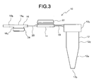
- FIG. 3 is a side view of the container with lid of FIG. 1;
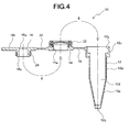
- FIG. 4 is a sectional view taken along line IV-IV of FIG. 2;
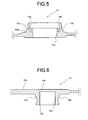
- FIG. 5 is an enlarged sectional view showing a first lid portion of the container with lid of FIG. 1;
- FIG. 6 is an enlarged sectional view showing a second lid portion of the container with lid of FIG. 1;
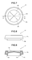
- FIG. 7 is an enlarged plan view of a first sealing member of the container with lid of FIG. 1;
- FIG. 8 is a side view of the first sealing member of FIG. 7;
- FIG. 9 is a sectional view taken along line IX-IX of FIG. 7;
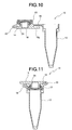
- FIG. 10 is a sectional view showing a state that the first lid portion of the container with lid of FIG. 1 is open while the second lid portion thereof is closed;
- FIG. 11 is a sectional view showing a state that the first and second lid portions of the container with lid of FIG. 1 are closed; and
- FIG. 12 is a sectional view showing a state that the second lid portion of the container with lid of FIG. 1 while the first lid portion thereof is closed.
- Referring now to the accompanying drawings, the preferred embodiment of a container with lid according to the present invention will be described below in detail.
- As shown in FIGS. 1 through 4, a
container 10 with lid in this preferred embodiment comprises: atubular container body 12 having a bottom at the lower end thereof and an opening 12a at the upper end thereof; afirst lid portion 14 for opening and closing the opening 12a of thecontainer body 12; asecond lid portion 16 for opening and closing an opening 14a which is formed in thefirst lid portion 14; a first connectingportion 18 which connects thecontainer body 12 with thefirst lid portion 14; and a second connectingportion 20 which connects thefirst lid portion 14 with thesecond lid portion 16. Thecontainer body 12,first lid portion 14,second lid portion 16, first connectingportion 18 and second connectingportion 20 are made of a flexible resin material, such as polypropylene, having excellent chemical resistance and heat resistance, and are integral-molded by injection molding or the like. Thecontainer 10 with lid in this preferred embodiment further comprises a first sealingmember 22 mounted on thefirst lid portion 14, and asecond sealing member 24 mounted on thesecond lid portion 16. - The
container body 12 comprises: a substantially cylindrical large-diameter portion 12c having a substantiallycircular opening 12a at the upper end thereof; a substantially cylindrical small-diameter portion 12d, the diameter of which is smaller than that of the large-diameter portion 12c; and atapered portion 12e having a substantiallycircular bottom portion 12b at the lower end thereof. The small-diameter portion 12d extends downwards from the bottom of the large-diameter portion 12c, and thetapered portion 12e extends downwards from the bottom of the small-diameter portion 12e, so that aliquid storing chamber 12f having a volume of about 0.5 to 1.5 ml is formed in thecontainer body 12. - The
first lid portion 14 comprises a substantially cylindrical member which has a substantiallycylindrical opening 14a. As shown in FIGS. 1 through 5, thefirst lid portion 14 has agroove portion 14b, which is formed in the top face thereof (the upper surface in FIG. 5) and which extends in circumferential directions so that acylindrical portion 22b (see FIG. 9) of the first sealing member 22 (which will be described later) is fitted into thegroove portion 14b, and agroove portion 14c which is formed in the side face thereof and which extends in circumferential directions so that anengaging portion 22c (see FIG. 9) of the first sealing member 22 (which will be described later) is fitted into thegroove portion 14c. Furthermore, the outside diameter of a portion of the first lid portion 14 (a cylindrical portion shown by 14d in FIG. 5), which is inserted into the opening 12a of thecontainer body 12 when thecontainer body 12 is closed by thefirst lid portion 14, is slightly smaller than the inside diameter of the opening 12a of thecontainer body 12. Thus, as shown in FIGS. 11 and 12, when thecontainer body 12 is closed by thefirst lid member 14, thecylindrical portion 14d of thefirst lid member 14 is housed in the opening 12a of thecontainer body 12, and thefirst sealing member 22 mounted on thefirst lid member 14 is compressed to seal the peripheral portion of the opening 12a of thecontainer body 12. - As shown in FIGS. 1 through 4 and 6, the
second lid member 16 comprises: a substantially guitar-shapedflat plate portion 16a having aprotruding portion 16b which extends from the side face of a substantially circular plate portion in substantially parallel thereto; and acylindrical portion 16c which extends downwards from the bottom face of the substantially circular plate portion of theflat plate portion 16a in substantially perpendicular thereto and which has a substantiallycircular opening 16d at the lower end thereof. The side face of thecylindrical portion 16c has agroove portion 16e which extends in circumferential directions and into which a substantially cylindricalsecond sealing member 24 of a softer material, such as a rubber, e.g. silicon rubber, than the resin material is fitted. Furthermore, the outside diameter of thecylindrical portion 16c of thesecond lid portion 16 is slightly smaller than the inside diameter of the opening 14a of thefirst lid member 14. Thus, when the opening 14a of thefirst lid portion 14 is closed by thesecond lid portion 16 as shown in FIGS. 10 and 11, thecylindrical portion 16c of thesecond lid portion 16 is housed in the opening 14a of thefirst lid portion 14, and thesecond sealing member 24 fitted into thegroove portion 16e of thesecond lid portion 16 is compressed to seal the opening 14a of thefirst lid member 14. - As shown in FIGS. 1 through 4, the first connecting
portion 18 comprises a strip-like portion which substantially linearly extends from a portion near the upper end of the side face of the large-diameter portion 12c of thecontainer body 12 to a portion near the lower end (the lower end in FIGS. 3 and 4) of the side face of thefirst lid portion 14 to connect thecontainer body 12 with thefirst lid portion 14. The central portion of the first connectingportion 18, except for both end portions thereof, is thin to such an extent that it can be folded as shown in FIGS. 11 and 12. Thus, the opening 12a of thecontainer body 12 can be closed by thefirst lid portion 14 as shown by arrow B in FIG. 4. - As shown in FIGS. 1 through 4, the second connecting
portion 20 comprises a strip-like portion substantially linearly extending from a portion near the lower end (the lower end in FIGS. 3 and 4) of the side face of thefirst lid portion 14, which is the opposite side face to the first connectingportion 18 in radial directions, to the side face of theflat plate portion 16a of thesecond lid portion 16, which is the opposite side face to the protrudingportion 16b. The central portion of the second connectingportion 20, except for both end portions thereof, is thin to such an extent that it can be folded as shown in FIGS. 10 and 11. Thus, the opening 14a of thefirst lid portion 14 can be closed by thesecond lid portion 16 as shown by arrow A in FIG. 4. - The first sealing
member 22 is made of a softer material, such as a rubber, e.g. silicon rubber, than the resin material. As shown in FIGS. 7 through 9, thefirst sealing member 22 comprises acylindrical portion 22b having a substantiallycircular opening 22a, anengaging portion 22c protruding and extending from thecylindrical portion 22b, and a closing portion for opening and closing the opening 22a of thecylindrical portion 22b. Theengaging portion 22c protrudes outwards in radial directions from the upper end of the side face of thecylindrical portion 22b. Theengaging portion 22c extends so as to have a substantially U-shaped cross section to form agap 22e between the tip thereof and thecylindrical portion 22b, and extends over the entire periphery of thecylindrical portion 22b in circumferential directions thereof. Thecylindrical portion 22b of thefirst sealing member 22 is fitted into thegroove portion 14b which is formed in the top face of the first lid portion 14 (the upper surface in FIG. 5), and the tip portion of theengaging portion 22c is fitted into thegroove portion 14c which is formed in the side face of thefirst lid portion 14. Thus, thefirst lid member 14 is clamped and held between thecylindrical portion 22b and theengaging portion 22c, so that thefirst sealing member 22 is fixed to thefirst lid member 14. Theclosing portion 22d comprises a substantially plate-like portion which is slightly inclined upwards as a distance from the center thereof decreases. Theclosing portion 22d has across-shaped cut 22f which is made therein so as to cross at the center thereof as shown in FIG. 7, so that a pipette chip or like can be inserted into thecontainer body 12 through thecut 22f to pipette a liquid from thecontainer body 12 even if the opening 12a of thecontainer body 12 is closed by thefirst lid portion 14 as shown in FIG. 12. - Referring to FIGS. 10 through 12, an example of a method for using the
container 10 with lid in this preferred embodiment will be described below. - First, as shown in FIG. 10, the
first lid portion 14 of thecontainer 10 with lid is open while thesecond lid portion 16 thereof is closed. In this state, a liquid, such as a reagent, is put in thecontainer body 12. Then, as shown in FIG. 11, thefirst lid portion 14 is closed. In this state, theopening 12a of thecontainer body 12 is air-tightly closed by the first sealingmember 22 which is mounted on thefirst lid portion 14, and theopening 14a of thefirst lid portion 14 is air-tightly closed by the second sealingmember 24 which is mounted on thesecond lid portion 16, so that the interior of thecontainer body 12 can be held in a sealed state. If a liquid, such as a reagent, is thus put in thecontainer body 12 in a state that theopening 14a of thefirst lid portion 14 is closed by thesecond lid portion 16, the interior of thecontainer body 12 can be held in a sealed state by closing thefirst lid portion 14 without causing the operator's hand to contact theopening 14a of thefirst lid portion 14 and theclosing portion 22d of the first sealingmember 22, so that it is possible to prevent contamination of the liquid in thecontainer body 12. - Then, as shown in FIG. 12, the
second lid portion 16 of thecontainer 10 with lid is open while thefirst lid portion 14 thereof is closed. In this state, a pipette or the like can be inserted into thecontainer body 12 through thecross-shaped cut 22f to pipette the liquid from thecontainer body 12 while the interior of thecontainer body 12 is substantially held in a sealed state without substantially opening the interior of thecontainer body 12, since thecross-shaped cut 22f is made in theclosing portion 22d of the first sealingmember 22 although the peripheral portion of theopening 12a of thecontainer body 12 is sealed by the first sealingmember 22 which is mounted on thefirst lid portion 14. Therefore, even if a liquid, such as a volatile reagent, is held in thecontainer body 12, it is possible to hold gastightness in thecontainer body 12 to prevent evaporation in thecontainer body 12. In addition, the opening and closing directions of thefirst lid portion 14 are opposite to those of thesecond lid portion 16, and thesecond lid portion 16 has the protrudingportion 16b, so that it is possible to simply open and close thefirst lid portion 14 andsecond lid portion 16 by the operator's one hand. - While the large-
diameter portion 12c of thecontainer body 12, thefirst lid portion 14 and thesecond lid portion 14 in thecontainer 10 with lid have been substantially linearly arranged in the above-described preferred embodiment, it is not always required to substantially linearly arrange them if they are integral-molded. - While the first sealing
member 22 has been mounted on thefirst lid portion 14 of thecontainer 10 with lid in the above-described preferred embodiment, it is not required to provide the first sealingmember 22 if thefirst lid portion 14 has a shape corresponding to the first sealingmember 22 mounted thereon while a soft material is used as the material of thecontainer body 12 and so forth to be integral-molded. Alternatively, it is not required to provide the first sealingmember 22 if a closing portion corresponding to theclosing portion 22d of the first sealingmember 22 is formed so as to be integrated with thefirst lid portion 14 and if the outside diameter of a portion (thecylindrical portion 14d) of thefirst lid portion 14 to be inserted into theopening 12a of thecontainer body 12 is increased so that thecylindrical portion 14d of thefirst lid portion 14 can be fitted into theopening 12a of thecontainer body 12 to seal the peripheral portion of theopening 12a of thecontainer body 12 when theopening 12a of thecontainer body 12 is closed by thefirst lid portion 14, while a soft material is used as the material of thecontainer body 12 and so forth to be integral-molded. Also in such constructions, it is possible to prevent evaporation of a liquid, such as a reagent, in thecontainer body 12 when the liquid is pipetted by means of a pipette chip. - Similarly, while the second sealing
member 24 has been mounted on thesecond lid portion 16 of thecontainer 10 with lid in the above-described preferred embodiment, it is not required to provide the second sealingmember 24 if thecylindrical portion 16c of thesecond lid portion 16 has a shape corresponding to the second sealingmember 24 mounted thereon while a soft material is used as the material of thecontainer body 12 and so forth to be integral-molded. Alternatively, it is not required to provide the second sealingmember 24 if the outside diameter of thecylindrical portion 16c of thesecond lid portion 16 is increased so that thecylindrical portion 16c of thesecond lid portion 16 can be fitted into theopening 14a of thefirst lid portion 14 to seal theopening 14a of thefirst lid portion 14 when theopening 14a of thefirst lid portion 14 is closed by thesecond lid portion 16, while a soft material is used as the material of thecontainer body 12 and so forth to be integral-molded. - A container with lid according to the present invention can be utilized as a microcentrifuge tube in various fields of biochemistry, such as genetic engineering, cell culture and pharmacological evaluation, and can be utilized as one of various containers, such as sampling containers, assaying containers, reaction containers and centrifuge containers.
Claims (7)
- A container with lid comprising:a tubular container body having a bottom at one end thereof and having an opening at the other end thereof;a first lid portion capable of opening and closing the opening of the container body;a second lid portion capable of opening and closing an opening which is formed in the first lid portion;a first connecting portion which connects the first lid portion with the container body; anda second connecting portion which connects the second lid portion with the first lid portion,wherein the container body, the first and second lid portions, and the first and second connecting portions are integral-molded.
- A container with lid as set forth in claim 1, which further comprises a first sealing member, mounted on said first lid portion, for sealing a gap between a peripheral portion of said first lid portion and the opening of said container body when the opening of said container body is closed by said first lid portion.
- A container with lid as set forth in claim 2, wherein said first sealing member has a closing portion capable of opening and closing a central portion of the opening of said first lid portion.
- A container with lid as set forth in claim 3, wherein said closing portion has a cut.
- A container with lid as set forth in claim 1, which further comprises a second sealing member, mounted on said second lid portion, for sealing a gap between said second lid portion and the opening of said first lid portion when the opening of said first lid portion is closed by said second lid portion.
- A container with lid as set forth in claim 1, wherein said first connecting portion is folded when the opening of said container body is closed by said first lid portion, and said second connecting portion is folded when the opening of said first lid portion is closed by said second lid portion.
- A container with lid as set forth in claim 1, wherein said container body, said first and second lid portions, and said first and second connecting portions are made of a resin material, and said first and second sealing members are made of a material which is softer than said resin material.
Applications Claiming Priority (1)
| Application Number | Priority Date | Filing Date | Title |
|---|---|---|---|
| JP2006312947A JP2008128776A (en) | 2006-11-20 | 2006-11-20 | Container with lid |
Publications (1)
| Publication Number | Publication Date |
|---|---|
| EP1923136A1 true EP1923136A1 (en) | 2008-05-21 |
Family
ID=39020758
Family Applications (1)
| Application Number | Title | Priority Date | Filing Date |
|---|---|---|---|
| EP07022241A Withdrawn EP1923136A1 (en) | 2006-11-20 | 2007-11-15 | Container with lid |
Country Status (3)
| Country | Link |
|---|---|
| US (1) | US20080116204A1 (en) |
| EP (1) | EP1923136A1 (en) |
| JP (1) | JP2008128776A (en) |
Cited By (4)
| Publication number | Priority date | Publication date | Assignee | Title |
|---|---|---|---|---|
| CN104399543A (en) * | 2014-11-30 | 2015-03-11 | 浙江硕华医用塑料有限公司 | Microcentrifuge tube with easily flipped cover |
| CN104907111A (en) * | 2014-03-14 | 2015-09-16 | 无锡市凯顺医疗器械制造有限公司 | Convenient leakproof liquid storage device and leakproof method thereof |
| WO2020231474A3 (en) * | 2018-12-17 | 2021-03-11 | Sio2 Medical Products, Inc. | Container and cap assembly for cryogenic storage |
| WO2021186361A1 (en) * | 2020-03-17 | 2021-09-23 | Diagnostics For The Real World, Ltd | Sample collection device |
Families Citing this family (20)
| Publication number | Priority date | Publication date | Assignee | Title |
|---|---|---|---|---|
| FR2928632B1 (en) * | 2008-03-11 | 2012-06-01 | Imagene | CONTAINER FOR RECEIVING AND RETAINING BIOLOGICAL MATERIAL, IN PARTICULAR DNA |
| CA2662546A1 (en) * | 2009-04-15 | 2010-10-15 | Spartan Bioscience Inc. | Tube for dna reactions |
| US20150048110A1 (en) * | 2013-08-15 | 2015-02-19 | Paul dePOO | Coconut Valve |
| US10548342B2 (en) | 2010-06-03 | 2020-02-04 | Paul dePOO | Resealable spout for selectively accessing coconut water within a coconut |
| WO2013022439A1 (en) * | 2011-08-09 | 2013-02-14 | Depoo Paul | Resealable spout for selectively accessing coconut water within a coconut |
| IT1400443B1 (en) * | 2010-06-08 | 2013-05-31 | Lizzio | CONTAINER FOR HOT FOOD AND ITS LID. |
| USD708944S1 (en) * | 2011-09-12 | 2014-07-15 | Save-Ty Can Cap B.V. | Can cap |
| USD708943S1 (en) * | 2012-03-12 | 2014-07-15 | Save-Ty Can Cap B.V | Can cap |
| USD730730S1 (en) * | 2013-01-18 | 2015-06-02 | Vinum Corporation | Reusable bottle stopper |
| US11345525B2 (en) | 2013-03-15 | 2022-05-31 | Cepheid | Multi-chambered lid apparatus with reagent port |
| ES2705243T3 (en) | 2013-03-15 | 2019-03-22 | Cepheid | Multi-chamber cover device |
| CN108341155B (en) * | 2018-01-31 | 2024-07-30 | 深圳迎凯生物科技有限公司 | Container cover |
| CN110124764A (en) * | 2019-05-30 | 2019-08-16 | 天津国科医工科技发展有限公司 | Reagent evaporation retardation device and its suppressing method for fully automatic liquid processing |
| CN112237950A (en) * | 2019-07-19 | 2021-01-19 | 北京陆桥技术股份有限公司 | Test tube cover |
| US12054320B2 (en) | 2019-09-23 | 2024-08-06 | Cepheid | Multi-chambered lid apparatus with reagent port |
| ES2984742T3 (en) * | 2020-08-24 | 2024-10-30 | Hoffmann La Roche | Reagent container lid, reagent container unit and reagent kit |
| USD987849S1 (en) | 2020-08-24 | 2023-05-30 | Roche Diagnostics Operations, Inc. | Holder and storage device for reagent tubes |
| USD997382S1 (en) | 2021-02-22 | 2023-08-29 | Roche Diagnostics Operations, Inc. | Component of a holder and storage device for reagent tubes |
| US20250058943A1 (en) * | 2023-08-14 | 2025-02-20 | Rtic Outdoors, Llc | Lid |
| CN119018479A (en) * | 2024-08-27 | 2024-11-26 | 上海洁士鼎医用新材料有限公司 | Anti-pollution sealed bottle cap |
Citations (6)
| Publication number | Priority date | Publication date | Assignee | Title |
|---|---|---|---|---|
| US4132225A (en) * | 1976-11-18 | 1979-01-02 | Hynson, Westcott & Dunning, Inc. | Micro blood collector |
| FR2625691A1 (en) * | 1988-01-13 | 1989-07-13 | Diekmann Stephan | A CENTRIFUGEABLE COUPLING OR REACTION COLUMN ASSEMBLY |
| DE9006079U1 (en) * | 1990-05-30 | 1990-09-13 | Bethkenhagen, Jürgen, 5223 Nümbrecht | Lid |
| WO1994002374A1 (en) * | 1992-07-20 | 1994-02-03 | Innervision, Inc. | Multiple cap seal for containers |
| DE10340538A1 (en) * | 2003-09-03 | 2005-04-07 | Kabe-Labortechnik Gmbh | Tube to hold fluid samples for medical analysis, in an automated system where a needle extracts the sample, has a stopper with an outer cylindrical seal and an inner rubber insert for protection against contamination and infection |
| DE202005010315U1 (en) * | 2005-06-30 | 2005-09-15 | Bartec Gmbh | Sample holder, for a milk sample to be sent for analysis, has an integrated closure lid with an injection opening and a tamper-proof security lid to prevent manipulation |
Family Cites Families (1)
| Publication number | Priority date | Publication date | Assignee | Title |
|---|---|---|---|---|
| US3587944A (en) * | 1968-10-07 | 1971-06-28 | Harold T Pehr | Dispensers with integral removable closures |
-
2006
- 2006-11-20 JP JP2006312947A patent/JP2008128776A/en not_active Withdrawn
-
2007
- 2007-11-14 US US11/985,134 patent/US20080116204A1/en not_active Abandoned
- 2007-11-15 EP EP07022241A patent/EP1923136A1/en not_active Withdrawn
Patent Citations (6)
| Publication number | Priority date | Publication date | Assignee | Title |
|---|---|---|---|---|
| US4132225A (en) * | 1976-11-18 | 1979-01-02 | Hynson, Westcott & Dunning, Inc. | Micro blood collector |
| FR2625691A1 (en) * | 1988-01-13 | 1989-07-13 | Diekmann Stephan | A CENTRIFUGEABLE COUPLING OR REACTION COLUMN ASSEMBLY |
| DE9006079U1 (en) * | 1990-05-30 | 1990-09-13 | Bethkenhagen, Jürgen, 5223 Nümbrecht | Lid |
| WO1994002374A1 (en) * | 1992-07-20 | 1994-02-03 | Innervision, Inc. | Multiple cap seal for containers |
| DE10340538A1 (en) * | 2003-09-03 | 2005-04-07 | Kabe-Labortechnik Gmbh | Tube to hold fluid samples for medical analysis, in an automated system where a needle extracts the sample, has a stopper with an outer cylindrical seal and an inner rubber insert for protection against contamination and infection |
| DE202005010315U1 (en) * | 2005-06-30 | 2005-09-15 | Bartec Gmbh | Sample holder, for a milk sample to be sent for analysis, has an integrated closure lid with an injection opening and a tamper-proof security lid to prevent manipulation |
Cited By (6)
| Publication number | Priority date | Publication date | Assignee | Title |
|---|---|---|---|---|
| CN104907111A (en) * | 2014-03-14 | 2015-09-16 | 无锡市凯顺医疗器械制造有限公司 | Convenient leakproof liquid storage device and leakproof method thereof |
| CN104399543A (en) * | 2014-11-30 | 2015-03-11 | 浙江硕华医用塑料有限公司 | Microcentrifuge tube with easily flipped cover |
| CN104399543B (en) * | 2014-11-30 | 2016-08-24 | 浙江硕华生命科学研究股份有限公司 | Easily renovate microcentrifugal tube |
| WO2020231474A3 (en) * | 2018-12-17 | 2021-03-11 | Sio2 Medical Products, Inc. | Container and cap assembly for cryogenic storage |
| US12528084B2 (en) | 2018-12-17 | 2026-01-20 | Sio2 Medical Products, Llc | Container and cap assembly for cryogenic storage |
| WO2021186361A1 (en) * | 2020-03-17 | 2021-09-23 | Diagnostics For The Real World, Ltd | Sample collection device |
Also Published As
| Publication number | Publication date |
|---|---|
| US20080116204A1 (en) | 2008-05-22 |
| JP2008128776A (en) | 2008-06-05 |
Similar Documents
| Publication | Publication Date | Title |
|---|---|---|
| US20080116204A1 (en) | Container with lid | |
| US8387810B2 (en) | Pierceable cap having piercing extensions for a sample container | |
| US8387811B2 (en) | Pierceable cap having piercing extensions | |
| US5846489A (en) | System for opening closures of vessels and for the contamination-free operation of reaction sequences | |
| US8491499B2 (en) | Biological fluid sampling and pretreating system and a method thereof | |
| CN103068485B (en) | The sealing of the reaction tube of analyzing for bioaffinity | |
| US11325116B2 (en) | Tip set | |
| US20090257922A1 (en) | Penetratable Septum Cap | |
| EP1707267A1 (en) | Device having a self sealing fluid port | |
| US20060171851A1 (en) | Liquid sampling utilizing ribbed pipette tip for barrier penetration | |
| JP5430766B2 (en) | Chip card plate for biochemical analysis and method of use thereof | |
| US9829416B2 (en) | Closure with septum strip | |
| CN101398437A (en) | Liquid transfer device and liquid transfer tube and series container used in same | |
| JP3142126U (en) | Droplet storage device | |
| WO2010042690A1 (en) | Devices for containing materials and methods of using and making same | |
| CN111348330A (en) | Pressure-tight storage container containing a liquid | |
| EP2415524A2 (en) | Sealed Device | |
| JP2008064554A (en) | Sample container adapter and sample container rack | |
| JP3142125U (en) | container | |
| EP4599932A1 (en) | Kit for mixing different types of materials | |
| JP2007046998A (en) | Chemical analyzer and reagent device used therefor | |
| JP2026058332A (en) | Specimen container holding device and kit equipped with the device | |
| JP2001161342A (en) | Holding base for microtube | |
| KR20220066392A (en) | Multi-chamber lid instrument with reagent ports |
Legal Events
| Date | Code | Title | Description |
|---|---|---|---|
| PUAI | Public reference made under article 153(3) epc to a published international application that has entered the european phase |
Free format text: ORIGINAL CODE: 0009012 |
|
| AK | Designated contracting states |
Kind code of ref document: A1 Designated state(s): AT BE BG CH CY CZ DE DK EE ES FI FR GB GR HU IE IS IT LI LT LU LV MC MT NL PL PT RO SE SI SK TR |
|
| AX | Request for extension of the european patent |
Extension state: AL BA HR MK RS |
|
| RIN1 | Information on inventor provided before grant (corrected) |
Inventor name: OHSE, TAKUHITO |
|
| 17P | Request for examination filed |
Effective date: 20081028 |
|
| 17Q | First examination report despatched |
Effective date: 20081125 |
|
| AKX | Designation fees paid |
Designated state(s): AT BE BG CH CY CZ DE DK EE ES FI FR GB GR HU IE IS IT LI LT LU LV MC MT NL PL PT RO SE SI SK TR |
|
| STAA | Information on the status of an ep patent application or granted ep patent |
Free format text: STATUS: THE APPLICATION IS DEEMED TO BE WITHDRAWN |
|
| 18D | Application deemed to be withdrawn |
Effective date: 20090606 |