EP1922701B1 - Triangulationsverfahren für eine oberfläche eines physischen objekts - Google Patents
Triangulationsverfahren für eine oberfläche eines physischen objekts Download PDFInfo
- Publication number
- EP1922701B1 EP1922701B1 EP06795675A EP06795675A EP1922701B1 EP 1922701 B1 EP1922701 B1 EP 1922701B1 EP 06795675 A EP06795675 A EP 06795675A EP 06795675 A EP06795675 A EP 06795675A EP 1922701 B1 EP1922701 B1 EP 1922701B1
- Authority
- EP
- European Patent Office
- Prior art keywords
- triangulation
- point
- junction
- mesh representation
- polygon
- Prior art date
- Legal status (The legal status is an assumption and is not a legal conclusion. Google has not performed a legal analysis and makes no representation as to the accuracy of the status listed.)
- Active
Links
Images


Classifications
-
- G—PHYSICS
- G06—COMPUTING OR CALCULATING; COUNTING
- G06T—IMAGE DATA PROCESSING OR GENERATION, IN GENERAL
- G06T17/00—Three-dimensional [3D] modelling for computer graphics
- G06T17/20—Finite element generation, e.g. wire-frame surface description, tesselation
-
- G—PHYSICS
- G06—COMPUTING OR CALCULATING; COUNTING
- G06T—IMAGE DATA PROCESSING OR GENERATION, IN GENERAL
- G06T17/00—Three-dimensional [3D] modelling for computer graphics
- G06T17/20—Finite element generation, e.g. wire-frame surface description, tesselation
- G06T17/205—Re-meshing
Definitions
- the invention relates to the field of triangulation methods.
- the invention relates to a triangulation method of multiple objects with common boundaries in labelled 3D images.
- the invention further relates to a system, a computer readable medium, a computer program product, an image acquisition device and an image workstation designed to perform such a triangulation method.
- Geometrical surface-models of anatomical structures are commonly represented by three-dimensional (3D) triangular surface meshes.
- 3D triangular surface mesh representation of an object generally works well in case that the dataset from which the surfaces mesh is reconstructed represents a 2-manifold, i.e. can be divided into voxels lying "inside” or "outside” of the object.
- a triangle of the 3D surface mesh may have more than three neighbouring triangles, in particular in areas where surfaces of the objects form so called 3D T-junction, i.e. a junction where two or more different objects meet each other.
- 3D T-junction i.e. a junction where two or more different objects meet each other.
- image features are ambiguous and lead to segmentation errors when the 3D triangular surface mesh is constructed.
- Image segmentation using so called deformable models are an important technology in medical applications.
- This technique can provide shape information of the single objects adjacent to each other, thus reducing ambiguity in the image content and leading to more robust segmentation results.
- Typical shapes of organs are often represented by triangular surface meshes.
- the robustness of these methods can be improved by adding information about special relationships of multiple objects. For example, the adding can be done by representing multiple objects with common or touching boundaries with a single mesh structure.
- segment mid-points are generated if the labels of two adjacent so-called voxels (volume pixels) are different. For each generated segment mid-point a new segment (line) to the cell mid-point is generated. The same strategy of inserting additional cell mid-points can be used for the 3D case.
- An exemplary embodiment of the invention provides a method for producing a triangulation of a surface of a physical object the method comprising the steps of generating an intermediate mesh representation of the surface out of surface voxels and detecting at least one T-junction in the intermediate mesh representation. The method further comprising the steps of decomposing the at least one T-junction into at least one triangle and at least one two-point-polygon, and generating the triangulation of the surface out of the modelled intermediate mesh representation.
- a T-junction is an occurrence where more than two polygons share a common edge.
- the T-junction may be decomposed by detaching the polygons from each other, replacing the common edge by a 2-point-polygon/line segment and attaching the polygons to the newly created 2-point-polygons.
- the connected sets of 2-point-polygons may form seams between the different surfaces.
- an exemplary embodiment relates to a system for producing a triangulation of a surface of a physical object
- the system comprises a processor which is adapted to perform the following method steps generating an intermediate mesh representation of the surface out of surface voxels, detecting at least one T-junction in the intermediate mesh representation, decomposing the at least one T-junction into at least one triangle and at least one two-point-polygon, and generating the triangulation of the surface out of the modelled intermediate mesh representation.
- an exemplary embodiment relates to a computer readable medium in which a program for producing a triangulation of a surface of a physical object is stored which program comprises the following method steps, if executed by a processor. Generating an intermediate mesh representation of the surface out of surface voxels, detecting at least one T-junction in the intermediate mesh representation, decomposing the at least one T-junction into at least one triangle and at least one two-point-polygon, and generating the triangulation of the surface out of the modelled intermediate mesh representation.
- an exemplary embodiment relates to a computer program product for producing a triangulation of a surface of a physical object
- the computer program product comprises the following method steps if executed by a processor generating an intermediate mesh representation of the surface out of surface voxels, detecting at least one T-junction in the intermediate mesh representation, decomposing the at least one T-junction into at least one triangle and at least one two-point-polygon, and generating the triangulation of the surface out of the modelled intermediate mesh representation.
- the present invention may provide for a method for triangulation of a physical object, e.g. for a triangulation of human organs.
- Triangulation according to this application means the construction of a three-dimensional mesh of triangles that represent a surface of the physical object.
- the triangulation can be determined out of so called voxels, i.e. volume pixels, which can be determined by tomographic methods like Computer Tomography, Magnetic Resonance Imaging or Positron Emission Tomography.
- a characteristic feature according to the present invention may be that so called T-junctions, i.e. areas where two or more objects touch each other and triangles of the triangulation of the surface would have more than three neighbouring triangles, are decomposed into sets of triangles and 2-point-polygons.
- T-junction describes the fact that some triangles are part of a surface that have more than one adjacent surface. That is a T-junction is an area where surfaces of different objects touching each other, like a surface where different humans organs laying next to each other, i.e. having one common boundary.
- Such T-junctions lead to non-2-manifold surface meshes that are difficult to handle using ordinary triangulation methods.
- the decomposing of the T-junction may ensure that surface parts belonging to different human organs are only connected via those 2-point-polygons, such that the 2-manifold-condition, i.e. always three neighbours per triangle, may hold true for each surface part.
- the characteristic features according to the invention may have particularly the advantage that the decomposition of T-junctions into triangles and 2-point-polygons can be carried out so that the 2-manifold condition can hold true.
- a basic assumption of triangulation i.e. every triangle has exactly three adjacent triangles, may be preserved and basic features of common triangulation methods may be used.
- standard triangulation methods may be used.
- the method further comprises the step of decomposing more than two two-point-polygons which meet at a common vertex by inserting a one-point-polygon.
- T-junction After the decomposing of the at least one T-junction into at least one triangle and at least one two-point-polygon it can occur that a second type of T-junction occurs when more than two 2-point-polygons meet at a common voxel/vertex.
- These occurrences of T-junctions may be decomposed by detaching the 2-point-polygons from each other, inserting a 1-point-polygon at the vertex and connecting the 2-point-polygons to the newly created 1-point-polygon.
- the physical object comprises at least two distinct sections
- the method further comprising the step of labelling at least some of the surface voxels prior to generating the intermediate mesh representation the labelling representing the belonging of each labelled surface voxel to one of the at least two distinct sections.
- the method further comprising the step of connecting at least one pair of adjacent voxels having different labels by a two-point-polygon and/or a one-point-polygon during the decomposing.
- the method further comprising the step of connecting each pair of adjacent voxels having different labels by a two-point-polygon and/or a one-point-polygon.
- T-junctions e.g. T-junctions connected to multiple organs
- T-junctions are associated with a correct subset of neighbouring surface labels, e.g. each T-junction is associated with the correct subset of neighbouring organs.
- this associating is done before decomposing the T-junctions.
- the method further comprising the step of region growing after decomposing of the at least one T-junction.
- region growing By using region growing the number of voxels can be reduced which may lead to a faster generation of the triangulation of the surface of a physical object and to a significant reduction of triangles while preserving the accuracy of the triangular representation.
- the region growing may be implemented by a selection of vertices from the intermediate mesh representation the so-called micro mesh.
- the region growing is done by using a local curvature-adaptive thinning process.
- a local curvature-adaptive thinning process e.g. a process in which some vertices are selected leading to a resizing of the voxels, is depending on the local curvature of the object which shall be depicted by the triangulation, it may be possible to ensure that loss of information on the surface structure is minimized while the number of voxels is considerable reduced.
- the region growing is adapted so that no voxel having one label is shifted into a surface region comprising voxels of another label.
- the intermediate mesh representation comprises triangles and boundary edges and the region growing is adapted so that regions starting from boundary polygons may only grow along boundary polygons and regions starting from surface polygons may only grow into surface polygons.
- the generation of the triangulation is done by Delaunay-Triangulation.
- the triangulation is done by a Delaunay-Triangulation from the Voronoi-graph which is determined by the voxels.
- the method further comprising the step of correcting an orientation of triangles associated with the at least one T-junction.
- orientations which may be not well defined after generating the triangulation, are correctly shown in the generated image.
- the correcting can be done by using the orientation of neighbouring triangles.
- One aspect of the present invention might be seen in decomposing T-junctions into triangles and two-point-polygons and one-point-polygons so that standard triangulation methods can be used, because the 2-manifold condition can be met.
- the present invention may be of particular interest in the field of medical uses, e.g. in imaging of surfaces of physical objects, in particular in imaging organs of human beings by using voxel representation obtained by tomographic imaging.
- the present invention may be implemented in the medical image post-processing, e.g. in software products containing model-based segmentation algorithms.
- a method of producing a triangulation of a surface of a physical object comprises the step of labelling voxels 101.
- the labelling may be used to determine which voxels belonging to which part of the physical object, e.g. to which organ, when the physical object represents a number of organs scanned by a tomography.
- an intermediate mesh representation, a so called micro mesh, of the surface of the physical object is generated 102, wherein the surface is preferably defined by all surface voxels.
- the generation may be done by standard methods, for example according to the method described in " Computing curvature-adaptive surface triangulations of three-dimensional image data", N. Krahnstoever, C. Lorenz, in “The Visual Computer” (2004) page 17 to 35 and implemented herein by reference. In particular, the method that can be used is described in chapter 2 on pages 19 to 24.
- T-junctions are detected 103, e.g. areas of the surface of the micro mesh where two or more organs touch each other and triangles of the generated triangulation would have more than three neighbouring triangles.
- Such T-junctions may lead to segmentation faults when a Delaunay-Triangulation of the respective physical object is generated out of a Voronoi-graph.
- the detected T-junctions are modelled by 2-point-polygons 104. Thereby, the T-junctions may be decomposed into sets of triangles and 2-point-polygons. While doing this decomposition it may be ensured that surface parts of different labelling, e.g.
- multiple connected T-junctions e.g. T-junctions connected to multiple organs
- T-junctions are associated with an correct subset of neighbouring surface labels, e.g. each T-junction is associated with the correct subset of neighbouring organs.
- this associating is done before decomposing the T-junctions. By using such an associating step it may be ensured to obtain afterwards a correct Delaunay-Triangulation from the Voronoi-graph.
- vertices from the micro mesh may be selected according to a so called thinning process.
- the thinning process is a local curvature-adaptive thinning process as described for example in above mentioned “ Computing curvature-adaptive surface triangulations of three-dimensional image data", N. Krahnstoever, C. Lorenz, in “The Visual Computer” (2004), pages 17 to 35 , wherein the curvature-adaptive thinning is in particular described in chapter 3, on pages 24 to 28.
- the number of vertices or with other words the number of surface voxels, is reduced on which vertices a discrete approximation of the Voronoi-graph on the surface of the physical object is based on. From this discrete approximation of the Voronoi-graph its dual the surface Delaunay-Triangulation can be generated.
- the local curvature-adaptive thinning process the local shape of the physical object is incorporated in an early stage of the algorithm yielding an elegant method for obtaining shape-adaptive triangular meshes.
- the thinning corresponds to a growing of the surface regions which are represented by the voxels.
- One surface region is represented by substantially all adjacent surface voxels having substantially the same outer surface orientation, i.e. can be approximated by a single triangle, without loosing a great amount of information. The loosing of information is thereby dependent on the rate of the thinning.
- the region growing is modified so that no vertex that is labelled with a first label is shifted into a region in which vertices having a different second label.
- the region growing preferably is adapted so that no vertex that is part of a triangle is shifted to a boundary edge of the boundary edge, or vice versa, i.e. no vertex that is part of a boundary edge is shifted to a triangle.
- the selected vertices are used to generate the Voronoi-graph 106 from which the Delaunay-Triangulation can be obtained 107.
- a further step of correcting orientations of triangles which are associated with decomposed T-junctions may be implemented.
- the correcting can be made from the orientation of neighbouring triangles.
- the triangulation process may be divided into four major tasks, which will be described later in more detail:
- the cleaning of the source image is illustrated in the case of a two-dimensional (2x2)-slice and a three-dimensional (2x2x2)-volume.
- the cleaning of the source image means that the source image is changed so that some voxel configurations do not occur in the input voxel image.
- the two configurations, two-dimensional and three-dimensional case, have to be extended to all mirrored and rotated variants of all three dimensions.
- the two-dimensional (2x2)-slice is filled with max(a, ⁇ !a ⁇ ), i.e. all voxels of the slice are labelled with that label which is most frequent in the (2x2)-slice, when a (2x2)-violation occurs.
- the (2x2x2)-block is filled also with max(a, ⁇ !a ⁇ ), i.e. that label which is most frequent in the (2x2x2)-volume. This process is repeated until no more violations occur.
- micro mesh is the union of all surfaces that separate two voxels of different label in the source image and comprises a plurality of polygons each having a face.
- This micro mesh is the intermediate representation for the algorithm of the triangulation process to operate on.
- the following steps are performed on the micro mesh.
- a first step the connectivity of the polygons of the micro mesh is calculated, wherein vertices of the micro mesh know all faces that are connected to them and faces know about their neighbouring faces as well as the vertices that makes up the polygon. Thus the connectivity can be determined.
- two-point-polygons are added so that neighbouring triangles/polygons of different label are separated from each other by two-point-polygons. These two-point-polygons have no individual label and the label is preferably set to -1.
- one-point-polygons are added. This adding is carried out if more than two two-point-polygons meet at a vertex. In this case a one-point-polygon is inserted at this vertex separating the meeting two-point-polygons from each other. Two-point-polygons as well as one-point-polygons can be referred to as separators.
- the curvature is calculated.
- R represents the so-called elimination radius and can be set to a default value, e.g. to 6 mm. It also could be estimated by a multiple, e.g. 6, of the average micro mesh edge length.
- the coordinates of face centers that are part of the patch are transformed so that the local surface normal of the patch points in positive z-direction.
- the local surface normal can be obtained by averaging over all face normals of the patch.
- the principal curvature radius is extracted by eigenvalue decomposition.
- the value of the principal curvature radius is referred to as the face curvature.
- the triangulation can be generated.
- an appropriate gamma is determined, wherein gamma is the so-called detail balance parameter.
- gamma can be understand as a parameter which determines how many details can be seen in the output mesh or final triangulation.
- TPC target polygon count
- the bisecting is carried out in an iterative way. The bisecting is performed a predetermined number of times, e.g.
- the bisecting is preferably truncated in case that the deviation of the achieved TPC to the predetermined TPC is less than a given percentage, e.g. less than 0.8%.
- the triangulation is not performed to achieve the correct output geometry also referred to as the macro mesh or the output mesh, but only to count the numbers of triangles that would have been created. By comparing this number with the predetermined TPC it can be derived whether the present gamma is appropriate or whether an further iteration has to be performed.
- R max and R min can be bounded between 0 mm and 50 mm.
- R max and R min a selection and thinning can be performed as a first phase of the triangulation.
- a first step all micro mesh faces are added to a so-called candidate queue (LocalFaceQueue). Then all one-point-polygons are selected from the queue.
- the micro mesh face which has the highest local curvature and which is left in the candidate queue is extracted and added to the selection. Starting from this face all faces are removed from the candidate queue which faces are located within a neighbourhood of range R. This step is called thinning. This step is repeated until the candidate queue is empty.
- the neighbourhood R can be defined by the so-called curvature mapping function and is restricted to the interval [R min , R max ], wherein R min describes the minimum elimination radius and R max describes the maximum elimination radius.
- thinning step R is preferably divided by 2 for a two-point-polygon because higher detail is needed in junction areas which are indicated by the existence of two-point-polygons. Furthermore, neighbourhood is preferably restricted to faces having the same label, i.e. thinning for junction faces and ordinary faces is performed independently.
- an adaptive refinement can be performed as the second phase of the triangulation.
- the adaptive refinement phase all selected faces become region seed points from which simultaneous region growing is performed until the entire surface is covered.
- the result of this region growing is the Voronoi-graph approximation.
- From this Voronoi-graph its dual the Delaunay-Triangulation can be created which represent the output mesh.
- the details of the Delaunay-Triangulation step will be described later.
- the triangulation is only performed to count the triangles, i.e. to determine the appropriate gamma, the triangulation is stopped at this stage and it is returned to the next iteration of the gamma determination procedure.
- some further steps are performed in the following.
- the first of these further steps is the calculation of the connectivity on the output mesh. This can be done in the same way as the calculation of the connectivity of the micro mesh in the creation of the micro mesh. Further, two-point-polygons are added the same way as by the creation of the micro mesh, i.e. neighbouring triangles of different labels are separated from each other by two-point-polygons. Furthermore, repair faces are searched for by a first method (method 1). For finding repair faces each triangle of the output mesh which triangle has not three neighbours is reported as broken, whereby separators, i.e. two-point-polygons and one-point-polygons, are counted as neighbours. Separators itself are never reported as broken. If a triangle is reported as broken, i.e. has been assigned a repair face candidate, the candidate is added to the repair face list.
- a smooth border faces substep is performed in which all ordinary surface vertices of the output mesh that connected via an edge to a junction vertex, undergo a centroid smooth. This is done in an iterative procedure while using a predetermined number of iteration, e.g. 100 iterations. Then the separators are removed from the macro mesh and the faces are reconnected at the label borders. Afterwards it is searched for repair faces according to a second method (method 2).
- Method 2 is similar to method 1, but has a different criteria for broken faces. If the normals of two neighbouring faces have a scalar product of less than - 0.95 they are considered as being broken. Alternatively, this criteria could possibley be replaced by a self-intersection-detection, which would be probably slower in computing but would guarantee the elimination of all self intersections.
- repair faces are found the generated mesh is returned as the output mesh of the triangulation, i.e. the method according to the exemplary embodiment of the invention is finished. If repair faces are found these faces are added to the face selection and the adaptive refinement is repeated, starting with the region growing.
- one attached face is arbitrarily selected as a repair face, whereby the selected face is not part of the face selection and whereby the selected face is not already selected as a repair face. If later on a result triangle gets associated with this micro mesh vertex and the triangle is reported as broken by the methods for finding repair faces (see under adaptive refinement), this face is added to the face selection of the selection step of the triangulation. If three or more regions are found at this vertex neighbourhood relations are established of those regions, wherein this time neighbourhood between ordinary faces and separators is allowed, and the RegionList is partitioned, which is explained afterwards in greater detail.
- one output polygon is created by connecting the region seed points of the contained regions, wherein the face centers of the region seed faces become the vertices of the output triangulation. If separators are involved at this micro mesh vertex, all associated output faces are marked as orientation ambiguous while the other output faces are properly aligned. It should be noted that if no output mesh is created, i.e. if only the appropriate gamma is determined, only the resulting triangles are counted.
- a first face is extracted from the FaceRegionList.
- the faces at the micro mesh vertex belonging to the region of the extracted face are counted. In case that the counted number plus the number of separators at the vertex is less than three, the extracted region is removed from the FaceRegionList and the partitioning is restarted at the first step.
- the largest patch of faces having the same surface label as the faces of the region of the extracted first face are determined, wherein the largest part preferably is not divided by separators. All faces being part of this path are added to a so-called subset. Furthermore, all separators bordering to this path are determined and if a one-point-polygon is part of the RegionList, it is added also to the subset.
- an arbitrary circular path is determined for the regions of the subset. This circular path represents one partition and all non-separator faces/regions of this path are removed from the FaceRegionList. If the FaceRegionList is not empty, the partitioning is restarted at the first step to obtain the other partitions.
- the triangulation process is divided into four major tasks:
- Ad 2 Creating Micro Mesh
- the micro mesh is the union of all surfaces that separate two voxels of different label in the source image. This is the intermediate representation for the algorithm to operate on.
- a + B * T ⁇ W ⁇ O _ L ⁇ A ⁇ B ⁇ E ⁇ L _ B ⁇ A ⁇ S ⁇ E T ⁇ W ⁇ O _ L ⁇ A ⁇ B ⁇ E ⁇ L _ B ⁇ A ⁇ S ⁇ E : 1000
- a surface patch of given radius R around that face is obtained by region growing.
- the coordinates of face centers that are part of the patch are transformed such that the local surface normal of the patch points in positive z-direction.
- the local surface normal is obtained by averaging over all face normals of the patch.
- R is set to 6 millimeters by default. It could also be estimated by average_micro_mesh_edge_length * 6.
- Triangulate is bisected to find an appropriate gamma , matching the given Target polygon count (TPC).
- Phase 1 Adaptive refinement
- curvature mapping function (curv -> R)
- Separators are counted as neighbours. Separators are never broken. If a broken face has been assigned a repair face candidate, the candidate is added to the repair face list.
- Vertices of both macro mesh and micro mesh know all faces that are connected to them. Faces know about their neighbouring faces and of course the vertices that make up the polygon.
- Neighbouring triangles of different label are separated from each other by 2-point-polygons.
- the 2-point-polygons have no individual label (label -1).
- n p ⁇ 1 - p ⁇ 0 ⁇ x ⁇ p ⁇ 2 - 0
- the reordered face lists may be stored in the faces at vertex list, for non-regular vertices there is more than one path such that it cannot be stored in a single list.
- Fig. 2 shows schematic examples of triangulations obtained according to an exemplar embodiment of the present invention, wherein Fig. 2a shows a Voronoi-graph and a Delaunay-Triangulation of a cube.
- the black dots represent the vertices selected by the thinning step and used to generate the triangulation.
- Each vertex corresponds to a region of the surface of the cube. These regions are depicted in different grayscales and represent the Voronoi-graph. From the Voronoi-graph the Delaunay-Triangulation can be obtained which is the dual of the Voronoi-graph and which is depicted as the black lines in Fig. 2a .
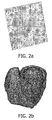
- Fig. 2b shows a triangulation of a more complex structure namely a triangulation of a heart.
- the black lines also represents the Delaunay-Triangulation.
- Fig. 2b the left and a right ventricle and a myocardium of a heart, can be seen.
- one aspect of the present invention can be seen in the decomposition of so called T-junctions into triangles and two-point-polygons, thus leading to the fact that the 2-manifold condition is met and consequently standard triangulation methods can be used.
- Fig. 3 shows the system according to the invention in a schematic way.
- a system 300 for producing a triangulation of a surface of a physical object comprises: a means 302 for generating an intermediate mesh representation of the surface out of surface voxels; a means 306 for detecting at least one T-junction in the intermediate mesh representation; a means 308 for decomposing of the at least one T-junction into at least one trangle and at least one two-point-polygon; a means 310 for generating the triangulation of the surface out of the modelled intermediate mesh representation.
- the system 300 further comprises a processor 312 and a software bus 314 that is designed to transport data between the means 302, 304, 306 and 310 and the processor 312 to enable the processor to perform the method steps according to the invention.
- the results of the intermediate method steps are shown to a user through display device 314. Alternatively only the end result, i.e. the triangulated sturcture is shown on display device 314.
- the system is connected to input and output devices through the interface means 316.
- This interface means 316 comprises interfacing means well known to a person skilled in the art to enable communication of the respective input and output devices with the system 300.
- the system 300 as described above can be part of an image acquisition device 318 like a Computed Tomography (CT) apparatus and/or an image workstation 320 further comprising input devices 322 like a mousepad or keypad, an output device, like the display device 314 and a computer station 324.
- CT Computed Tomography
- the enumerated means can be embodied by one and the same item of computer readable software or hardware.
- the invention can be implemented by means of hardware comprising several distinct elements, and by means of a suitably programmed computer.
Landscapes
- Physics & Mathematics (AREA)
- Engineering & Computer Science (AREA)
- Computer Graphics (AREA)
- Geometry (AREA)
- Software Systems (AREA)
- General Physics & Mathematics (AREA)
- Theoretical Computer Science (AREA)
- Image Generation (AREA)
- Processing Or Creating Images (AREA)
- Length Measuring Devices By Optical Means (AREA)
- Magnetic Resonance Imaging Apparatus (AREA)
- Image Processing (AREA)
- Application Of Or Painting With Fluid Materials (AREA)
Claims (16)
- Verfahren zur Erzeugung einer Triangulation einer Oberfläche eines physischen Objekts, wobei das Verfahren die folgenden Schritte umfasst:- Erzeugen einer Zwischen-Mesh-Darstellung der Oberfläche aus Oberflächenvoxeln (102),- Detektieren mindestens einer T-Kontaktstelle in der Zwischen-Mesh-Darstellung (103),- Zerlegen der mindestens einen T-Kontaktstelle in mindestens ein Dreieck und mindestens ein Zwei-Punkt-Polygon (104), und- Erzeugen der Triangulation der Oberfläche aus der modellierten Zwischen-Mesh-Darstellung (107).
- Verfahren nach Anspruch 1, weiterhin mit dem Schritt des Zerlegens von zwei Zwei-Punkt-Polygonen, die bei einem gemeinsamen Voxel aufeinander treffen, indem Ein-Punkt-Polygon eingefügt wird.
- Verfahren nach Anspruch 1 oder 2, wobei das physische Objekt mindestens zwei verschiedene Abschnitt umfasst, wobei das Verfahren weiterhin den Schritt des Kennzeichnens (101) mindestens einiger der Oberflächenvoxel vor dem Erzeugen der Zwischen-Mesh-Darstellung umfasst, wobei das Kennzeichnen die Zuordnung jedes gekennzeichneten Oberflächenvoxels zu einem der mindestens zwei verschiedenen Abschnitte darstellt.
- Verfahren nach Anspruch 3, wobei der Schritt des Zerlegens weiterhin den Teilschritt des Verbindens mindestens eines Paares benachbarter Voxel mit unterschiedlichen Kennzeichnungen durch ein Zwei-Punkt-Polygon und/oder ein Ein-Punkt-Polygon umfasst.
- Verfahren nach Anspruch 4, weiterhin mit dem Teilschritt des Verbindens jedes Paares benachbarter Voxel mit unterschiedlichen Kennzeichnungen durch ein Zwei-Punkt-Polygon und/oder ein Ein-Punkt-Polygon.
- Verfahren nach einem der Ansprüche 1 bis 5, weiterhin mit dem Schritt des Regionenwachstums (105) nach dem Zerlegen der mindestens einen T-Kontaktstelle.
- Verfahren nach Anspruch 6, wobei das Regionenwachstum durch Anwenden eines lokalen krümmungsadaptiven Verdünnungsprozesses erfolgt.
- Verfahren nach Anspruch 6 oder 7, wobei das Regionenwachstum so angepasst ist, dass kein Voxel mit einer Kennzeichnung in eine Oberflächenregion verschoben wird, die Voxel mit einer anderen Kennzeichnung umfasst.
- Verfahren nach einem der Ansprüche 6 bis 8, wobei die Zwischen-Mesh-Darstellung Dreiecke und Grenzlinien umfasst und wobei das Regionenwachstum so angepasst ist, dass kein zu einem Dreieck gehörendes Voxel zu einer Grenzlinie wird und dass kein Grenzlinienvoxel zu einem Dreieck wird.
- Verfahren nach einem der Ansprüche 1 bis 9, wobei die Erzeugung der Triangulation durch Delaunay-Triangulation erfolgt.
- Verfahren nach einem der Ansprüche 1 bis 10, weiterhin mit dem Schritt des Korrigierens der Ausrichtung von Dreiecken, die zu der mindestens einen T-Kontaktstelle gehören (108).
- System (300) zur Erzeugung einer Triangulation einer Oberfläche eines physischen Objekts, wobei das System einen Prozessor (312) umfasst, der vorgesehen ist, um die folgenden Verfahrensschritte durchzuführen:- Erzeugen einer Zwischen-Mesh-Darstellung der Oberfläche aus Oberflächenvoxeln (102),- Detektieren mindestens einer T-Kontaktstelle in der Zwischen-Mesh-Darstellung (103),- Zerlegen der mindestens einen T-Kontaktstelle in mindestens ein Dreieck und mindestens ein Zwei-Punkt-Polygon (104), und- Erzeugen der Triangulation der Oberfläche aus der modellierten Zwischen-Mesh-Darstellung (107).
- Computerlesbares Medium, auf dem ein Programm zum Erzeugen einer Triangulation einer Oberfläche eines physischen Objekts gespeichert ist, wobei das Programm die folgenden Verfahrensschritte umfasst, wenn es durch einen Prozessor (312) ausgeführt wird:- Erzeugen einer Zwischen-Mesh-Darstellung der Oberfläche aus Oberflächenvoxeln (102),- Detektieren mindestens einer T-Kontaktstelle in der Zwischen-Mesh-Darstellung (103),- Zerlegen der mindestens einen T-Kontaktstelle in mindestens ein Dreieck und mindestens ein Zwei-Punkt-Polygon (104), und- Erzeugen der Triangulation der Oberfläche aus der modellierten Zwischen-Mesh-Darstellung (107).
- Computerprogrammprodukt (302, 306, 308, 310) zum Erzeugen einer Triangulation einer Oberfläche eines physischen Objekts, wobei das Computerprogrammprodukt die folgenden Verfahrensschritte umfasst, wenn es durch einen Prozessor (312) ausgeführt wird:- Erzeugen einer Zwischen-Mesh-Darstellung der Oberfläche aus Oberflächenvoxeln (102),- Detektieren mindestens einer T-Kontaktstelle in der Zwischen-Mesh-Darstellung (103),- Zerlegen der mindestens einen T-Kontaktstelle in mindestens ein Dreieck und mindestens ein Zwei-Punkt-Polygon (104), und- Erzeugen der Triangulation der Oberfläche aus der modellierten Zwischen-Mesh-Darstellung (107).
- Bilderfassungsvorrichtung (318) mit dem System (300) nach Anspruch 12.
- Bildworkstation (320) mit dem System (300) nach Anspruch 12.
Priority Applications (1)
| Application Number | Priority Date | Filing Date | Title |
|---|---|---|---|
| EP06795675A EP1922701B1 (de) | 2005-08-22 | 2006-08-17 | Triangulationsverfahren für eine oberfläche eines physischen objekts |
Applications Claiming Priority (3)
| Application Number | Priority Date | Filing Date | Title |
|---|---|---|---|
| EP05107689 | 2005-08-22 | ||
| EP06795675A EP1922701B1 (de) | 2005-08-22 | 2006-08-17 | Triangulationsverfahren für eine oberfläche eines physischen objekts |
| PCT/IB2006/052837 WO2007023427A2 (en) | 2005-08-22 | 2006-08-17 | Triangulation method of a surface of a physical object |
Publications (2)
| Publication Number | Publication Date |
|---|---|
| EP1922701A2 EP1922701A2 (de) | 2008-05-21 |
| EP1922701B1 true EP1922701B1 (de) | 2009-08-12 |
Family
ID=37572176
Family Applications (1)
| Application Number | Title | Priority Date | Filing Date |
|---|---|---|---|
| EP06795675A Active EP1922701B1 (de) | 2005-08-22 | 2006-08-17 | Triangulationsverfahren für eine oberfläche eines physischen objekts |
Country Status (6)
| Country | Link |
|---|---|
| US (1) | US9135748B2 (de) |
| EP (1) | EP1922701B1 (de) |
| CN (1) | CN101283378B (de) |
| AT (1) | ATE439654T1 (de) |
| DE (1) | DE602006008486D1 (de) |
| WO (1) | WO2007023427A2 (de) |
Families Citing this family (9)
| Publication number | Priority date | Publication date | Assignee | Title |
|---|---|---|---|---|
| KR101214536B1 (ko) * | 2010-01-12 | 2013-01-10 | 삼성전자주식회사 | 뎁스 정보를 이용한 아웃 포커스 수행 방법 및 이를 적용한 카메라 |
| CA2999193A1 (en) * | 2015-09-23 | 2017-03-30 | Koninklijke Philips N.V. | Generation of triangle mesh for a three dimensional image |
| CN110114194B (zh) * | 2017-02-28 | 2023-02-17 | 西门子工业软件有限公司 | 用于确定双手抓握工业对象的抓握位置的系统和方法 |
| US12086520B2 (en) * | 2018-02-16 | 2024-09-10 | Coventor, Inc. | System and method for multi-material mesh generation from fill-fraction voxel data |
| US11188091B2 (en) | 2018-03-06 | 2021-11-30 | Zoox, Inc. | Mesh decimation based on semantic information |
| US10884428B2 (en) * | 2018-03-06 | 2021-01-05 | Zoox, Inc. | Mesh decimation techniques and validation |
| CN112164131B (zh) * | 2020-09-25 | 2024-04-05 | 北京商询科技有限公司 | 基于Unity引擎的内部结构切面方法、装置、计算机设备 |
| CN112487610B (zh) * | 2020-11-09 | 2021-10-08 | 河北工业大学 | 具有复杂几何特征分析对象的形变确定方法及系统 |
| US12315081B2 (en) * | 2022-03-25 | 2025-05-27 | Sony Group Corporation | Mesh patch sub-division |
Family Cites Families (5)
| Publication number | Priority date | Publication date | Assignee | Title |
|---|---|---|---|---|
| US6016153A (en) | 1996-07-30 | 2000-01-18 | International Business Machines Corporation | Method to convert non-manifold polyhedral surfaces into manifold surfaces |
| US5886702A (en) * | 1996-10-16 | 1999-03-23 | Real-Time Geometry Corporation | System and method for computer modeling of 3D objects or surfaces by mesh constructions having optimal quality characteristics and dynamic resolution capabilities |
| KR101177131B1 (ko) * | 2003-03-26 | 2012-08-24 | 티-스플라인즈, 인크. | 국부 정교화를 이용하여 t-스플라인 및 t-nurcc표면을 정의하기 위한 시스템 및 방법 |
| JP2007528529A (ja) * | 2003-11-28 | 2007-10-11 | ブラッコ イメージング エス.ピー.エー. | 3dデータ集合のサーフェスを識別するための方法及びシステム(「ボクセル分割」) |
| CN1617009A (zh) * | 2004-09-20 | 2005-05-18 | 深圳大学 | 基于空间点阵投影的三维数字成像方法 |
-
2006
- 2006-08-17 WO PCT/IB2006/052837 patent/WO2007023427A2/en not_active Ceased
- 2006-08-17 US US12/064,368 patent/US9135748B2/en active Active
- 2006-08-17 AT AT06795675T patent/ATE439654T1/de not_active IP Right Cessation
- 2006-08-17 DE DE200660008486 patent/DE602006008486D1/de active Active
- 2006-08-17 CN CN2006800307634A patent/CN101283378B/zh active Active
- 2006-08-17 EP EP06795675A patent/EP1922701B1/de active Active
Also Published As
| Publication number | Publication date |
|---|---|
| CN101283378B (zh) | 2011-05-11 |
| US20080218513A1 (en) | 2008-09-11 |
| US9135748B2 (en) | 2015-09-15 |
| DE602006008486D1 (de) | 2009-09-24 |
| EP1922701A2 (de) | 2008-05-21 |
| ATE439654T1 (de) | 2009-08-15 |
| WO2007023427A2 (en) | 2007-03-01 |
| CN101283378A (zh) | 2008-10-08 |
| WO2007023427A3 (en) | 2008-06-05 |
Similar Documents
| Publication | Publication Date | Title |
|---|---|---|
| US7844087B2 (en) | Method for segmentation of lesions | |
| US20070109299A1 (en) | Surface-based characteristic path generation | |
| Mémoli et al. | Implicit brain imaging | |
| US20130163836A1 (en) | Computing the mass of an object | |
| CN110610478B (zh) | 一种基于邻域拓扑的医学图像三维重建方法 | |
| EP1922701B1 (de) | Triangulationsverfahren für eine oberfläche eines physischen objekts | |
| US7339586B2 (en) | Method and system for mesh-to-image registration using raycasting | |
| EP4526841B1 (de) | Computerimplementiertes verfahren, computerprogrammprodukt und bildgebungssystem zur berechnung von mittellinien auf basis eines 3d-modells einer röhrenartigen struktur | |
| Archip et al. | Anatomical structure modeling from medical images | |
| US8260586B2 (en) | Method of and a system for adapting a geometric model using multiple partial transformations | |
| Wang et al. | Coronary artery segmentation and skeletonization based on competing fuzzy connectedness tree | |
| Ségonne et al. | Integration of topological constraints in medical image segmentation | |
| WO2009101577A2 (en) | Interactive selection of a region of interest and segmentation of image data | |
| Moriconi et al. | High quality surface reconstruction in radiotherapy: cross-sectional contours to 3D mesh using wavelets | |
| Boutchko et al. | Practical implementation of tetrahedral mesh reconstruction in emission tomography | |
| Zhu et al. | Fast segmentation of abdominal wall: Application to sliding effect removal for non-rigid registration | |
| Gibou et al. | Partial differential equations-based segmentation for radiotherapy treatment planning | |
| Lee et al. | Growing-cube isosurface extraction algorithm for medical volume data | |
| Chao et al. | Automated contour mapping using sparse volume sampling for 4D radiation therapy | |
| WO2017048744A1 (en) | Automated segmentation of organs, such as kidneys, from magnetic resonance images | |
| Shechter et al. | Interactive four-dimensional segmentation of multiple image sets | |
| CN113379782B (zh) | 管状结构的提取方法、装置、设备和存储介质 | |
| Kumar et al. | 3d reconstruction of 2d medical images from dicoms files | |
| Klein et al. | Volume-of-interest specification on arbitrarily resliced volume datasets | |
| Salomon et al. | Attenuation corrected cardiac spect imaging using simultaneous reconstruction and a priori information |
Legal Events
| Date | Code | Title | Description |
|---|---|---|---|
| PUAI | Public reference made under article 153(3) epc to a published international application that has entered the european phase |
Free format text: ORIGINAL CODE: 0009012 |
|
| AK | Designated contracting states |
Kind code of ref document: A2 Designated state(s): AT BE BG CH CY CZ DE DK EE ES FI FR GB GR HU IE IS IT LI LT LU LV MC NL PL PT RO SE SI SK TR |
|
| AX | Request for extension of the european patent |
Extension state: AL BA HR MK RS |
|
| R17D | Deferred search report published (corrected) |
Effective date: 20080605 |
|
| 17P | Request for examination filed |
Effective date: 20081205 |
|
| RBV | Designated contracting states (corrected) |
Designated state(s): AT BE BG CH CY CZ DE DK EE ES FI FR GB GR HU IE IS IT LI LT LU LV MC NL PL PT RO SE SI SK TR |
|
| GRAP | Despatch of communication of intention to grant a patent |
Free format text: ORIGINAL CODE: EPIDOSNIGR1 |
|
| RIN1 | Information on inventor provided before grant (corrected) |
Inventor name: MEYER, MATTHIAS, W. Inventor name: KAUS, MICHAEL |
|
| GRAS | Grant fee paid |
Free format text: ORIGINAL CODE: EPIDOSNIGR3 |
|
| GRAA | (expected) grant |
Free format text: ORIGINAL CODE: 0009210 |
|
| AK | Designated contracting states |
Kind code of ref document: B1 Designated state(s): AT BE BG CH CY CZ DE DK EE ES FI FR GB GR HU IE IS IT LI LT LU LV MC NL PL PT RO SE SI SK TR |
|
| REG | Reference to a national code |
Ref country code: GB Ref legal event code: FG4D |
|
| REG | Reference to a national code |
Ref country code: CH Ref legal event code: EP |
|
| REG | Reference to a national code |
Ref country code: IE Ref legal event code: FG4D |
|
| REF | Corresponds to: |
Ref document number: 602006008486 Country of ref document: DE Date of ref document: 20090924 Kind code of ref document: P |
|
| LTIE | Lt: invalidation of european patent or patent extension |
Effective date: 20090812 |
|
| PG25 | Lapsed in a contracting state [announced via postgrant information from national office to epo] |
Ref country code: ES Free format text: LAPSE BECAUSE OF FAILURE TO SUBMIT A TRANSLATION OF THE DESCRIPTION OR TO PAY THE FEE WITHIN THE PRESCRIBED TIME-LIMIT Effective date: 20091123 Ref country code: SE Free format text: LAPSE BECAUSE OF FAILURE TO SUBMIT A TRANSLATION OF THE DESCRIPTION OR TO PAY THE FEE WITHIN THE PRESCRIBED TIME-LIMIT Effective date: 20090812 Ref country code: AT Free format text: LAPSE BECAUSE OF FAILURE TO SUBMIT A TRANSLATION OF THE DESCRIPTION OR TO PAY THE FEE WITHIN THE PRESCRIBED TIME-LIMIT Effective date: 20090812 Ref country code: LT Free format text: LAPSE BECAUSE OF FAILURE TO SUBMIT A TRANSLATION OF THE DESCRIPTION OR TO PAY THE FEE WITHIN THE PRESCRIBED TIME-LIMIT Effective date: 20090812 Ref country code: FI Free format text: LAPSE BECAUSE OF FAILURE TO SUBMIT A TRANSLATION OF THE DESCRIPTION OR TO PAY THE FEE WITHIN THE PRESCRIBED TIME-LIMIT Effective date: 20090812 Ref country code: IS Free format text: LAPSE BECAUSE OF FAILURE TO SUBMIT A TRANSLATION OF THE DESCRIPTION OR TO PAY THE FEE WITHIN THE PRESCRIBED TIME-LIMIT Effective date: 20091212 |
|
| NLV1 | Nl: lapsed or annulled due to failure to fulfill the requirements of art. 29p and 29m of the patents act | ||
| PG25 | Lapsed in a contracting state [announced via postgrant information from national office to epo] |
Ref country code: SI Free format text: LAPSE BECAUSE OF FAILURE TO SUBMIT A TRANSLATION OF THE DESCRIPTION OR TO PAY THE FEE WITHIN THE PRESCRIBED TIME-LIMIT Effective date: 20090812 Ref country code: LV Free format text: LAPSE BECAUSE OF FAILURE TO SUBMIT A TRANSLATION OF THE DESCRIPTION OR TO PAY THE FEE WITHIN THE PRESCRIBED TIME-LIMIT Effective date: 20090812 Ref country code: PL Free format text: LAPSE BECAUSE OF FAILURE TO SUBMIT A TRANSLATION OF THE DESCRIPTION OR TO PAY THE FEE WITHIN THE PRESCRIBED TIME-LIMIT Effective date: 20090812 Ref country code: NL Free format text: LAPSE BECAUSE OF FAILURE TO SUBMIT A TRANSLATION OF THE DESCRIPTION OR TO PAY THE FEE WITHIN THE PRESCRIBED TIME-LIMIT Effective date: 20090812 |
|
| PG25 | Lapsed in a contracting state [announced via postgrant information from national office to epo] |
Ref country code: BG Free format text: LAPSE BECAUSE OF FAILURE TO SUBMIT A TRANSLATION OF THE DESCRIPTION OR TO PAY THE FEE WITHIN THE PRESCRIBED TIME-LIMIT Effective date: 20091112 Ref country code: MC Free format text: LAPSE BECAUSE OF NON-PAYMENT OF DUE FEES Effective date: 20090831 Ref country code: PT Free format text: LAPSE BECAUSE OF FAILURE TO SUBMIT A TRANSLATION OF THE DESCRIPTION OR TO PAY THE FEE WITHIN THE PRESCRIBED TIME-LIMIT Effective date: 20091212 |
|
| PG25 | Lapsed in a contracting state [announced via postgrant information from national office to epo] |
Ref country code: DK Free format text: LAPSE BECAUSE OF FAILURE TO SUBMIT A TRANSLATION OF THE DESCRIPTION OR TO PAY THE FEE WITHIN THE PRESCRIBED TIME-LIMIT Effective date: 20090812 Ref country code: CZ Free format text: LAPSE BECAUSE OF FAILURE TO SUBMIT A TRANSLATION OF THE DESCRIPTION OR TO PAY THE FEE WITHIN THE PRESCRIBED TIME-LIMIT Effective date: 20090812 Ref country code: EE Free format text: LAPSE BECAUSE OF FAILURE TO SUBMIT A TRANSLATION OF THE DESCRIPTION OR TO PAY THE FEE WITHIN THE PRESCRIBED TIME-LIMIT Effective date: 20090812 Ref country code: RO Free format text: LAPSE BECAUSE OF FAILURE TO SUBMIT A TRANSLATION OF THE DESCRIPTION OR TO PAY THE FEE WITHIN THE PRESCRIBED TIME-LIMIT Effective date: 20090812 |
|
| PG25 | Lapsed in a contracting state [announced via postgrant information from national office to epo] |
Ref country code: SK Free format text: LAPSE BECAUSE OF FAILURE TO SUBMIT A TRANSLATION OF THE DESCRIPTION OR TO PAY THE FEE WITHIN THE PRESCRIBED TIME-LIMIT Effective date: 20090812 |
|
| PLBE | No opposition filed within time limit |
Free format text: ORIGINAL CODE: 0009261 |
|
| STAA | Information on the status of an ep patent application or granted ep patent |
Free format text: STATUS: NO OPPOSITION FILED WITHIN TIME LIMIT |
|
| PG25 | Lapsed in a contracting state [announced via postgrant information from national office to epo] |
Ref country code: BE Free format text: LAPSE BECAUSE OF FAILURE TO SUBMIT A TRANSLATION OF THE DESCRIPTION OR TO PAY THE FEE WITHIN THE PRESCRIBED TIME-LIMIT Effective date: 20090812 |
|
| 26N | No opposition filed |
Effective date: 20100517 |
|
| PG25 | Lapsed in a contracting state [announced via postgrant information from national office to epo] |
Ref country code: IE Free format text: LAPSE BECAUSE OF NON-PAYMENT OF DUE FEES Effective date: 20090817 |
|
| PG25 | Lapsed in a contracting state [announced via postgrant information from national office to epo] |
Ref country code: GR Free format text: LAPSE BECAUSE OF FAILURE TO SUBMIT A TRANSLATION OF THE DESCRIPTION OR TO PAY THE FEE WITHIN THE PRESCRIBED TIME-LIMIT Effective date: 20091113 |
|
| PG25 | Lapsed in a contracting state [announced via postgrant information from national office to epo] |
Ref country code: IT Free format text: LAPSE BECAUSE OF FAILURE TO SUBMIT A TRANSLATION OF THE DESCRIPTION OR TO PAY THE FEE WITHIN THE PRESCRIBED TIME-LIMIT Effective date: 20090812 |
|
| REG | Reference to a national code |
Ref country code: CH Ref legal event code: PL |
|
| PG25 | Lapsed in a contracting state [announced via postgrant information from national office to epo] |
Ref country code: LI Free format text: LAPSE BECAUSE OF NON-PAYMENT OF DUE FEES Effective date: 20100831 Ref country code: LU Free format text: LAPSE BECAUSE OF NON-PAYMENT OF DUE FEES Effective date: 20090817 Ref country code: CH Free format text: LAPSE BECAUSE OF NON-PAYMENT OF DUE FEES Effective date: 20100831 |
|
| PG25 | Lapsed in a contracting state [announced via postgrant information from national office to epo] |
Ref country code: HU Free format text: LAPSE BECAUSE OF FAILURE TO SUBMIT A TRANSLATION OF THE DESCRIPTION OR TO PAY THE FEE WITHIN THE PRESCRIBED TIME-LIMIT Effective date: 20100213 |
|
| PG25 | Lapsed in a contracting state [announced via postgrant information from national office to epo] |
Ref country code: TR Free format text: LAPSE BECAUSE OF FAILURE TO SUBMIT A TRANSLATION OF THE DESCRIPTION OR TO PAY THE FEE WITHIN THE PRESCRIBED TIME-LIMIT Effective date: 20090812 |
|
| PG25 | Lapsed in a contracting state [announced via postgrant information from national office to epo] |
Ref country code: CY Free format text: LAPSE BECAUSE OF FAILURE TO SUBMIT A TRANSLATION OF THE DESCRIPTION OR TO PAY THE FEE WITHIN THE PRESCRIBED TIME-LIMIT Effective date: 20090812 |
|
| REG | Reference to a national code |
Ref country code: DE Ref legal event code: R081 Ref document number: 602006008486 Country of ref document: DE Owner name: PHILIPS GMBH, DE Free format text: FORMER OWNER: PHILIPS INTELLECTUAL PROPERTY & STANDARDS GMBH, 20099 HAMBURG, DE Effective date: 20140327 Ref country code: DE Ref legal event code: R081 Ref document number: 602006008486 Country of ref document: DE Owner name: PHILIPS DEUTSCHLAND GMBH, DE Free format text: FORMER OWNER: PHILIPS INTELLECTUAL PROPERTY & STANDARDS GMBH, 20099 HAMBURG, DE Effective date: 20140327 |
|
| REG | Reference to a national code |
Ref country code: FR Ref legal event code: CA Effective date: 20141126 Ref country code: FR Ref legal event code: CD Owner name: PHILIPS INTELLECTUAL PROPERTY & STANDARDS GMBH, DE Effective date: 20141126 Ref country code: FR Ref legal event code: CD Owner name: KONINKLIJKE PHILIPS ELECTRONICS N.V., NL Effective date: 20141126 |
|
| REG | Reference to a national code |
Ref country code: DE Ref legal event code: R082 Ref document number: 602006008486 Country of ref document: DE Representative=s name: MEISSNER, BOLTE & PARTNER GBR, DE Ref country code: DE Ref legal event code: R081 Ref document number: 602006008486 Country of ref document: DE Owner name: PHILIPS GMBH, DE Free format text: FORMER OWNER: PHILIPS DEUTSCHLAND GMBH, 20099 HAMBURG, DE Ref country code: DE Ref legal event code: R082 Ref document number: 602006008486 Country of ref document: DE Representative=s name: MEISSNER BOLTE PATENTANWAELTE RECHTSANWAELTE P, DE |
|
| REG | Reference to a national code |
Ref country code: FR Ref legal event code: PLFP Year of fee payment: 11 |
|
| REG | Reference to a national code |
Ref country code: FR Ref legal event code: PLFP Year of fee payment: 12 |
|
| REG | Reference to a national code |
Ref country code: FR Ref legal event code: PLFP Year of fee payment: 13 |
|
| REG | Reference to a national code |
Ref country code: DE Ref legal event code: R082 Ref document number: 602006008486 Country of ref document: DE Representative=s name: MEISSNER BOLTE PATENTANWAELTE RECHTSANWAELTE P, DE Ref country code: DE Ref legal event code: R081 Ref document number: 602006008486 Country of ref document: DE Owner name: PHILIPS GMBH, DE Free format text: FORMER OWNER: PHILIPS GMBH, 20099 HAMBURG, DE |
|
| PGFP | Annual fee paid to national office [announced via postgrant information from national office to epo] |
Ref country code: FR Payment date: 20230824 Year of fee payment: 18 |
|
| PGFP | Annual fee paid to national office [announced via postgrant information from national office to epo] |
Ref country code: DE Payment date: 20240828 Year of fee payment: 19 |
|
| PGFP | Annual fee paid to national office [announced via postgrant information from national office to epo] |
Ref country code: GB Payment date: 20240827 Year of fee payment: 19 |
|
| PG25 | Lapsed in a contracting state [announced via postgrant information from national office to epo] |
Ref country code: FR Free format text: LAPSE BECAUSE OF NON-PAYMENT OF DUE FEES Effective date: 20240831 |