EP1922518B1 - Kühlvorrichtung - Google Patents
Kühlvorrichtung Download PDFInfo
- Publication number
- EP1922518B1 EP1922518B1 EP06795918.9A EP06795918A EP1922518B1 EP 1922518 B1 EP1922518 B1 EP 1922518B1 EP 06795918 A EP06795918 A EP 06795918A EP 1922518 B1 EP1922518 B1 EP 1922518B1
- Authority
- EP
- European Patent Office
- Prior art keywords
- basket
- handle
- wire
- fixing plate
- bearing
- Prior art date
- Legal status (The legal status is an assumption and is not a legal conclusion. Google has not performed a legal analysis and makes no representation as to the accuracy of the status listed.)
- Active
Links
Images


Classifications
-
- F—MECHANICAL ENGINEERING; LIGHTING; HEATING; WEAPONS; BLASTING
- F25—REFRIGERATION OR COOLING; COMBINED HEATING AND REFRIGERATION SYSTEMS; HEAT PUMP SYSTEMS; MANUFACTURE OR STORAGE OF ICE; LIQUEFACTION SOLIDIFICATION OF GASES
- F25D—REFRIGERATORS; COLD ROOMS; ICE-BOXES; COOLING OR FREEZING APPARATUS NOT OTHERWISE PROVIDED FOR
- F25D25/00—Charging, supporting, and discharging the articles to be cooled
- F25D25/02—Charging, supporting, and discharging the articles to be cooled by shelves
- F25D25/022—Baskets
-
- F—MECHANICAL ENGINEERING; LIGHTING; HEATING; WEAPONS; BLASTING
- F25—REFRIGERATION OR COOLING; COMBINED HEATING AND REFRIGERATION SYSTEMS; HEAT PUMP SYSTEMS; MANUFACTURE OR STORAGE OF ICE; LIQUEFACTION SOLIDIFICATION OF GASES
- F25D—REFRIGERATORS; COLD ROOMS; ICE-BOXES; COOLING OR FREEZING APPARATUS NOT OTHERWISE PROVIDED FOR
- F25D2400/00—General features of, or devices for refrigerators, cold rooms, ice-boxes, or for cooling or freezing apparatus not covered by any other subclass
- F25D2400/10—Refrigerator top-coolers
Definitions
- This invention relates to cooling device wherein food to be cooled is placed and which comprises more than one basket that can be positioned one on top of the other.
- Cooling devices particularly chest freezers incorporate a body loaded from the top side.
- the wire baskets placed one on top of the other foods to be frozen are placed into the mentioned body.
- Each basket incorporates two handles whereby transportation is facilitated.
- the user hangs the wire basket onto the upper side of the freezer body as the handle is brought to a position such that it horizontally extends outwards from two sides of the basket.
- the user rotates the handle inwards of the basket in this case and places the basket into the chest freezer.
- the basket on top fits onto the handles of the lower basket. Thereby, it is achieved that the upper basket does not damage the food inside the basket below.
- the handle since the handle extends to the interior of the basket, it does not take much space inside the freezer. In order to be able to efficiently utilize the interior volume of the freezer, a narrow gap is provided between the basket and the interior wall of the body. For that reason, the user cannot put his/her hand between the basket and the body and pull out the basket by grasping it from the outer side, but can raise only by grasping from the inner side.
- a description is given of a basket handle comprising two L-shaped limbs. Each limb incorporates an L-form groove.
- the handle is moved between the hanging and stacking positions by being rotated about a horizontal wire whereon it is attached at the mentioned two grooves.
- a gap is provided between two limbs.
- the handle attached to the wires of the baskets via said groove can be rotated between the hanging and stacking positions.
- the user is not permitted to grasp the handle and pull out the basket from the freezer, because the structure of the handle does not permit the basket to be attached to the wires opposing to a moment in the described direction.
- a state of the art embodiment is described in the United States Patent Document no. US4241831 .
- a handle is attached between the ends of two horizontal wires at the upper side of the wire basket, the handle comprising two longer parts and three L-shaped connection parts whereby said longer parts are joined both at the ends and at the middle.
- the ends of the wire are fitted into the quadrangular housings having their corners rounded which are located at the mentioned connection parts outside.
- the interior section of the L-shape leans against the surface where the basket is hung.
- the weight of the basket is supported by curtain shaped sections connecting said two housing and the limb.
- the weight of the overlaid basket is supported by a groove engaging with a second horizontal wire and again with said two housings.
- the user is enabled to pull out the basket by grasping the handle.
- the basket is heavy, it is possible that the moment applied by the user cannot be supported as the limbs, having a narrow cross-section, bend such that the groove disengages with the baskets which groove contacts the wire at a considerably small area.
- the aim of the present invention is the realization of a cooling device comprising a more easily transportable basket.
- the cooling device designed to fulfill the objectives of the present invention is described in the annexed claims.
- the handle attached to the wire such that it can rotate around a horizontal wire, is rotated between the hanging and stacking positions, one side of it passes through two parallel horizontal wires of the basket.
- the handle accomplishes the described movement as a result of its railed structure separated by slits, capable of passing through the vertical wires extending between the parallel horizontal wires.
- the handle incorporates supporting and bearing surfaces whereby the weight of the basket is supported in a more effective manner as the handle leans against the vertical wires of the basket, both at hanging and stacking positions. Said surfaces are realized by forming several projections and holes on two plates which are joined at one side to form an L-shape.
- the handle which utilizes both the vertical wires of the basket and also grasps the basket wires on a wider surface, enables the user to transport the basket safely and easily, both at hanging and stacking positions.
- the cooling device (1) in accordance with the present invention comprises,
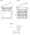
- the hanging position is a position where the handles (7) extend outwards the basket (3) and, by means of the handles (7), the basket (3) is hung between two planes with a certain gap therebetween, for instance upper sections of the body (2) ( Figure 1 , Figure 4, Figure 5 ).
- the handle (7) leans against the plane whereas the basket (3) extends below the plane level.
- the stacking position it is a position where the handles (7) are folded towards the interior of the basket (3) and where a second basket (30) is positioned onto the handles (7), if necessary ( Figure 2 , Figure 10, Figure 11 ).
- the handle (7) incorporates two housings (10) where two ends of the axis wire (4) are attached to and whereby, between the stacking and hanging positions, the handle (7) is moved by being rotated around the said wire (4), a bearing (11) that fits to the bearing wire (5) at stacking position, and a groove (12) fitting to the bearing wire (5) at hanging position.
- the handle (7) is basically an L-shape piece ( Figure 3 ). The inner corner of this L-shape faces downwards at hanging position and upwards at stacking position.
- the handle (7) comprises two plates (8, 9) forming the mentioned L-shape. On of these plates is carrying plate (8). At hanging position, this plate (8) extends approximately horizontal outwards from the side of the basket (3). At that position, by fitting the mentioned carrying plate (8) to the upper section of the body (2), food may be loaded into the basket (3). If necessary, the user may grasp the carrying plate (8) and pull out the basket (3) to transport the basket (3) from one place to another.
- the carrying plate (8) extends approximately horizontal towards the interior of the basket (3), the bottom of the upper basket (30) fitting onto the plate (8). If the user desires to pull out the basket (3) at stacking position, he/she can raise it by grasping the carrying plate (8). By means of the fixing plate (9) positioned vertically to the carrying plate (8), it is achieved that the handle (7) is attached to the basket (3) and can support the load applied.
- the handle (7) incorporates at least two slits (14) starting from one side of the fixing plate (9) extending up to the carrying plate (8). These slits (14) permit the handle (7) to be moved and rotated between the stacking and hanging positions such that the fixing plate (9) passes between the axis wire (4) and the bearing wire (5). Said slits (14) slide on the vertical supporting wires (6) as the handle (7) is being rotated. When the stacking position is attained, the supporting wires (6) lean against the carrying plate (8) through the slits (14). At stacking position, the supporting wires (6) pass through the slit (14) and extend upwards parallel to the fixing plate (9), above the carrying plate (8). Again at the stacking position, the portions of the fixing plate (9) at both sides of the slit (14) lean against the axis wire (4) from the outside.
- the handle also incorporates at least one projection (13) positioned above the carrying plate (8), extending in the same direction with and parallel to the fixing plate (9).
- This projection (13) squeezes the supporting wires (6) between the fixing plate (6) and itself as it leans against the mentioned supporting wires (6) that extend parallel to the fixing plate (9) ( Figure 11 ).
- said projection (13) permits the handle (7) to be detached from its position if and only if a force is applied at the lower side of the fixing plate (9) of the handle (7) along the supporting wires (6).
- the handle (7) When the user tries to pull out the basket (3) at stacking position, detaching the handle (7) from its position is not possible since the force applied at the carrying plate (8) is not along the supporting wires (6).
- the handle (7) By means of also the projection (13), the handle (7) is fixed at its position on the basket (3) and it is accomplished that it does not disengage with the wires (4, 5) and become free, in an unintended moment.
- the thickness of the mentioned projection (13) is adjusted such that, at stacking position, the upper basket (30) is not allowed to move in an inappropriate direction as it is fitted between the projections (13) at the opposite handles (7).
- the housing (10) is located at a position at two sides of the fixing plate (9) where the end of the axis wire (4) of the basket (3) fits into. There is a gap provided between two housings (10) so that the wire (4) of the basket (3) can be attached.
- the housing (10) is in form of a quadrangle the corners of which is rounded.
- the width of the housing (10) is approximately equal to the diameter of the wire (4). Whereas the length of said housing (10) is such that the wire (4) is able to lean against the interior of two ends of the housing (10) both at stacking and hanging positions.
- the longer side of the housing (10) is approximately parallel to the plane of fixing plate (9).
- the groove (12) is in form of a hook positioned at one side of the fixing plate (9) so as to grasp the bearing wire (5) from inside and below as the handle (7) is at hanging position.
- said groove (12) is positioned on top such that its opening faces the interior of the basket (3).
- the bearing (11) is positioned at the other side of the fixing plate (9) with respect to the groove (12) and at stacking position, grasps the bearing wire (5) from the top. As the handle (7) is at hanging position said bearing (11) is positioned on top such that its - opening faces upwards.
- the handle (7) incorporates channels (15) with proper shape and dimension, positioned at the surface of the carrying plate (8). This surface is supporting the upper basket (30) at stacking position, where the wires at the bottom of the mentioned basket (30) fit into ( Figure 11 ).
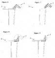
- the cooling device (1) subject to the present invention when the user is to load items, he/she brings the handle (7) to the hanging position and hangs the basket (3) to the upper sides of the body (2) ( Figure 1 ).
- the axis wire (4) is at upper most position inside the housing (10) wherein the groove (12) grasps the bearing wire (5) from inside and below ( Figure 4, Figure 5 ), whereas the bearing (11) is empty positioned on top.
- the supporting wires (6) are located near the end of the slit (14).
- the carrying plate (8) leans against the side of the body (2) from the upper side.
- the user brings the handle (7) from the hanging position to the stacking position.
- the handle (7) is rotated around the axis wire (14) such that the side of the fixing plate (9) moves towards the interior of the basket (3) ( Figure 6 ).
- the axis wire (4) is pulled upwards until it contacts the other end inside the housing (10) ( Figure 7 ).
- the lower side of the fixing plate (9) is located at the same level as the gap between two wires (4, 5).
- the handle (7) is rotated around the axis wire (4) for approximately 180o such that lower side of the fixing plate (9) comes out of the basket (3) through two wires (4, 5) ( Figure 8 ).
- the bearing (11) is located on top of the bearing wire (5), the supporting wires (6) reach a far most position inside the slit (14) and lean against the carrying plate (8) internally.
- the axis wire (4) is brought to an upper most position inside the housing (10), wherein the bearing (11) grasps the bearing wire (5) from the top ( Figure 9 ).
- the carrying plate (8) extends in horizontal plane, towards the interior of the basket (3) wherein the fixing plate (9) raises upwards from the side of the basket (3), being vertical to said carrying plate (8). Projections lean against the supporting wires (6) from the inside of the basket (3).
- the bottom wires of the upper basket (30) fit into the channels (15) positioned at the handle (7) of the lower basket (3) ( Figure 2 ). Furthermore, the lateral walls of the upper basket (30) are squeezed between the projections (13) of the handle (7) below. Thereby, the upper basket (30) is disabled to move in unintended directions, right-left, forwards-backwards.
- cooling device (1) By means of the cooling device (1) according to the present invention, both at hanging and stacking positions, it is accomplished to prevent the handle (7) from being detached from its position unless the user intends to do so.
Landscapes
- Engineering & Computer Science (AREA)
- Chemical & Material Sciences (AREA)
- Combustion & Propulsion (AREA)
- Physics & Mathematics (AREA)
- Mechanical Engineering (AREA)
- Thermal Sciences (AREA)
- General Engineering & Computer Science (AREA)
- Details Of Rigid Or Semi-Rigid Containers (AREA)
- Devices That Are Associated With Refrigeration Equipment (AREA)
Claims (6)
- Kühlvorrichtung (1), umfassend:- einen Gehäusekörper (2),- wenigstens einen Korb (3), in den Artikel gelegt werden und der gestapelt und in dem Gehäusekörper (2) angeordnet ist und auf zwei gegenüberliegenden Seiten einen Achsendraht (4), dessen beide Enden frei sind, einen horizontalen Lagerungsdraht (5) unter dem Achsendraht (4) und parallel dazu und wenigstens zwei vertikal aneinander ausgerichtete Stützdrähte (6) aufweist, die den Achsendraht (4) und den Lagerungsdraht (5) verbinden, und- zwei Griffe (7), die einander gegenüber an den Achsendrähten (4) und Lagerungsdrähten (5) des Korbs (3) angebracht sind, wodurch der Korb (3) in einer Hängeposition an seinen zwei Seiten aufgehängt und/oder transportiert werden kann und wodurch mehr als ein Korb (3, 30) in einer Stapelposition über dem anderen angeordnet werden kann, wobei der obere Korb von den Griffen (7) von unten abgestützt wird, wobei die Griffe (7) aus der Hängeposition in die Stapelposition bewegt werden können,und gekennzeichnet durch einen Griff (7), der Folgendes aufweist- eine Trägerplatte (8), die sich in der Hängeposition ungefähr horizontal von der Seite des Korbs (3) nach außen erstreckt, sich an die Oberseite des Gehäusekörpers (2) anlehnt und den Korb (3) stützt, während sie sich in der Stapelposition ungefähr horizontal nach innen zum Korb (3) erstreckt, wobei der Boden des oberen Korbs (30) darauf sitzt,- eine Befestigungsplatte (9), die vertikal an der Trägerplatte (8) angebracht ist, um eine L-Form zu bilden, und wodurch der Griff (7) am Korb (3) angebracht ist und die ausgeübte Belastung abstützt,- zwei Gehäuse (10) an der Befestigungsplatte (9), an denen zwei Enden des Achsendrahts (4) angebracht sind und wodurch der Griff (7) zwischen der Stapel- und der Hängeposition durch Drehen um den Draht (4) bewegt wird,- ein Lager (11), das an einer Seite der Befestigungsplatte (9) angeordnet ist, wobei das Lager (11) in der Stapelposition mit dem Lagerdraht (5) zusammenpasst,- eine Nut (12), die an der anderen Seite der Befestigungsplatte (9) angeordnet ist und in der Hängeposition mit dem Lagerdraht (5) zusammenpasst,- wenigstens zwei Schlitze (14), die von einer Seite der Befestigungsplatte (9) ausgehen und sich bis hinauf zur Trägerplatte (8) erstreckten, wobei deren Schlitze (14) es dem Griff (7) erlauben, bewegt und zwischen der Stapel- und der Hängeposition bewegt zu werden, derart, dass die Befestigungsplatte (9) zwischen dem Achsendraht (4) und dem Lagerungsdraht (5) hindurch tritt, wobei die Schlitze (14) an den vertikalen Stützdrähten (6) gleiten, wenn der Griff (7) gedreht wird, wobei sich die Stützdrähte (6) an der Trägerplatte (8) anlehnen, indem sie durch sie hindurch verlaufen.
- Kühlvorrichtung (1) nach Anspruch 1, gekennzeichnet durch einen Griff (7), der wenigstens einen Vorsprung (13) aufweist, der über der Trägerplatte (8) angeordnet ist und sich in dieselbe Richtung wie die Befestigungsplatte (9) und parallel dazu erstreckt, wobei deren Vorsprung (13) in der Stapelposition die Stützdrähte (6) zwischen sich und der Befestigungsplatte (6) zusammendrückt und sich an die Stützdrähte (6) anlegt, die sich parallel zur Befestigungsplatte (9) erstrecken.
- Kühlvorrichtung (1) nach den Ansprüchen 1 oder 2, gekennzeichnet durch einen Griff (7), der zwei gegenüberliegende Gehäuse (10) aufweist, die an zwei Seiten der Befestigungsplatte (9) angeordnet sind, in die die Enden des Achsendrahts (4) eingesetzt sind, wobei ein Spalt dazwischen vorgesehen ist, derart, dass der Achsendraht (4) angebracht werden kann, und dessen Gehäuse (10) die Form eines Vierecks aufweisen, dessen Ecken abgerundet sind, derart, dass der Achsendraht (4) sich gleitend daran bewegen kann, während der Griff (7) zwischen der Hänge- und der Stapelposition bewegt wird.
- Kühlvorrichtung (1) nach den Ansprüchen 1, 2 oder 3, gekennzeichnet durch einen Griff (7), der eine Nut (12) in der Form eines Hakens aufweist, die an einer Seite der Befestigungsplatte (9) angeordnet ist, um den Lagerdraht (5) von innen und unten zu ergreifen, wenn der Griff (7) in der Hängeposition ist.
- Kühlvorrichtung (1) nach einem der vorangehenden Ansprüche, gekennzeichnet durch einen Griff (7), der Lager (11) aufweist, das an der anderen Seite der Befestigungsplatte (9) angeordnet ist und in der Stapelposition den Lagerungsdraht (5) von oben ergreift.
- Kühlvorrichtung (1) nach einem der vorangehenden Ansprüche, gekennzeichnet durch einen Griff (7), der Kanäle (15) mit einer geeigneten Form und Abmessung aufweist, die an der Oberfläche der Trägerplatte (8) angeordnet sind, deren Oberfläche den oberen Korb (30) in der Stapelposition abstützt und in die die Drähte am Boden des Korb (30) passen.
Applications Claiming Priority (2)
| Application Number | Priority Date | Filing Date | Title |
|---|---|---|---|
| TR200503547 | 2005-09-05 | ||
| PCT/IB2006/053122 WO2007029182A2 (en) | 2005-09-05 | 2006-09-05 | A cooling device |
Publications (2)
| Publication Number | Publication Date |
|---|---|
| EP1922518A2 EP1922518A2 (de) | 2008-05-21 |
| EP1922518B1 true EP1922518B1 (de) | 2016-04-06 |
Family
ID=37836223
Family Applications (1)
| Application Number | Title | Priority Date | Filing Date |
|---|---|---|---|
| EP06795918.9A Active EP1922518B1 (de) | 2005-09-05 | 2006-09-05 | Kühlvorrichtung |
Country Status (3)
| Country | Link |
|---|---|
| EP (1) | EP1922518B1 (de) |
| PL (1) | PL1922518T3 (de) |
| WO (1) | WO2007029182A2 (de) |
Families Citing this family (4)
| Publication number | Priority date | Publication date | Assignee | Title |
|---|---|---|---|---|
| ITVA20130033A1 (it) * | 2013-06-11 | 2014-12-12 | Whirlpool Co | Sistema di contenimento di prodotti alimentari in congelatori orizzontali e congelatore orizzontale provvisto di tale sistema |
| DE102016008065A1 (de) * | 2016-06-30 | 2018-01-04 | Liebherr-Hausgeräte Lienz Gmbh | Behälter für eine Kühl- oder Gefriertruhe |
| CN108870853B (zh) * | 2018-06-19 | 2020-11-03 | 海信容声(广东)冷柜有限公司 | 篮筐安装结构和冷柜 |
| CN113465279B (zh) * | 2021-07-30 | 2024-08-27 | 浙江星星冷链集成股份有限公司 | 一种承重效果好的冰淇淋柜网篮 |
Family Cites Families (3)
| Publication number | Priority date | Publication date | Assignee | Title |
|---|---|---|---|---|
| IT1077303B (it) * | 1977-06-03 | 1985-05-04 | Locatelli Gianbattista | Struttra di maniglia per contenitori in genere e per cestelli per congelatori e simili in particolare |
| DE2832929C3 (de) * | 1978-07-27 | 1981-03-26 | Drahtwarenfabrik Drahtzug Stein KG, 57645 Nister | Drahtkorb |
| JPH092482A (ja) * | 1995-06-23 | 1997-01-07 | Midori Anzen Co Ltd | バスケットとその取手 |
-
2006
- 2006-09-05 EP EP06795918.9A patent/EP1922518B1/de active Active
- 2006-09-05 WO PCT/IB2006/053122 patent/WO2007029182A2/en not_active Ceased
- 2006-09-05 PL PL06795918.9T patent/PL1922518T3/pl unknown
Also Published As
| Publication number | Publication date |
|---|---|
| WO2007029182A3 (en) | 2007-10-18 |
| WO2007029182A2 (en) | 2007-03-15 |
| EP1922518A2 (de) | 2008-05-21 |
| PL1922518T3 (pl) | 2016-10-31 |
Similar Documents
| Publication | Publication Date | Title |
|---|---|---|
| US6926001B2 (en) | Oven rack | |
| EP2314965B1 (de) | Kühlschrank mit unterteilten Regalböden | |
| US3834865A (en) | Dolly structure | |
| EP1922518B1 (de) | Kühlvorrichtung | |
| US9227643B1 (en) | Wheeled transport for slow cooker | |
| KR20080059758A (ko) | 냉장고 | |
| US10722072B2 (en) | Sous vide rack | |
| GB2523111A (en) | A box capable of being assembled and disassembled | |
| US10646075B2 (en) | Aluminum foil pan carrier system | |
| KR102920017B1 (ko) | 냉장고 | |
| AU2021327811B2 (en) | Adjustable shelf device and refrigerator having same | |
| KR101832620B1 (ko) | 접철식 캠핑용 그릴 | |
| WO2007110440A2 (en) | A cooling device | |
| KR101237697B1 (ko) | 냉장고 | |
| KR100925313B1 (ko) | 주방용기용 절첩 연장식 손잡이 | |
| KR101174538B1 (ko) | 냉장고 | |
| CN210384646U (zh) | 移动式应急器材柜 | |
| KR101289708B1 (ko) | 용기 수납용 선반 어셈블리 및 그를 구비한 냉장고 | |
| JP5671690B2 (ja) | 電気調理器用収納ケース | |
| WO2017072665A1 (en) | Apparatus of containment and transport of objects | |
| US20230010125A1 (en) | Table-top cooler | |
| KR20160008388A (ko) | 온도제어가 가능한 이동식 저장창고 | |
| JP2003050083A (ja) | 冷蔵庫の棚装置 | |
| KR20120070370A (ko) | 코일 거치장치 | |
| KR101178343B1 (ko) | 냉장고 |
Legal Events
| Date | Code | Title | Description |
|---|---|---|---|
| PUAI | Public reference made under article 153(3) epc to a published international application that has entered the european phase |
Free format text: ORIGINAL CODE: 0009012 |
|
| 17P | Request for examination filed |
Effective date: 20080307 |
|
| AK | Designated contracting states |
Kind code of ref document: A2 Designated state(s): AT BE BG CH CY CZ DE DK EE ES FI FR GB GR HU IE IS IT LI LT LU LV MC NL PL PT RO SE SI SK TR |
|
| AX | Request for extension of the european patent |
Extension state: AL BA HR MK RS |
|
| DAX | Request for extension of the european patent (deleted) | ||
| 17Q | First examination report despatched |
Effective date: 20140307 |
|
| GRAP | Despatch of communication of intention to grant a patent |
Free format text: ORIGINAL CODE: EPIDOSNIGR1 |
|
| INTG | Intention to grant announced |
Effective date: 20151127 |
|
| GRAS | Grant fee paid |
Free format text: ORIGINAL CODE: EPIDOSNIGR3 |
|
| GRAA | (expected) grant |
Free format text: ORIGINAL CODE: 0009210 |
|
| AK | Designated contracting states |
Kind code of ref document: B1 Designated state(s): AT BE BG CH CY CZ DE DK EE ES FI FR GB GR HU IE IS IT LI LT LU LV MC NL PL PT RO SE SI SK TR |
|
| REG | Reference to a national code |
Ref country code: GB Ref legal event code: FG4D |
|
| REG | Reference to a national code |
Ref country code: AT Ref legal event code: REF Ref document number: 788273 Country of ref document: AT Kind code of ref document: T Effective date: 20160415 Ref country code: CH Ref legal event code: EP |
|
| REG | Reference to a national code |
Ref country code: IE Ref legal event code: FG4D |
|
| REG | Reference to a national code |
Ref country code: DE Ref legal event code: R096 Ref document number: 602006048561 Country of ref document: DE |
|
| REG | Reference to a national code |
Ref country code: RO Ref legal event code: EPE |
|
| REG | Reference to a national code |
Ref country code: LT Ref legal event code: MG4D Ref country code: NL Ref legal event code: MP Effective date: 20160406 |
|
| REG | Reference to a national code |
Ref country code: AT Ref legal event code: MK05 Ref document number: 788273 Country of ref document: AT Kind code of ref document: T Effective date: 20160406 |
|
| REG | Reference to a national code |
Ref country code: FR Ref legal event code: PLFP Year of fee payment: 11 |
|
| PG25 | Lapsed in a contracting state [announced via postgrant information from national office to epo] |
Ref country code: NL Free format text: LAPSE BECAUSE OF FAILURE TO SUBMIT A TRANSLATION OF THE DESCRIPTION OR TO PAY THE FEE WITHIN THE PRESCRIBED TIME-LIMIT Effective date: 20160406 |
|
| PG25 | Lapsed in a contracting state [announced via postgrant information from national office to epo] |
Ref country code: FI Free format text: LAPSE BECAUSE OF FAILURE TO SUBMIT A TRANSLATION OF THE DESCRIPTION OR TO PAY THE FEE WITHIN THE PRESCRIBED TIME-LIMIT Effective date: 20160406 Ref country code: IS Free format text: LAPSE BECAUSE OF FAILURE TO SUBMIT A TRANSLATION OF THE DESCRIPTION OR TO PAY THE FEE WITHIN THE PRESCRIBED TIME-LIMIT Effective date: 20160806 Ref country code: LT Free format text: LAPSE BECAUSE OF FAILURE TO SUBMIT A TRANSLATION OF THE DESCRIPTION OR TO PAY THE FEE WITHIN THE PRESCRIBED TIME-LIMIT Effective date: 20160406 |
|
| PG25 | Lapsed in a contracting state [announced via postgrant information from national office to epo] |
Ref country code: LV Free format text: LAPSE BECAUSE OF FAILURE TO SUBMIT A TRANSLATION OF THE DESCRIPTION OR TO PAY THE FEE WITHIN THE PRESCRIBED TIME-LIMIT Effective date: 20160406 Ref country code: PT Free format text: LAPSE BECAUSE OF FAILURE TO SUBMIT A TRANSLATION OF THE DESCRIPTION OR TO PAY THE FEE WITHIN THE PRESCRIBED TIME-LIMIT Effective date: 20160808 Ref country code: GR Free format text: LAPSE BECAUSE OF FAILURE TO SUBMIT A TRANSLATION OF THE DESCRIPTION OR TO PAY THE FEE WITHIN THE PRESCRIBED TIME-LIMIT Effective date: 20160707 Ref country code: ES Free format text: LAPSE BECAUSE OF FAILURE TO SUBMIT A TRANSLATION OF THE DESCRIPTION OR TO PAY THE FEE WITHIN THE PRESCRIBED TIME-LIMIT Effective date: 20160406 Ref country code: AT Free format text: LAPSE BECAUSE OF FAILURE TO SUBMIT A TRANSLATION OF THE DESCRIPTION OR TO PAY THE FEE WITHIN THE PRESCRIBED TIME-LIMIT Effective date: 20160406 Ref country code: SE Free format text: LAPSE BECAUSE OF FAILURE TO SUBMIT A TRANSLATION OF THE DESCRIPTION OR TO PAY THE FEE WITHIN THE PRESCRIBED TIME-LIMIT Effective date: 20160406 |
|
| PG25 | Lapsed in a contracting state [announced via postgrant information from national office to epo] |
Ref country code: BE Free format text: LAPSE BECAUSE OF FAILURE TO SUBMIT A TRANSLATION OF THE DESCRIPTION OR TO PAY THE FEE WITHIN THE PRESCRIBED TIME-LIMIT Effective date: 20160406 |
|
| REG | Reference to a national code |
Ref country code: DE Ref legal event code: R097 Ref document number: 602006048561 Country of ref document: DE |
|
| PG25 | Lapsed in a contracting state [announced via postgrant information from national office to epo] |
Ref country code: DK Free format text: LAPSE BECAUSE OF FAILURE TO SUBMIT A TRANSLATION OF THE DESCRIPTION OR TO PAY THE FEE WITHIN THE PRESCRIBED TIME-LIMIT Effective date: 20160406 Ref country code: EE Free format text: LAPSE BECAUSE OF FAILURE TO SUBMIT A TRANSLATION OF THE DESCRIPTION OR TO PAY THE FEE WITHIN THE PRESCRIBED TIME-LIMIT Effective date: 20160406 Ref country code: SK Free format text: LAPSE BECAUSE OF FAILURE TO SUBMIT A TRANSLATION OF THE DESCRIPTION OR TO PAY THE FEE WITHIN THE PRESCRIBED TIME-LIMIT Effective date: 20160406 Ref country code: CZ Free format text: LAPSE BECAUSE OF FAILURE TO SUBMIT A TRANSLATION OF THE DESCRIPTION OR TO PAY THE FEE WITHIN THE PRESCRIBED TIME-LIMIT Effective date: 20160406 |
|
| PLBE | No opposition filed within time limit |
Free format text: ORIGINAL CODE: 0009261 |
|
| STAA | Information on the status of an ep patent application or granted ep patent |
Free format text: STATUS: NO OPPOSITION FILED WITHIN TIME LIMIT |
|
| 26N | No opposition filed |
Effective date: 20170110 |
|
| PG25 | Lapsed in a contracting state [announced via postgrant information from national office to epo] |
Ref country code: MC Free format text: LAPSE BECAUSE OF FAILURE TO SUBMIT A TRANSLATION OF THE DESCRIPTION OR TO PAY THE FEE WITHIN THE PRESCRIBED TIME-LIMIT Effective date: 20160406 |
|
| REG | Reference to a national code |
Ref country code: CH Ref legal event code: PL |
|
| PG25 | Lapsed in a contracting state [announced via postgrant information from national office to epo] |
Ref country code: SI Free format text: LAPSE BECAUSE OF FAILURE TO SUBMIT A TRANSLATION OF THE DESCRIPTION OR TO PAY THE FEE WITHIN THE PRESCRIBED TIME-LIMIT Effective date: 20160406 |
|
| REG | Reference to a national code |
Ref country code: IE Ref legal event code: MM4A |
|
| PG25 | Lapsed in a contracting state [announced via postgrant information from national office to epo] |
Ref country code: CH Free format text: LAPSE BECAUSE OF NON-PAYMENT OF DUE FEES Effective date: 20160930 Ref country code: IE Free format text: LAPSE BECAUSE OF NON-PAYMENT OF DUE FEES Effective date: 20160905 Ref country code: LI Free format text: LAPSE BECAUSE OF NON-PAYMENT OF DUE FEES Effective date: 20160930 |
|
| PG25 | Lapsed in a contracting state [announced via postgrant information from national office to epo] |
Ref country code: LU Free format text: LAPSE BECAUSE OF NON-PAYMENT OF DUE FEES Effective date: 20160905 |
|
| REG | Reference to a national code |
Ref country code: FR Ref legal event code: PLFP Year of fee payment: 12 |
|
| PGFP | Annual fee paid to national office [announced via postgrant information from national office to epo] |
Ref country code: MC Payment date: 20170621 Year of fee payment: 8 |
|
| PG25 | Lapsed in a contracting state [announced via postgrant information from national office to epo] |
Ref country code: HU Free format text: LAPSE BECAUSE OF FAILURE TO SUBMIT A TRANSLATION OF THE DESCRIPTION OR TO PAY THE FEE WITHIN THE PRESCRIBED TIME-LIMIT; INVALID AB INITIO Effective date: 20060905 Ref country code: CY Free format text: LAPSE BECAUSE OF FAILURE TO SUBMIT A TRANSLATION OF THE DESCRIPTION OR TO PAY THE FEE WITHIN THE PRESCRIBED TIME-LIMIT Effective date: 20160406 |
|
| PG25 | Lapsed in a contracting state [announced via postgrant information from national office to epo] |
Ref country code: BG Free format text: LAPSE BECAUSE OF FAILURE TO SUBMIT A TRANSLATION OF THE DESCRIPTION OR TO PAY THE FEE WITHIN THE PRESCRIBED TIME-LIMIT Effective date: 20160406 |
|
| PG25 | Lapsed in a contracting state [announced via postgrant information from national office to epo] |
Ref country code: FR Free format text: LAPSE BECAUSE OF NON-PAYMENT OF DUE FEES Effective date: 20180930 |
|
| PGFP | Annual fee paid to national office [announced via postgrant information from national office to epo] |
Ref country code: IT Payment date: 20190925 Year of fee payment: 14 Ref country code: RO Payment date: 20190830 Year of fee payment: 14 |
|
| PG25 | Lapsed in a contracting state [announced via postgrant information from national office to epo] |
Ref country code: RO Free format text: LAPSE BECAUSE OF NON-PAYMENT OF DUE FEES Effective date: 20200905 |
|
| PG25 | Lapsed in a contracting state [announced via postgrant information from national office to epo] |
Ref country code: IT Free format text: LAPSE BECAUSE OF NON-PAYMENT OF DUE FEES Effective date: 20200905 |
|
| PGFP | Annual fee paid to national office [announced via postgrant information from national office to epo] |
Ref country code: PL Payment date: 20210826 Year of fee payment: 16 Ref country code: GB Payment date: 20210920 Year of fee payment: 16 |
|
| GBPC | Gb: european patent ceased through non-payment of renewal fee |
Effective date: 20220905 |
|
| PG25 | Lapsed in a contracting state [announced via postgrant information from national office to epo] |
Ref country code: GB Free format text: LAPSE BECAUSE OF NON-PAYMENT OF DUE FEES Effective date: 20220905 |
|
| PG25 | Lapsed in a contracting state [announced via postgrant information from national office to epo] |
Ref country code: PL Free format text: LAPSE BECAUSE OF NON-PAYMENT OF DUE FEES Effective date: 20220905 |
|
| PGFP | Annual fee paid to national office [announced via postgrant information from national office to epo] |
Ref country code: TR Payment date: 20240826 Year of fee payment: 19 |
|
| PGFP | Annual fee paid to national office [announced via postgrant information from national office to epo] |
Ref country code: DE Payment date: 20250919 Year of fee payment: 20 |