EP1921241A1 - Door opening/closing device for vehicle - Google Patents
Door opening/closing device for vehicle Download PDFInfo
- Publication number
- EP1921241A1 EP1921241A1 EP06796316A EP06796316A EP1921241A1 EP 1921241 A1 EP1921241 A1 EP 1921241A1 EP 06796316 A EP06796316 A EP 06796316A EP 06796316 A EP06796316 A EP 06796316A EP 1921241 A1 EP1921241 A1 EP 1921241A1
- Authority
- EP
- European Patent Office
- Prior art keywords
- door
- opening
- housing
- rotor
- vehicle
- Prior art date
- Legal status (The legal status is an assumption and is not a legal conclusion. Google has not performed a legal analysis and makes no representation as to the accuracy of the status listed.)
- Granted
Links
Images







Classifications
-
- B—PERFORMING OPERATIONS; TRANSPORTING
- B60—VEHICLES IN GENERAL
- B60J—WINDOWS, WINDSCREENS, NON-FIXED ROOFS, DOORS, OR SIMILAR DEVICES FOR VEHICLES; REMOVABLE EXTERNAL PROTECTIVE COVERINGS SPECIALLY ADAPTED FOR VEHICLES
- B60J5/00—Doors
- B60J5/10—Doors arranged at the vehicle rear
- B60J5/101—Doors arranged at the vehicle rear for non-load transporting vehicles, i.e. family cars including vans
- B60J5/102—Doors arranged at the vehicle rear for non-load transporting vehicles, i.e. family cars including vans comprising door or part of door being pivotable downwards about horizontal axis to open position
- B60J5/103—Doors arranged at the vehicle rear for non-load transporting vehicles, i.e. family cars including vans comprising door or part of door being pivotable downwards about horizontal axis to open position where lower door part moves independently from other door structures, e.g. by being hinged on the vehicle body
-
- E—FIXED CONSTRUCTIONS
- E05—LOCKS; KEYS; WINDOW OR DOOR FITTINGS; SAFES
- E05D—HINGES OR SUSPENSION DEVICES FOR DOORS, WINDOWS OR WINGS
- E05D11/00—Additional features or accessories of hinges
- E05D11/08—Friction devices between relatively-movable hinge parts
- E05D11/082—Friction devices between relatively-movable hinge parts with substantially radial friction, e.g. cylindrical friction surfaces
- E05D11/084—Friction devices between relatively-movable hinge parts with substantially radial friction, e.g. cylindrical friction surfaces the friction depending on direction of rotation or opening angle of the hinge
-
- E—FIXED CONSTRUCTIONS
- E05—LOCKS; KEYS; WINDOW OR DOOR FITTINGS; SAFES
- E05F—DEVICES FOR MOVING WINGS INTO OPEN OR CLOSED POSITION; CHECKS FOR WINGS; WING FITTINGS NOT OTHERWISE PROVIDED FOR, CONCERNED WITH THE FUNCTIONING OF THE WING
- E05F3/00—Closers or openers with braking devices, e.g. checks; Construction of pneumatic or liquid braking devices
- E05F3/14—Closers or openers with braking devices, e.g. checks; Construction of pneumatic or liquid braking devices with fluid brakes of the rotary type
-
- E—FIXED CONSTRUCTIONS
- E05—LOCKS; KEYS; WINDOW OR DOOR FITTINGS; SAFES
- E05F—DEVICES FOR MOVING WINGS INTO OPEN OR CLOSED POSITION; CHECKS FOR WINGS; WING FITTINGS NOT OTHERWISE PROVIDED FOR, CONCERNED WITH THE FUNCTIONING OF THE WING
- E05F3/00—Closers or openers with braking devices, e.g. checks; Construction of pneumatic or liquid braking devices
- E05F3/20—Closers or openers with braking devices, e.g. checks; Construction of pneumatic or liquid braking devices in hinges
-
- E—FIXED CONSTRUCTIONS
- E05—LOCKS; KEYS; WINDOW OR DOOR FITTINGS; SAFES
- E05F—DEVICES FOR MOVING WINGS INTO OPEN OR CLOSED POSITION; CHECKS FOR WINGS; WING FITTINGS NOT OTHERWISE PROVIDED FOR, CONCERNED WITH THE FUNCTIONING OF THE WING
- E05F5/00—Braking devices, e.g. checks; Stops; Buffers
-
- E—FIXED CONSTRUCTIONS
- E05—LOCKS; KEYS; WINDOW OR DOOR FITTINGS; SAFES
- E05Y—INDEXING SCHEME ASSOCIATED WITH SUBCLASSES E05D AND E05F, RELATING TO CONSTRUCTION ELEMENTS, ELECTRIC CONTROL, POWER SUPPLY, POWER SIGNAL OR TRANSMISSION, USER INTERFACES, MOUNTING OR COUPLING, DETAILS, ACCESSORIES, AUXILIARY OPERATIONS NOT OTHERWISE PROVIDED FOR, APPLICATION THEREOF
- E05Y2201/00—Constructional elements; Accessories therefor
- E05Y2201/20—Brakes; Disengaging means; Holders; Stops; Valves; Accessories therefor
- E05Y2201/21—Brakes
-
- E—FIXED CONSTRUCTIONS
- E05—LOCKS; KEYS; WINDOW OR DOOR FITTINGS; SAFES
- E05Y—INDEXING SCHEME ASSOCIATED WITH SUBCLASSES E05D AND E05F, RELATING TO CONSTRUCTION ELEMENTS, ELECTRIC CONTROL, POWER SUPPLY, POWER SIGNAL OR TRANSMISSION, USER INTERFACES, MOUNTING OR COUPLING, DETAILS, ACCESSORIES, AUXILIARY OPERATIONS NOT OTHERWISE PROVIDED FOR, APPLICATION THEREOF
- E05Y2201/00—Constructional elements; Accessories therefor
- E05Y2201/20—Brakes; Disengaging means; Holders; Stops; Valves; Accessories therefor
- E05Y2201/25—Mechanical means for force or torque adjustment therefor
-
- E—FIXED CONSTRUCTIONS
- E05—LOCKS; KEYS; WINDOW OR DOOR FITTINGS; SAFES
- E05Y—INDEXING SCHEME ASSOCIATED WITH SUBCLASSES E05D AND E05F, RELATING TO CONSTRUCTION ELEMENTS, ELECTRIC CONTROL, POWER SUPPLY, POWER SIGNAL OR TRANSMISSION, USER INTERFACES, MOUNTING OR COUPLING, DETAILS, ACCESSORIES, AUXILIARY OPERATIONS NOT OTHERWISE PROVIDED FOR, APPLICATION THEREOF
- E05Y2201/00—Constructional elements; Accessories therefor
- E05Y2201/20—Brakes; Disengaging means; Holders; Stops; Valves; Accessories therefor
- E05Y2201/252—Type of friction
- E05Y2201/254—Fluid or viscous friction
- E05Y2201/256—Fluid or viscous friction with pistons or vanes
-
- E—FIXED CONSTRUCTIONS
- E05—LOCKS; KEYS; WINDOW OR DOOR FITTINGS; SAFES
- E05Y—INDEXING SCHEME ASSOCIATED WITH SUBCLASSES E05D AND E05F, RELATING TO CONSTRUCTION ELEMENTS, ELECTRIC CONTROL, POWER SUPPLY, POWER SIGNAL OR TRANSMISSION, USER INTERFACES, MOUNTING OR COUPLING, DETAILS, ACCESSORIES, AUXILIARY OPERATIONS NOT OTHERWISE PROVIDED FOR, APPLICATION THEREOF
- E05Y2201/00—Constructional elements; Accessories therefor
- E05Y2201/20—Brakes; Disengaging means; Holders; Stops; Valves; Accessories therefor
- E05Y2201/262—Type of motion, e.g. braking
- E05Y2201/266—Type of motion, e.g. braking rotary
-
- E—FIXED CONSTRUCTIONS
- E05—LOCKS; KEYS; WINDOW OR DOOR FITTINGS; SAFES
- E05Y—INDEXING SCHEME ASSOCIATED WITH SUBCLASSES E05D AND E05F, RELATING TO CONSTRUCTION ELEMENTS, ELECTRIC CONTROL, POWER SUPPLY, POWER SIGNAL OR TRANSMISSION, USER INTERFACES, MOUNTING OR COUPLING, DETAILS, ACCESSORIES, AUXILIARY OPERATIONS NOT OTHERWISE PROVIDED FOR, APPLICATION THEREOF
- E05Y2201/00—Constructional elements; Accessories therefor
- E05Y2201/40—Motors; Magnets; Springs; Weights; Accessories therefor
- E05Y2201/404—Function thereof
- E05Y2201/422—Function thereof for opening
- E05Y2201/424—Function thereof for opening for the final opening movement
-
- E—FIXED CONSTRUCTIONS
- E05—LOCKS; KEYS; WINDOW OR DOOR FITTINGS; SAFES
- E05Y—INDEXING SCHEME ASSOCIATED WITH SUBCLASSES E05D AND E05F, RELATING TO CONSTRUCTION ELEMENTS, ELECTRIC CONTROL, POWER SUPPLY, POWER SIGNAL OR TRANSMISSION, USER INTERFACES, MOUNTING OR COUPLING, DETAILS, ACCESSORIES, AUXILIARY OPERATIONS NOT OTHERWISE PROVIDED FOR, APPLICATION THEREOF
- E05Y2800/00—Details, accessories and auxiliary operations not otherwise provided for
- E05Y2800/20—Combinations of elements
- E05Y2800/205—Combinations of elements forming a unit
-
- E—FIXED CONSTRUCTIONS
- E05—LOCKS; KEYS; WINDOW OR DOOR FITTINGS; SAFES
- E05Y—INDEXING SCHEME ASSOCIATED WITH SUBCLASSES E05D AND E05F, RELATING TO CONSTRUCTION ELEMENTS, ELECTRIC CONTROL, POWER SUPPLY, POWER SIGNAL OR TRANSMISSION, USER INTERFACES, MOUNTING OR COUPLING, DETAILS, ACCESSORIES, AUXILIARY OPERATIONS NOT OTHERWISE PROVIDED FOR, APPLICATION THEREOF
- E05Y2900/00—Application of doors, windows, wings or fittings thereof
- E05Y2900/50—Application of doors, windows, wings or fittings thereof for vehicles
- E05Y2900/516—Application of doors, windows, wings or fittings thereof for vehicles for trucks or trailers
-
- E—FIXED CONSTRUCTIONS
- E05—LOCKS; KEYS; WINDOW OR DOOR FITTINGS; SAFES
- E05Y—INDEXING SCHEME ASSOCIATED WITH SUBCLASSES E05D AND E05F, RELATING TO CONSTRUCTION ELEMENTS, ELECTRIC CONTROL, POWER SUPPLY, POWER SIGNAL OR TRANSMISSION, USER INTERFACES, MOUNTING OR COUPLING, DETAILS, ACCESSORIES, AUXILIARY OPERATIONS NOT OTHERWISE PROVIDED FOR, APPLICATION THEREOF
- E05Y2900/00—Application of doors, windows, wings or fittings thereof
- E05Y2900/50—Application of doors, windows, wings or fittings thereof for vehicles
- E05Y2900/53—Type of wing
- E05Y2900/531—Doors
-
- E—FIXED CONSTRUCTIONS
- E05—LOCKS; KEYS; WINDOW OR DOOR FITTINGS; SAFES
- E05Y—INDEXING SCHEME ASSOCIATED WITH SUBCLASSES E05D AND E05F, RELATING TO CONSTRUCTION ELEMENTS, ELECTRIC CONTROL, POWER SUPPLY, POWER SIGNAL OR TRANSMISSION, USER INTERFACES, MOUNTING OR COUPLING, DETAILS, ACCESSORIES, AUXILIARY OPERATIONS NOT OTHERWISE PROVIDED FOR, APPLICATION THEREOF
- E05Y2900/00—Application of doors, windows, wings or fittings thereof
- E05Y2900/50—Application of doors, windows, wings or fittings thereof for vehicles
- E05Y2900/53—Type of wing
- E05Y2900/544—Tailboards, tailgates or sideboards opening downwards
-
- E—FIXED CONSTRUCTIONS
- E05—LOCKS; KEYS; WINDOW OR DOOR FITTINGS; SAFES
- E05Y—INDEXING SCHEME ASSOCIATED WITH SUBCLASSES E05D AND E05F, RELATING TO CONSTRUCTION ELEMENTS, ELECTRIC CONTROL, POWER SUPPLY, POWER SIGNAL OR TRANSMISSION, USER INTERFACES, MOUNTING OR COUPLING, DETAILS, ACCESSORIES, AUXILIARY OPERATIONS NOT OTHERWISE PROVIDED FOR, APPLICATION THEREOF
- E05Y2900/00—Application of doors, windows, wings or fittings thereof
- E05Y2900/50—Application of doors, windows, wings or fittings thereof for vehicles
- E05Y2900/53—Type of wing
- E05Y2900/546—Tailboards, tailgates or sideboards opening upwards
Definitions
- the present invention relates to a door opening/closing device for vehicle and, particularly, to a door opening/closing device provided with a damper for imparting a braking force to a door when the door is turned with respect to a vehicle body.
- a back door 940 for opening/closing an opening of a vehicle body includes an upper door 945 for opening/closing the upper part of the opening and a lower door 951 for opening/closing the lower part of the opening.
- the upper door 945 is pivotally connected, at its upper end, to a rear end of a vehicle roof by an upper hinge so as to be turned upward and downward.
- the upper door 945 is flipped up to open the opening.
- the lower door 951 is pivotally connected, at its lower end, to a rear end of a vehicle floor by a lower hinge so as to be turned upward and downward.
- the lower door 951 is turned to a horizontal position to open the opening.
- each damper 9427 is in the shape of a telescopic rod including a cylinder and a piston rod, the ends of which are connected to a side edge of the opening and a side end of the lower door 941 respectively.
- Patent Document 1 JP 1-14112(1989)U
- each damper 9427 is stretched between the side end of the lower door 941 and the side edge of the opening, resulting in interference with the work of taking in and out baggage and deterioration of the appearance.
- the present invention has been made to solve the above problems and has a purpose to provide a door opening/closing device for vehicle, including a damper that does not interfere with the work of taking in and out baggage and can provide a good appearance.
- a vehicle door opening/closing device set forth in claim 1 is characterized in a vehicle door opening/closing device including a hinge member for pivotally connecting a door for opening and closing an opening of a vehicle body to the vehicle body, and a damper for imparting a braking force to the door when the door is turned relative to the vehicle body, wherein the hinge member includes: a first hinge arm to be attached to one of an edge of the opening and an end of the door facing to each other; a pin shaft fixed to the first hinge arm to be placed along the edge of the opening and the end of the door; and a second hinge arm pivotally mounted on the pin shaft and to be attached to the other one of the edge of the opening and the end of the door, and the damper includes: a rotor connected to the pin shaft; a housing rotatably mounted on the rotor and to be attached to the other one of the vehicle body and the door, or, the second hinge arm; a braking means contained in the housing and arranged to impart a braking force to the
- the damper is placed on the axis line of the pin shaft of the hinge member between the edge portion of the opening and the end portion of the door.
- the damper will not interfere with the work of taking in and out baggage and can provide a good appearance.
- the door opening/closing device for vehicle set forth in claim 2 of the invention is characterized in that, in the door opening/closing device for vehicle of claim 1, one end of the pin shaft forms a projecting portion that extends outward of both hinge arms and is connected to the rotor. Accordingly, a simple structure for connecting the damper to the hinge member can be achieved.
- the door opening/closing device for vehicle set forth in claim 3 of the invention is characterized in that, in the door opening/closing device for vehicle of claim 1 or 2, the hinge member is arranged to connect a lower end of the door to the vehicle body in such a way that the door can be turned upward and downward, and the damper is arranged to increase the braking force as the door is turned in an opening direction. Accordingly, the braking force is small in the vicinity of the closed position and therefore the door can be opened smoothly. Since the braking force is increased toward the open position, the door can be prevented from being burst open and rattling by its own weight.
- the damper will not interfere with the work of taking in and out baggage and can provide a good appearance.
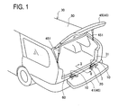
- Fig. 1 is a perspective rear view of a vehicle, showing an open state of a back door
- Fig. 2 is a sectional view taken along a line II-II in Fig. 1
- Fig. 3 is a sectional view of the same with a lower door closed.
- a rear opening 31 of a vehicle body 30 can be opened and closed by a back door 40.
- the back door 40 includes an upper door 45 for opening and closing the upper part of the rear opening 31 and a lower door 41 for opening and closing the lower part of the rear opening 31.
- the upper door 45 and the lower door 41 are pivotally connected to the vehicle body 30 respectively so as to be opened and closed by a predetermined operation with opening/closing devices.
- a vehicle door opening/closing device 1 according to the present invention is applied to an opening/closing device for the lower door 41.
- An opening/closing device for the upper door 45 is comprised of a hinge member (not shown) for pivotally supporting the upper door 45 so that the upper door 45 can be turn upward and downward relative to the vehicle body 30 and dampers 451 arranged to impart an urging force to the upper door 45 in an opening direction and holding the upper door 45 in the open position.
- the hinge member connects a roof part 50 defining the upper edge of the rear opening 31 to the upper edge of the upper door 45.
- Each damper 451 is a gas-filled damper provided with a cylinder and a piston rod arranged to be movable in and out of the cylinder (a so-called gas damper).
- Each damper 451 is connected to one of right and left side ends of the upper door 45 and one of side edges of the rear opening 31.
- the opening/closing device 1 for the lower door 41 is comprised of a hinge member 10 for pivotally supporting the lower door 41 so that the lower door 41 can be turned upward and downward relative to the vehicle body 30 and a damper 20 arranged to impart a braking force to the lower door 41 when the lower door 41 is opened in order to prevent the lower door 41 from being burst open by its own weight.
- the right and left side ends of the lower door 41 are connected to the side edges of the rear opening 31 by wires (not shown). The wires can be tensioned when the lower door 41 is opened to a substantially horizontal open position, thereby holding the lower door 41 in that position.
- the hinge member 10 includes a first hinge arm 11 fixed to a floor part 60 defining the lower edge of the rear opening 31, a pin shaft 15 held against rotation by the first hinge arm 11, and a second hinge arm 13 rotatably mounted on the pin shaft 15 and secured to the lower end of the lower door 41, as shown in Figs. 2 to 4 and Fig. 6 .
- the first hinge arm 11 includes a mounting seat 111 secured to a substantially vertical wall 61 of the floor part 60 with a bolt 69, a horizontal part 115 bent from the upper end of the mounting seat 111 so as to substantially horizontally extend in a direction opposite the vertical wall 61 of the floor part 60, and flanges 117 bent from right and left end portion s of the mounting seat 111 and the horizontal part 115 to face each other, forming a U-shape in section.
- Each flange 117 of the horizontal part 115 further extends in the direction opposite the vertical wall 61 and formed at a predetermined position with a hole 1131 (see Fig. 6 ) through which the pin shaft 15 is inserted, thus forming a semicircular shaft-fixing part 113 centered on the hole 1131.
- the hole 1131 on the left side in a vehicle traveling direction has a rectangular shape and the other hole 1131 on the right side has a round shape.
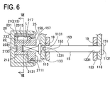
- the pin shaft 15 coaxially includes, as viewed in the order of insertion into the hole 1131, a head 151, a pin portion 153, a rectangular-section portion 155, a flange 157, and a projecting portion 159. They are arranged along the lower edge of the rear opening 31 and the lower end of the lower door 41.
- the head 151 is riveted or swaged in an assembly process of the hinge member 10.
- the pin portion 153 is a shaft having a circular section which rotatably supports the second hinge arm 13 mentioned later via bearings 19.
- the rectangular-section portion 155 is formed to have a square section which is coaxial with the pin portion 153 and has four sides each being slightly larger than the diameter of the pin portion 153.
- the rectangular-section portion 155 is engaged in the rectangular hole 1131 formed in one of the shaft fixing parts 113 to inhibit rotation of the pin shaft 15 relative to the first hinge arm 11.
- the flange 157 is larger in diameter than the rectangular-section portion 155 and serves to fix the pin shaft 15 to the first hinge arm 11 in cooperation with the head 151.
- the projecting portion 159 is formed extending by a predetermined length from the flange 157 in a direction opposite the pin portion 153 and having a rectangular section. Specifically, this projecting portion 159 extends outward of the hinge arms 11 and 13 in such a manner as to engage with the damper 20 mentioned later.
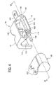
- the second hinge arm 13 has a nearly hat-shaped section as shown in Fig. 4 showing a perspective view of the hinge member 10 corresponding to a closed state of the lower door 41.
- the second hinge arm 13 includes right and left lugs 131 each of which is centrally formed with a hole in which a bolt is tightened for attachment to the lower surface of the lower door 41, bearing portion s 133 spaced at a distance slightly shorter than the distance between the shaft fixing portion s 113 of the first hinge arm 11, and a connecting portion 135 connecting the bearing portion s 133.
- Each bearing portion 133 is formed, at a predetermined position, with a circular through hole 1331 (see Fig. 6 ) through which the pin shaft 15 is inserted interposing the bearing 19.
- the damper 20 includes a rotor 21 connected to the projecting portion 159 of the pin shaft 15, a housing 23 rotatably mounted on the rotor 21 and fixed to the lower door 41, a cap 25 which hermetically closes the housing 21 containing the rotor 21, and a braking means 29 contained in the housing 23 and arranged to impart a braking force to the housing 23 when the housing 23 is rotated relative to the rotor 21.
- the braking means 29 includes an after-mentioned vane 215 formed on the rotor 21, a valve element 217 placed covering the vane 215, and a viscous fluid 299 filled in the housing 23.
- the rotor 21 includes a disc part 211 centrally formed with a connecting rectangular bottomed hole 2131 in which the projecting portion 159 of the pin shaft 15 is engaged, a cylindrical shaft 213 protruding from the disc part 211 to surround the bottom of the rectangular hole 2131, and the vane 215 protruding outward from part of the shaft 213.
- a seal groove 2111 is formed and receives a seal member in slidable contact with the inner periphery of the cap 25.
- the rectangular hole 2131 opens at the outer surface of the disc part 211 and has a depth short of reaching an after-mentioned recess 2133 formed in the shaft 213.
- the circular recess 2133 is formed in the shaft 213 in such a manner as to be opposite the rectangular hole 2131 with respect to the bottom thereof and coaxial with the rectangular hole 2131.
- the vane 215 is formed in plate shape protruding outward from part of the shaft 213 as shown in Fig. 5 so as to have a height perpendicular to the axis, the height being determined by subtracting the thickness of an after-mentioned bottom portion 2175 of the valve element 217 from the diameter of an inner wall surface 2311 of the housing 23.
- the vane 215 is formed with a cutout 2151 in the center of the axial direction.
- the valve element 217 covering the vane 215 includes the bottom portion 2175, and right and left flanges 2171 and 2173 extending downward from the right and left ends of the bottom portion 2175 to provide a U-shape in section.
- the outer surface of the bottom portion 2175 is curved to nearly conform to the inner periphery of the housing 23.
- the right flange 2171 shown in Fig. 5 is formed with a cutout 21711 in the center of the axial direction.
- the valve element 217 is mounted on the vane 215 so that the valve element 217 is slightly movable with a clearance relative to the vane 215 between the right and left flanges 2171 and 2173.
- the housing 23 has a bottomed shape including a cylindrical wall 231, a bottom wall 233 forming the bottom of the cylindrical wall 231, and a fixed vane 235 radially inwardly protruding from the cylindrical wall 231, one end of the fixed vane 235 being continuous to the bottom wall 233 and the other end facing to the opening of the housing 23, and the vane 235 having a height equal to the diameter of the shaft 213 of the rotor 21.
- the inner wall surface 2311 of the cylindrical wall 231 is formed with an eccentric groove 231 having a depth gradually increasing outward from the inner wall surface 2311, the groove 231 being in nearly a diametrically opposite position, as shown in sectional views of Figs. 7 to 9 .
- This eccentric groove 2313 is designed under the following conditions. While the lower door 41 is turned from the almost vertical, full closed position to a full open position at 90° thereto, the sectional area of a clearance "t" between the eccentric groove 2313 and the outer surface of the valve element 217 is maximum as shown in Fig. 7 when the lower door 41 is in a full closed position, the sectional area of the clearance "t” is decreased as the lower door 41 is gradually turned in the opening direction as shown in Figs. 8A to 8C , and the valve element 217 comes to face a portion not provided with the eccentric groove 2313 when the lower door 41 in the full open position ( Fig. 8C ).
- the inner diameter of the inner wall surface 2311 of the cylindrical wall 231 is determined to be almost equal to the outer diameter provided by the outer surface of the valve element 217 when the valve element 217 is mounted to cover the vane 215 of the rotor 21.
- the inner wall surface 2311 is formed, around an opening, with a screw threaded portion which engages with the cap 25 mentioned later.
- the bottom wall 23 is centrally formed with a protrusion 2331 protruding toward the opening at a predetermined height so as to enter in the recess 2133 of the rotor 21.
- the cap 25 is formed in an annular shape having an L-shape in section.
- the disc part 211 of the rotor 21 is hermetically fitted with the seal member inserted in the seal groove 2111.
- the outer surface around the aperture is formed with a male screw threaded portion which engages with the screw threaded portion of the opening area of the inner wall surface 2311 of the housing 23 and a flange portion held in contact with the end face around the opening of the housing 23.
- the damper 20 configured as above is assembled in such a manner as that the rotor 21 with the vane 215 being covered by the valve element 217 is inserted from the shaft 213 side into the housing 23 filled with the viscous fluid 299, the cap 25 is fitted around the disc part 211, causing the viscous fluid 299 to overflow, and then the cap 25 is engaged and tightened in the screw threaded portion formed around the opening of the cylindrical wall 231 of the housing 23.
- stays 237 for attachment of the housing 23 to the lower end of the door 41 are formed protruding in Y-shape in parallel to the central axis.
- the damper 20 is attached to be flush with the lower end of the lower door 41 to which the second hinge arm 13 of the hinge member 10 is attached. Accordingly, the distance from the center of the shaft 213 of the rotor 21 to the outer surfaces of the stays 237 is determined to be equal to the distance from the center of the pin shaft 15 of the second hinge arm 13 to the mounting surfaces of the lugs 131.
- each hinge arm 11 is attached to the floor part 60 and each second hinge arm 13 is attached to the lower end of the lower door 41.
- the damper 20 is mounted on the lower end of the lower door 41 by use of the stays 237 of the damper 20, adjacently to the hinge member 20, when the projecting portion 159 extending from the pin shaft 15 of the hinge member 10, which is placed on the right side in the vehicle traveling direction, toward the center of the vehicle is inserted in the rectangular hole 2131 provided in the center of the rotor 21 of the damper 20.
- those hinge member 10 and damper 20 constitute the vehicle door opening/closing device 1.
- the lower door 41 is provided, as with a conventional structure, with a torsion spring (the same as that in Fig. 10 ) serving as a support means for assisting the power to lift the lower door 41 in order to close the lower door 41 from the full open position, a board 70 disposed to automatically close a gap between the floor part 60 and the lower door 41 when the lower door 41 is fully closed, and others.
- a torsion spring (the same as that in Fig. 10 ) serving as a support means for assisting the power to lift the lower door 41 in order to close the lower door 41 from the full open position
- a board 70 disposed to automatically close a gap between the floor part 60 and the lower door 41 when the lower door 41 is fully closed, and others.
- the housing 23 is in a position where the clearance "t" is large between the eccentric groove 2313 and the valve element 217.
- the oil chambers 27a and 27b partitioned by the rotor 21 and the valve element 215 are communicated to each other through the passage defined by the cutouts 21711 and 2151.
- the viscous fluid 299 is therefore allowed to easily move.
- the housing 23 When the lower door 41 is opened in an arrow direction by 30° from the vertical, closed position, the housing 23 is rotated clockwise 30° relative to the rotor 21 as shown in Fig. 8A .
- the viscous fluid 299 in the oil chamber 27a pushes the left flange 2173 of the valve element 217 rightward. Then, the left flange 2173 comes into contact with the left surface of the vane 215 in the figure to close the cutout 2151 of the vane 215.
- the viscous fluid 299 is therefore not allowed to pass through this cutout 2151.
- the housing 23 is in a position where the clearance "t" between the eccentric groove 2313 and the valve element 217 is smaller. Accordingly, the viscous fluid 299 existing in the oil chamber 27b is allowed to flow in the oil chamber 27a through only the clearance "t". Thus, resistance in opening the lower door 41 is still small.
- the vehicle door opening/closing device of the present embodiment is arranged such that the hinge member 10 includes the first hinge arm 11 fixed to the floor 60, the pin shaft 15 fixed to the first hinge arm 11 and protruding outward of the first hinge arm 11, and the second hinge arm 13 pivotally mounted on the pin shaft 15 and fixed to the lower end of the lower door 41; and the damper 20 includes the rotor 21 connected to the projecting portion 159 of the pin shaft 15, the housing 23 rotatably mounted on the rotor 21 and fixed to the lower door 41, and the braking means 29 contained in the housing 23 and arranged to impart the braking force to the housing 23 when rotated relative to the rotor 21. Since such a hinge member including the pin shaft provided with the projecting portion is used, a simple configuration that the rotor of the damper is connected to the projecting portion can improve an opening and closing feeling of the lower door.
- the present invention is not limited to the above embodiment and may be embodied in other specific forms without departing from the essential characteristics thereof.
- the above embodiment shows the case where the damper is connected to one of the hinge members.
- the damper may be provided for each of the hinge members or only the left one.
- the housing of the damper may be fixed to the floor so that the rotor is rotated in synchronization with the door.
- the eccentric groove of the damper is provided in the housing.
- the shaft of the rotor may be provided with an eccentric groove to control the flow of viscous fluid.
- the present invention is a vehicle door opening/closing device including a hinge member for pivotally connecting a door for opening/closing an opening of a vehicle body to the vehicle body, and a damper for imparting a braking force to the door when the door is turned relative to the vehicle body.
- the hinge member includes a first hinge arm to be attached to one of an edge of the opening and an end of the door facing to each other, a pin shaft fixed to the first hinge arm to be placed along the edge of the opening and the end of the door, and a second hinge arm pivotally mounted on the pin shaft and to be attached to the other of the edge of the opening and the end of the door.
- the damper includes a rotor connected to the pin shaft, a housing rotatably mounted on the rotor and to be attached to the other one of the vehicle body and the door, or, the second hinge arm, and a braking means contained in the housing and arranged to impart a braking force to the housing when the housing is rotated relative to the rotor. Accordingly, the damper is disposed on the axis of the pin shaft of the hinge member between the edge of the opening and the edge of the door.
- the vehicle door opening/closing device that includes the damper which will not interfere with the work of taking in and out baggage and that provides a good appearance can be achieved.
Landscapes
- Engineering & Computer Science (AREA)
- Mechanical Engineering (AREA)
- Fluid-Damping Devices (AREA)
- Closing And Opening Devices For Wings, And Checks For Wings (AREA)
Abstract
Description
- The present invention relates to a door opening/closing device for vehicle and, particularly, to a door opening/closing device provided with a damper for imparting a braking force to a door when the door is turned with respect to a vehicle body.
- As shown in
Fig. 10 , aback door 940 for opening/closing an opening of a vehicle body includes anupper door 945 for opening/closing the upper part of the opening and a lower door 951 for opening/closing the lower part of the opening. Theupper door 945 is pivotally connected, at its upper end, to a rear end of a vehicle roof by an upper hinge so as to be turned upward and downward. Theupper door 945 is flipped up to open the opening.
The lower door 951 is pivotally connected, at its lower end, to a rear end of a vehicle floor by a lower hinge so as to be turned upward and downward. The lower door 951 is turned to a horizontal position to open the opening. - Between the
lower door 941 and the vehicle, there are provided atorsion spring 9415 that urges thelower door 941 in a closing direction to reduce a control force needed for closing thelower door 941 anddampers 9427 for imparting a braking force to thelower door 941 to prevent thelower door 941 from being burst open by its own weight.
Eachdamper 9427 is in the shape of a telescopic rod including a cylinder and a piston rod, the ends of which are connected to a side edge of the opening and a side end of thelower door 941 respectively. - One configuration using the above rod-like damper between the
lower door 941 and the vehicle body is disclosed inJP 1-14112(1989)U Patent Document 1").
[Patent Document 1]JP 1-14112(1989)U - However, the above conventional configuration would cause the following problem. When the
lower door 941 is opened, eachdamper 9427 is stretched between the side end of thelower door 941 and the side edge of the opening, resulting in interference with the work of taking in and out baggage and deterioration of the appearance. - The present invention has been made to solve the above problems and has a purpose to provide a door opening/closing device for vehicle, including a damper that does not interfere with the work of taking in and out baggage and can provide a good appearance.
- A vehicle door opening/closing device set forth in
claim 1 according to the invention is characterized in a vehicle door opening/closing device including a hinge member for pivotally connecting a door for opening and closing an opening of a vehicle body to the vehicle body, and a damper for imparting a braking force to the door when the door is turned relative to the vehicle body, wherein the hinge member includes: a first hinge arm to be attached to one of an edge of the opening and an end of the door facing to each other; a pin shaft fixed to the first hinge arm to be placed along the edge of the opening and the end of the door; and a second hinge arm pivotally mounted on the pin shaft and to be attached to the other one of the edge of the opening and the end of the door, and the damper includes: a rotor connected to the pin shaft; a housing rotatably mounted on the rotor and to be attached to the other one of the vehicle body and the door, or, the second hinge arm; a braking means contained in the housing and arranged to impart a braking force to the housing when the housing is rotated relative to the rotor. - Accordingly, the damper is placed on the axis line of the pin shaft of the hinge member between the edge portion of the opening and the end portion of the door. Thus, the damper will not interfere with the work of taking in and out baggage and can provide a good appearance.
- The door opening/closing device for vehicle set forth in claim 2 of the invention is characterized in that, in the door opening/closing device for vehicle of
claim 1, one end of the pin shaft forms a projecting portion that extends outward of both hinge arms and is connected to the rotor.
Accordingly, a simple structure for connecting the damper to the hinge member can be achieved. - Further, the door opening/closing device for vehicle set forth in claim 3 of the invention is characterized in that, in the door opening/closing device for vehicle of
claim 1 or 2, the hinge member is arranged to connect a lower end of the door to the vehicle body in such a way that the door can be turned upward and downward, and the damper is arranged to increase the braking force as the door is turned in an opening direction.
Accordingly, the braking force is small in the vicinity of the closed position and therefore the door can be opened smoothly. Since the braking force is increased toward the open position, the door can be prevented from being burst open and rattling by its own weight. - According to the door opening/closing device for vehicle of the present invention, the damper will not interfere with the work of taking in and out baggage and can provide a good appearance.
-
-
Fig. 1 is a perspective rear view of a vehicle provided with a vehicle door opening/closing device of a preferred embodiment of the invention, showing an open state of a back door; -
Fig. 2 is a sectional view taken along a line II-II inFig. 1 ; -
Fig. 3 is a sectional view of the same with a lower door closed; -
Fig. 4 is an exploded perspective view of the vehicle door opening/closing device of the embodiment of the invention; -
Fig. 5 is an exploded perspective view of a rotor and a valve element of the vehicle door opening/closing device of the embodiment; -
Fig. 6 is a sectional view taken along a line VI-VI inFig. 4 ; -
Fig. 7 is a sectional view taken along a line VII-VII inFig. 6 ; -
Fig. 8A is a sectional view of the vehicle door opening/closing device of the embodiment of the invention, showing a rotating state of a housing relative to the rotor when the door opens at an angle of 30°; -
Fig. 8B is another sectional view of the vehicle door opening/closing device of the embodiment of the invention, showing a rotating state of the housing relative to the rotor when the door opens at an angle of 60°; -
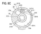
Fig. 8C is another sectional view of the vehicle door opening/closing device of the embodiment of the invention, showing a rotating state of the housing relative to the rotor when the door fully opens at an angle of 90°; -
Fig. 9 is a sectional view of the vehicle door opening/closing device of the embodiment of the invention, showing a state where the door begins to close from a door full open position; and -
Fig. 10 is a view showing an example of a conventional vehicle door opening/closing device using a torsion bar and a gas damper. -
- 1
- Vehicle door opening/closing device
- 10
- Hinge member
- 11
- First hinge arm
- 13
- Second hinge arm
- 15
- Pin shaft
- 159
- Projection
- 20
- Damper
- 21
- Rotor
- 2131
- Rectangular connection hole
- 23
- Housing
- 2313
- Eccentric groove
- 237
- Stay
- 25
- Cap
- 27a, b
- Oil chamber
- 29
- Braking means (Viscous fluid)
- 40
- Back door
- 41
- Lower door
- 45
- Upper door
- 60
- Floor part
- t
- Clearance
- A detailed description of a preferred embodiment of a door opening/closing device for vehicle embodying the present invention will now be given referring to the accompanying drawings.
Fig. 1 is a perspective rear view of a vehicle, showing an open state of a back door;Fig. 2 is a sectional view taken along a line II-II inFig. 1 ; andFig. 3 is a sectional view of the same with a lower door closed. - As shown in
Fig. 1 , arear opening 31 of avehicle body 30 can be opened and closed by aback door 40. Theback door 40 includes anupper door 45 for opening and closing the upper part of therear opening 31 and alower door 41 for opening and closing the lower part of therear opening 31. Theupper door 45 and thelower door 41 are pivotally connected to thevehicle body 30 respectively so as to be opened and closed by a predetermined operation with opening/closing devices. In the present embodiment, a vehicle door opening/closing device 1 according to the present invention is applied to an opening/closing device for thelower door 41. - An opening/closing device for the
upper door 45 is comprised of a hinge member (not shown) for pivotally supporting theupper door 45 so that theupper door 45 can be turn upward and downward relative to thevehicle body 30 anddampers 451 arranged to impart an urging force to theupper door 45 in an opening direction and holding theupper door 45 in the open position.
The hinge member connects aroof part 50 defining the upper edge of therear opening 31 to the upper edge of theupper door 45.
Eachdamper 451 is a gas-filled damper provided with a cylinder and a piston rod arranged to be movable in and out of the cylinder (a so-called gas damper). Eachdamper 451 is connected to one of right and left side ends of theupper door 45 and one of side edges of therear opening 31. - The opening/
closing device 1 for thelower door 41 is comprised of ahinge member 10 for pivotally supporting thelower door 41 so that thelower door 41 can be turned upward and downward relative to thevehicle body 30 and adamper 20 arranged to impart a braking force to thelower door 41 when thelower door 41 is opened in order to prevent thelower door 41 from being burst open by its own weight.
The right and left side ends of thelower door 41 are connected to the side edges of therear opening 31 by wires (not shown). The wires can be tensioned when thelower door 41 is opened to a substantially horizontal open position, thereby holding thelower door 41 in that position. - The
hinge member 10 includes afirst hinge arm 11 fixed to afloor part 60 defining the lower edge of therear opening 31, apin shaft 15 held against rotation by thefirst hinge arm 11, and asecond hinge arm 13 rotatably mounted on thepin shaft 15 and secured to the lower end of thelower door 41, as shown inFigs. 2 to 4 andFig. 6 .
Thefirst hinge arm 11 includes a mountingseat 111 secured to a substantiallyvertical wall 61 of thefloor part 60 with abolt 69, ahorizontal part 115 bent from the upper end of the mountingseat 111 so as to substantially horizontally extend in a direction opposite thevertical wall 61 of thefloor part 60, andflanges 117 bent from right and left end portion s of the mountingseat 111 and thehorizontal part 115 to face each other, forming a U-shape in section. - Each
flange 117 of thehorizontal part 115 further extends in the direction opposite thevertical wall 61 and formed at a predetermined position with a hole 1131 (seeFig. 6 ) through which thepin shaft 15 is inserted, thus forming a semicircular shaft-fixingpart 113 centered on thehole 1131.
Of theholes 1131 of the right and leftshaft fixing parts 113, thehole 1131 on the left side in a vehicle traveling direction has a rectangular shape and theother hole 1131 on the right side has a round shape. - As shown in a sectional view of
Fig. 6 , thepin shaft 15 coaxially includes, as viewed in the order of insertion into thehole 1131, ahead 151, apin portion 153, a rectangular-section portion 155, aflange 157, and a projectingportion 159. They are arranged along the lower edge of therear opening 31 and the lower end of thelower door 41.
Thehead 151 is riveted or swaged in an assembly process of thehinge member 10. Thepin portion 153 is a shaft having a circular section which rotatably supports thesecond hinge arm 13 mentioned later viabearings 19.
The rectangular-section portion 155 is formed to have a square section which is coaxial with thepin portion 153 and has four sides each being slightly larger than the diameter of thepin portion 153. The rectangular-section portion 155 is engaged in therectangular hole 1131 formed in one of theshaft fixing parts 113 to inhibit rotation of thepin shaft 15 relative to thefirst hinge arm 11. - The
flange 157 is larger in diameter than the rectangular-section portion 155 and serves to fix thepin shaft 15 to thefirst hinge arm 11 in cooperation with thehead 151.
The projectingportion 159 is formed extending by a predetermined length from theflange 157 in a direction opposite thepin portion 153 and having a rectangular section. Specifically, this projectingportion 159 extends outward of thehinge arms damper 20 mentioned later. - The
second hinge arm 13 has a nearly hat-shaped section as shown inFig. 4 showing a perspective view of thehinge member 10 corresponding to a closed state of thelower door 41. Thesecond hinge arm 13 includes right and leftlugs 131 each of which is centrally formed with a hole in which a bolt is tightened for attachment to the lower surface of thelower door 41, bearing portion s 133 spaced at a distance slightly shorter than the distance between the shaft fixing portion s 113 of thefirst hinge arm 11, and a connectingportion 135 connecting the bearingportion s 133.
Each bearingportion 133 is formed, at a predetermined position, with a circular through hole 1331 (seeFig. 6 ) through which thepin shaft 15 is inserted interposing thebearing 19. - Next, as shown in
Figs. 4 to 6 , thedamper 20 includes arotor 21 connected to the projectingportion 159 of thepin shaft 15, ahousing 23 rotatably mounted on therotor 21 and fixed to thelower door 41, acap 25 which hermetically closes thehousing 21 containing therotor 21, and a braking means 29 contained in thehousing 23 and arranged to impart a braking force to thehousing 23 when thehousing 23 is rotated relative to therotor 21.
The braking means 29 includes an after-mentionedvane 215 formed on therotor 21, avalve element 217 placed covering thevane 215, and aviscous fluid 299 filled in thehousing 23. - The
rotor 21 includes adisc part 211 centrally formed with a connecting rectangular bottomedhole 2131 in which the projectingportion 159 of thepin shaft 15 is engaged, acylindrical shaft 213 protruding from thedisc part 211 to surround the bottom of therectangular hole 2131, and thevane 215 protruding outward from part of theshaft 213. - On the periphery of the
disc part 211, aseal groove 2111 is formed and receives a seal member in slidable contact with the inner periphery of thecap 25.
Therectangular hole 2131 opens at the outer surface of thedisc part 211 and has a depth short of reaching an after-mentionedrecess 2133 formed in theshaft 213. Thecircular recess 2133 is formed in theshaft 213 in such a manner as to be opposite therectangular hole 2131 with respect to the bottom thereof and coaxial with therectangular hole 2131. - The
vane 215 is formed in plate shape protruding outward from part of theshaft 213 as shown inFig. 5 so as to have a height perpendicular to the axis, the height being determined by subtracting the thickness of an after-mentionedbottom portion 2175 of thevalve element 217 from the diameter of aninner wall surface 2311 of thehousing 23. Thevane 215 is formed with acutout 2151 in the center of the axial direction. - The
valve element 217 covering thevane 215 includes thebottom portion 2175, and right and leftflanges bottom portion 2175 to provide a U-shape in section. The outer surface of thebottom portion 2175 is curved to nearly conform to the inner periphery of thehousing 23. Theright flange 2171 shown inFig. 5 is formed with acutout 21711 in the center of the axial direction.
Thevalve element 217 is mounted on thevane 215 so that thevalve element 217 is slightly movable with a clearance relative to thevane 215 between the right and leftflanges - On the other hand, the
housing 23 has a bottomed shape including acylindrical wall 231, abottom wall 233 forming the bottom of thecylindrical wall 231, and a fixedvane 235 radially inwardly protruding from thecylindrical wall 231, one end of the fixedvane 235 being continuous to thebottom wall 233 and the other end facing to the opening of thehousing 23, and thevane 235 having a height equal to the diameter of theshaft 213 of therotor 21.
Theinner wall surface 2311 of thecylindrical wall 231 is formed with aneccentric groove 231 having a depth gradually increasing outward from theinner wall surface 2311, thegroove 231 being in nearly a diametrically opposite position, as shown in sectional views ofFigs. 7 to 9 . - This
eccentric groove 2313 is designed under the following conditions. While thelower door 41 is turned from the almost vertical, full closed position to a full open position at 90° thereto, the sectional area of a clearance "t" between theeccentric groove 2313 and the outer surface of thevalve element 217 is maximum as shown inFig. 7 when thelower door 41 is in a full closed position, the sectional area of the clearance "t" is decreased as thelower door 41 is gradually turned in the opening direction as shown inFigs. 8A to 8C , and thevalve element 217 comes to face a portion not provided with theeccentric groove 2313 when thelower door 41 in the full open position (Fig. 8C ). - The inner diameter of the
inner wall surface 2311 of thecylindrical wall 231 is determined to be almost equal to the outer diameter provided by the outer surface of thevalve element 217 when thevalve element 217 is mounted to cover thevane 215 of therotor 21. Theinner wall surface 2311 is formed, around an opening, with a screw threaded portion which engages with thecap 25 mentioned later.
Thebottom wall 23 is centrally formed with a protrusion 2331 protruding toward the opening at a predetermined height so as to enter in therecess 2133 of therotor 21. - The
cap 25 is formed in an annular shape having an L-shape in section. In its aperture, thedisc part 211 of therotor 21 is hermetically fitted with the seal member inserted in theseal groove 2111. The outer surface around the aperture is formed with a male screw threaded portion which engages with the screw threaded portion of the opening area of theinner wall surface 2311 of thehousing 23 and a flange portion held in contact with the end face around the opening of thehousing 23. - The
damper 20 configured as above is assembled in such a manner as that therotor 21 with thevane 215 being covered by thevalve element 217 is inserted from theshaft 213 side into thehousing 23 filled with theviscous fluid 299, thecap 25 is fitted around thedisc part 211, causing theviscous fluid 299 to overflow, and then thecap 25 is engaged and tightened in the screw threaded portion formed around the opening of thecylindrical wall 231 of thehousing 23. - On the outer periphery of the
cylindrical wall 231 of thehousing 23, stays 237 for attachment of thehousing 23 to the lower end of thedoor 41 are formed protruding in Y-shape in parallel to the central axis. In the present embodiment, thedamper 20 is attached to be flush with the lower end of thelower door 41 to which thesecond hinge arm 13 of thehinge member 10 is attached. Accordingly, the distance from the center of theshaft 213 of therotor 21 to the outer surfaces of thestays 237 is determined to be equal to the distance from the center of thepin shaft 15 of thesecond hinge arm 13 to the mounting surfaces of thelugs 131. - The above configured
hinge members 10 are mounted side by side at a predetermined spaced interval in such a manner as that eachhinge arm 11 is attached to thefloor part 60 and eachsecond hinge arm 13 is attached to the lower end of thelower door 41. On the other hand, thedamper 20 is mounted on the lower end of thelower door 41 by use of thestays 237 of thedamper 20, adjacently to thehinge member 20, when the projectingportion 159 extending from thepin shaft 15 of thehinge member 10, which is placed on the right side in the vehicle traveling direction, toward the center of the vehicle is inserted in therectangular hole 2131 provided in the center of therotor 21 of thedamper 20. Thus, thosehinge member 10 anddamper 20 constitute the vehicle door opening/closing device 1. - It is to be noted that the
lower door 41 is provided, as with a conventional structure, with a torsion spring (the same as that inFig. 10 ) serving as a support means for assisting the power to lift thelower door 41 in order to close thelower door 41 from the full open position, aboard 70 disposed to automatically close a gap between thefloor part 60 and thelower door 41 when thelower door 41 is fully closed, and others. - Operation of the vehicle door opening/closing device will be explained below. In particular, the explanation will be made with a focus on the operation of the
damper 20 following the door opening and closing.
Therotor 21 of thedamper 20 is connected to the projectingportion 159 of thepin shaft 15 that is fixed to thefirst hinge arm 11 attached to thefloor part 60 of the vehicle. Accordingly, irrespective of the opening/closing operation of thelower door 41, thevane 215 is fixed in an upright position as shown inFig. 7 . - In this state, when the
lower door 41 is returned from the open position shown inFig. 2 to the vertical, closed position shown inFig. 3 , thevalve element 217 is pushed leftward in the figure by theviscous fluid 299 filled in theoil chamber 27b and theright flange 2171 of thevalve element 217 comes into contact with the right surface of thevane 215 inFig. 7 .
Then, thecutout 21711 of theright flange 2171 and thecutout 2151 of thevane 215 are continuous with each other, forming a clearance between theleft flange 2173 and the left surface of thevane 215 to form a flow passage of theviscous fluid 299. - Further, the
housing 23 is in a position where the clearance "t" is large between theeccentric groove 2313 and thevalve element 217. Thus, theoil chambers rotor 21 and thevalve element 215 are communicated to each other through the passage defined by thecutouts viscous fluid 299 is therefore allowed to easily move. - When the
lower door 41 is opened in an arrow direction by 30° from the vertical, closed position, thehousing 23 is rotated clockwise 30° relative to therotor 21 as shown inFig. 8A . Theviscous fluid 299 in theoil chamber 27a pushes theleft flange 2173 of thevalve element 217 rightward. Then, theleft flange 2173 comes into contact with the left surface of thevane 215 in the figure to close thecutout 2151 of thevane 215. Theviscous fluid 299 is therefore not allowed to pass through thiscutout 2151.
However, thehousing 23 is in a position where the clearance "t" between theeccentric groove 2313 and thevalve element 217 is smaller. Accordingly, theviscous fluid 299 existing in theoil chamber 27b is allowed to flow in theoil chamber 27a through only the clearance "t". Thus, resistance in opening thelower door 41 is still small. - When the
lower door 41 is further opened in the arrow direction by 60° from the vertical, closed position, thecutout 2151 of thevane 215 remains closed as shown inFig. 8B and hence theviscous fluid 299 is not allowed to pass through thecutout 2151. Further, the clearance "t" is further smaller, the movement of theviscous fluid 299 from theoil chamber 27b to theoil chamber 27a is gradually restricted. Accordingly, the resistance in opening thelower door 41 is gradually increased. - When the
lower door 41 is opened in the arrow direction from the 60° position to a 90° position, thecutout 2151 of thevane 215 remains closed as shown inFig. 8C and hence theviscous fluid 299 is not allowed to pass through thecutout 2151. The clearance "t" is nearly zero but allows theviscous fluid 299 to barely move through such a little clearance between theinner wall surface 2311 of thehousing 23 and the outer surface of thevalve element 217. The resistance in opening thelower door 41 is therefore increased.
This can brake the opening action (falling-down) of thelower door 41 by its own weight. The opening movement of thelower door 41 in the vicinity of the open position can be made slow. Accordingly, thelower door 41 can be opened softly. - When the
lower door 41 is rotated counterclockwise, like an arrow, from the 90° open position toward the closed position, theright flange 2171 of thevalve element 217 is pushed by theviscous fluid 299 existing in theoil chamber 27b and then comes into contact with the right surface of thevane 215 in the figure, as shown inFig. 9 . Thus, a flow passage is formed between theleft flange 2173 and the left surface of thevane 215 in the figure, allowing communication between theoil chambers
Theviscous fluid 299 existing in theoil chamber 27b is thus allowed to pass through this flow passage to flow in theoil chamber 27a. Accordingly, the resistance in turning thelower door 41 in the closing direction is reduced. Thelower door 41 can be closed easily. - When the
lower door 41 is further turned in the closing direction, the flow passage defined by both thecutouts eccentric groove 2313 and thevalve element 217 is gradually increased. This makes it possible to facilitate the movement of theviscous fluid 299, thereby reducing the resistance in turning thelower door 41 in the closing direction. Thelower door 41 can be closed easily. - As above, the vehicle door opening/closing device of the present embodiment is arranged such that the
hinge member 10 includes thefirst hinge arm 11 fixed to thefloor 60, thepin shaft 15 fixed to thefirst hinge arm 11 and protruding outward of thefirst hinge arm 11, and thesecond hinge arm 13 pivotally mounted on thepin shaft 15 and fixed to the lower end of thelower door 41; and thedamper 20 includes therotor 21 connected to the projectingportion 159 of thepin shaft 15, thehousing 23 rotatably mounted on therotor 21 and fixed to thelower door 41, and the braking means 29 contained in thehousing 23 and arranged to impart the braking force to thehousing 23 when rotated relative to therotor 21. Since such a hinge member including the pin shaft provided with the projecting portion is used, a simple configuration that the rotor of the damper is connected to the projecting portion can improve an opening and closing feeling of the lower door. - The present invention is not limited to the above embodiment and may be embodied in other specific forms without departing from the essential characteristics thereof.
For instance, the above embodiment shows the case where the damper is connected to one of the hinge members. Alternatively, the damper may be provided for each of the hinge members or only the left one.
Further, the housing of the damper may be fixed to the floor so that the rotor is rotated in synchronization with the door.
In the above explanation, the eccentric groove of the damper is provided in the housing. Alternatively, the shaft of the rotor may be provided with an eccentric groove to control the flow of viscous fluid.
Industrial Applicability - The present invention is a vehicle door opening/closing device including a hinge member for pivotally connecting a door for opening/closing an opening of a vehicle body to the vehicle body, and a damper for imparting a braking force to the door when the door is turned relative to the vehicle body. The hinge member includes a first hinge arm to be attached to one of an edge of the opening and an end of the door facing to each other, a pin shaft fixed to the first hinge arm to be placed along the edge of the opening and the end of the door, and a second hinge arm pivotally mounted on the pin shaft and to be attached to the other of the edge of the opening and the end of the door. The damper includes a rotor connected to the pin shaft, a housing rotatably mounted on the rotor and to be attached to the other one of the vehicle body and the door, or, the second hinge arm, and a braking means contained in the housing and arranged to impart a braking force to the housing when the housing is rotated relative to the rotor. Accordingly, the damper is disposed on the axis of the pin shaft of the hinge member between the edge of the opening and the edge of the door. Thus, the vehicle door opening/closing device that includes the damper which will not interfere with the work of taking in and out baggage and that provides a good appearance can be achieved.
Claims (5)
- A vehicle door opening/closing device including a hinge member for pivotally connecting a door for opening and closing an opening of a vehicle body to the vehicle body, and a damper for imparting a braking force to the door when the door is turned relative to the vehicle body,
wherein the hinge member includes:a first hinge arm to be attached to one of an edge of the opening and an end of the door facing to each other;a pin shaft fixed to the first hinge arm to be placed along the edge of the opening and the end of the door; anda second hinge arm pivotally mounted on the pin shaft and to be attached to the other one of the edge of the opening and the end of the door, andthe damper includes:a rotor connected to the pin shaft;a housing rotatably mounted on the rotor and to be attached to the other one of the vehicle body and the door, or, the second hinge arm;a braking means contained in the housing and arranged to impart a braking force to the housing when the housing is rotated relative to the rotor. - The vehicle door opening/closing device according to claim 1, wherein one end of the pin shaft forms a projecting portion that extends outward of both hinge arms and is connected to the rotor.
- The vehicle door opening/closing device according to claim 1, wherein the hinge member is arranged to connect a lower end of the door to the vehicle body in such a way that the door can be turned upward and downward, and the damper is arranged to increase the braking force as the door is turned in an opening direction.
- The vehicle door opening/closing device according to claim 3, wherein the damper includes a cutout formed in a vane of the rotor, and a valve element of a gate shape in section, the valve element covering the vane and having a side surface formed with a cutout in a position facing the cutout of the vane,
the housing internally includes a fixed vane, and
a viscous fluid is filled in the housing. - The vehicle door opening/closing device according to claim 4, wherein the valve element includes a bottom portion having a curved outer surface, and the housing is formed with an eccentric groove in a position facing the outer surface of the bottom portion of the housing.
Applications Claiming Priority (2)
| Application Number | Priority Date | Filing Date | Title |
|---|---|---|---|
| JP2005253042A JP4151687B2 (en) | 2005-09-01 | 2005-09-01 | Vehicle door opening and closing device |
| PCT/JP2006/315637 WO2007029441A1 (en) | 2005-09-01 | 2006-08-08 | Door opening/closing device for vehicle |
Publications (3)
| Publication Number | Publication Date |
|---|---|
| EP1921241A1 true EP1921241A1 (en) | 2008-05-14 |
| EP1921241A4 EP1921241A4 (en) | 2008-08-20 |
| EP1921241B1 EP1921241B1 (en) | 2013-03-20 |
Family
ID=37835566
Family Applications (1)
| Application Number | Title | Priority Date | Filing Date |
|---|---|---|---|
| EP06796316A Ceased EP1921241B1 (en) | 2005-09-01 | 2006-08-08 | Door opening/closing device for vehicle |
Country Status (5)
| Country | Link |
|---|---|
| US (1) | US7866001B2 (en) |
| EP (1) | EP1921241B1 (en) |
| JP (1) | JP4151687B2 (en) |
| CN (1) | CN101253301B (en) |
| WO (1) | WO2007029441A1 (en) |
Cited By (2)
| Publication number | Priority date | Publication date | Assignee | Title |
|---|---|---|---|---|
| RU2541562C2 (en) * | 2013-06-04 | 2015-02-20 | Открытое акционерное общество "Завод им. В.А. Дегтярева" | Special vehicle swivelled board |
| RU184970U1 (en) * | 2018-07-12 | 2018-11-15 | Евгений Станиславович Фокин | FOKIN DEVICE FOR FACILITATION OF LOADING-UNLOADING FROM THE BODY STRUCTURE AND THE TRUCK OF THE LOAD CAR |
Families Citing this family (27)
| Publication number | Priority date | Publication date | Assignee | Title |
|---|---|---|---|---|
| US8117716B2 (en) * | 2006-06-05 | 2012-02-21 | Shiroki Kogyo Co., Ltd. | One-way valve and door check apparatus |
| US7673929B2 (en) * | 2007-10-10 | 2010-03-09 | Ventra Group, Inc. | Hinge with a viscous rotary damper |
| JP5662111B2 (en) * | 2010-11-10 | 2015-01-28 | スガツネ工業株式会社 | Hinge device with damper |
| KR20130115369A (en) * | 2011-01-20 | 2013-10-21 | 존슨 컨트롤즈 인테리얼즈 게엠베하 앤 컴퍼니 케이지 | Movement device for a motor vehicle interior trim part, and interior trim part |
| CN102619074A (en) * | 2011-01-28 | 2012-08-01 | 鸿富锦精密工业(深圳)有限公司 | Hinge structure |
| MX347798B (en) * | 2011-04-12 | 2017-04-27 | Kk Somic Ishikawa | Rotary damper. |
| US9027979B2 (en) | 2011-04-12 | 2015-05-12 | Kabushiki Kaisha Somic Ishikawa | Rotary damper and opening and closing mechanism for a vehicle door |
| JP2015004387A (en) * | 2013-06-19 | 2015-01-08 | 株式会社ソミック石川 | Opening and closing mechanism of rotary damper and vehicle door |
| JP5760812B2 (en) | 2011-07-28 | 2015-08-12 | オイレス工業株式会社 | Rotational speed reducer for truck tailgate |
| US8544930B2 (en) * | 2012-01-27 | 2013-10-01 | Toyota Motor Engineering & Manufacturing North America, Inc. | Tailgate damping systems |
| CN103883190B (en) * | 2014-02-13 | 2016-03-23 | 江苏皓日汽车零部件有限公司 | rear door hinge assembly |
| JP6403592B2 (en) * | 2014-05-02 | 2018-10-10 | 立川ブラインド工業株式会社 | Shielding device |
| JP6355447B2 (en) * | 2014-06-20 | 2018-07-11 | プラス株式会社 | Rotating mechanism and case body using the same |
| WO2016009881A1 (en) * | 2014-07-14 | 2016-01-21 | 立川ブラインド工業株式会社 | Shielding device |
| CN106687658B (en) | 2014-07-14 | 2020-05-15 | 立川窗饰工业株式会社 | Shielding device |
| WO2016009880A1 (en) * | 2014-07-14 | 2016-01-21 | 立川ブラインド工業株式会社 | Shielding device |
| US9725940B2 (en) * | 2014-07-24 | 2017-08-08 | Michael Lambright | Door hinge closing mechanism |
| TWI576497B (en) * | 2015-12-04 | 2017-04-01 | Metal Ind Res And Dev Centre | Multi - stage door resistance device |
| US10253556B2 (en) * | 2016-06-29 | 2019-04-09 | Hunter Douglas Inc. | Damper for a covering for an architectural opening |
| FR3053748B1 (en) * | 2016-07-06 | 2018-07-13 | A Raymond Et Cie | REINFORCED TORSION BAR HING ASSEMBLY |
| US10145164B2 (en) | 2016-10-27 | 2018-12-04 | Ford Global Technologies, Llc | Vehicle tailgate assembly |
| CN108556933A (en) * | 2017-05-03 | 2018-09-21 | 湖北江山专用汽车有限公司 | A kind of freight can expand compartment |
| JP2020180429A (en) * | 2019-04-23 | 2020-11-05 | 株式会社ハイレックスコーポレーション | Opening and closing body drive mechanism |
| US11498626B2 (en) * | 2020-11-11 | 2022-11-15 | Rivian Ip Holdings, Llc | Vehicle tailgate assembly |
| US20240123930A1 (en) * | 2022-10-14 | 2024-04-18 | Rivian Ip Holdings, Llc | Vehicle grille guard and tire carrier |
| CN116641611B (en) * | 2023-06-20 | 2025-11-25 | 重庆长安汽车股份有限公司 | A trunk lid support device, a trunk lid assembly, and a vehicle |
| CN119686600B (en) * | 2024-10-12 | 2025-11-04 | 浙江中劦科技有限公司 | A foldable buffer block for shock absorption in car doors |
Family Cites Families (17)
| Publication number | Priority date | Publication date | Assignee | Title |
|---|---|---|---|---|
| US1970369A (en) * | 1930-06-10 | 1934-08-14 | Nevin S Focht | Hydraulic shock absorber |
| AU624027B2 (en) * | 1989-10-11 | 1992-05-28 | Sugatsune Industrial Co., Ltd | Door hinge |
| JP2581655B2 (en) * | 1991-03-08 | 1997-02-12 | トックベアリング株式会社 | High torque damper |
| US5326093A (en) | 1993-05-24 | 1994-07-05 | Xerox Corporation | Universal interface module interconnecting various copiers and printers with various sheet output processors |
| JP2502042Y2 (en) | 1993-07-14 | 1996-06-19 | トックベアリング株式会社 | Damping hinge |
| JP3008305U (en) * | 1994-08-27 | 1995-03-14 | 加藤電機株式会社 | Opening and closing device for toilet lids and seats of Western style toilets |
| JPH08303514A (en) | 1995-04-28 | 1996-11-19 | Sankyo Seiki Mfg Co Ltd | Rotary damper device |
| US5996132A (en) * | 1997-01-24 | 1999-12-07 | Katoh Electrical Machinery Co., Ltd. | Compound torque hinge |
| JP4573190B2 (en) * | 2001-06-04 | 2010-11-04 | トックベアリング株式会社 | Rotating damper |
| JP3738419B2 (en) | 2001-10-18 | 2006-01-25 | 株式会社大井製作所 | HINGE DEVICE FOR VEHICLE OPENING / CLOSING BODY AND OPENING / CLOSING DEVICE EQUIPPED WITH THIS HINGE DEVICE |
| CN1240952C (en) * | 2002-01-23 | 2006-02-08 | 株式会社三协精机制作所 | Damper device using viscous fluid and method for making same |
| JP3752202B2 (en) | 2002-07-19 | 2006-03-08 | 株式会社ストロベリーコーポレーション | HINGE DEVICE AND ELECTRONIC DEVICE USING HINGE DEVICE |
| JP3990611B2 (en) | 2002-08-22 | 2007-10-17 | 本田技研工業株式会社 | Vehicle rear door structure |
| DE20215983U1 (en) * | 2002-10-17 | 2003-02-27 | Lin, Wu-Shiong, Taichung | door closers |
| JP2005035365A (en) | 2003-07-18 | 2005-02-10 | Daihatsu Motor Co Ltd | Hinge structure for gate for automobile having gate |
| JP4509585B2 (en) * | 2004-01-26 | 2010-07-21 | 株式会社ニフコ | Damper and door handle with this damper |
| DE202006006067U1 (en) * | 2006-04-13 | 2006-06-14 | Edscha Ag | Device for damping the pivoting movement of a door of a motor vehicle comprises a lifting element pivoting in a liquid-filled housing and dividing the housing into a first liquid chamber and a second liquid chamber |
-
2005
- 2005-09-01 JP JP2005253042A patent/JP4151687B2/en not_active Expired - Fee Related
-
2006
- 2006-08-08 EP EP06796316A patent/EP1921241B1/en not_active Ceased
- 2006-08-08 WO PCT/JP2006/315637 patent/WO2007029441A1/en not_active Ceased
- 2006-08-08 CN CN200680031854XA patent/CN101253301B/en not_active Expired - Fee Related
- 2006-08-08 US US11/990,021 patent/US7866001B2/en not_active Expired - Fee Related
Cited By (2)
| Publication number | Priority date | Publication date | Assignee | Title |
|---|---|---|---|---|
| RU2541562C2 (en) * | 2013-06-04 | 2015-02-20 | Открытое акционерное общество "Завод им. В.А. Дегтярева" | Special vehicle swivelled board |
| RU184970U1 (en) * | 2018-07-12 | 2018-11-15 | Евгений Станиславович Фокин | FOKIN DEVICE FOR FACILITATION OF LOADING-UNLOADING FROM THE BODY STRUCTURE AND THE TRUCK OF THE LOAD CAR |
Also Published As
| Publication number | Publication date |
|---|---|
| US20090139057A1 (en) | 2009-06-04 |
| JP2007063884A (en) | 2007-03-15 |
| CN101253301B (en) | 2013-06-19 |
| US7866001B2 (en) | 2011-01-11 |
| EP1921241A4 (en) | 2008-08-20 |
| WO2007029441A1 (en) | 2007-03-15 |
| JP4151687B2 (en) | 2008-09-17 |
| CN101253301A (en) | 2008-08-27 |
| EP1921241B1 (en) | 2013-03-20 |
Similar Documents
| Publication | Publication Date | Title |
|---|---|---|
| EP1921241B1 (en) | Door opening/closing device for vehicle | |
| US5724683A (en) | Hinge mechanism for supporting the seat or the seat lid of a toilet bowl | |
| CA1326251C (en) | Automotive door structure | |
| CA2278840C (en) | Fluid-damped automotive door latch actuator | |
| US5906010A (en) | Operating hinge for seat and seat lid of toilet bowl | |
| AU2010285685B2 (en) | Damper position adjusting device | |
| JP2009535543A (en) | Hinged structures for self-closing doors and other glass doors and the like, and assemblies with such structures | |
| US20050044661A1 (en) | Door-closing device using a cam | |
| KR19980072349A (en) | Automatic Door Closer Unit | |
| FR2755489A1 (en) | HYDRAULIC ANTIVIBRATORY SUPPORT | |
| US20120246875A1 (en) | Door hinge for motor vehicles | |
| JP4308254B2 (en) | Hinge with damper | |
| JPH11247522A (en) | Rotary damper | |
| KR101333385B1 (en) | Cylinder apparatus | |
| JP4470649B2 (en) | Damper and hinge mechanism with damper for automobile door using the same | |
| JP2906316B2 (en) | Rotary damper such as lift hinge | |
| JP3999678B2 (en) | Hinge cartridge and door hinge | |
| KR101253721B1 (en) | Door closing device with multi-function | |
| KR100770425B1 (en) | Damping device for furniture hinge | |
| JP2971607B2 (en) | gas spring | |
| KR200156791Y1 (en) | Hinge for toilet door | |
| JPH03129078A (en) | Door hinge having damper | |
| JP2980616B2 (en) | Seat damper | |
| KR200209589Y1 (en) | Vertical type door closer | |
| EP1113137A1 (en) | Opening and closing mechanism for door |
Legal Events
| Date | Code | Title | Description |
|---|---|---|---|
| PUAI | Public reference made under article 153(3) epc to a published international application that has entered the european phase |
Free format text: ORIGINAL CODE: 0009012 |
|
| 17P | Request for examination filed |
Effective date: 20080206 |
|
| AK | Designated contracting states |
Kind code of ref document: A1 Designated state(s): DE FR GB |
|
| A4 | Supplementary search report drawn up and despatched |
Effective date: 20080723 |
|
| RIC1 | Information provided on ipc code assigned before grant |
Ipc: E05F 5/00 20060101ALI20080717BHEP Ipc: E05F 3/14 20060101ALI20080717BHEP Ipc: B60J 5/10 20060101ALI20080717BHEP Ipc: E05D 7/086 20060101AFI20080407BHEP Ipc: E05F 3/20 20060101ALI20080717BHEP Ipc: B62D 33/027 20060101ALI20080717BHEP |
|
| DAX | Request for extension of the european patent (deleted) | ||
| RBV | Designated contracting states (corrected) |
Designated state(s): DE FR GB |
|
| 17Q | First examination report despatched |
Effective date: 20110729 |
|
| REG | Reference to a national code |
Ref country code: DE Ref legal event code: R079 Ref document number: 602006035215 Country of ref document: DE Free format text: PREVIOUS MAIN CLASS: E05D0007086000 Ipc: E05D0011100000 |
|
| RIC1 | Information provided on ipc code assigned before grant |
Ipc: E05F 5/00 20060101ALI20120509BHEP Ipc: E05F 3/14 20060101ALI20120509BHEP Ipc: E05D 11/10 20060101AFI20120509BHEP Ipc: E05F 3/20 20060101ALI20120509BHEP |
|
| GRAP | Despatch of communication of intention to grant a patent |
Free format text: ORIGINAL CODE: EPIDOSNIGR1 |
|
| GRAS | Grant fee paid |
Free format text: ORIGINAL CODE: EPIDOSNIGR3 |
|
| GRAA | (expected) grant |
Free format text: ORIGINAL CODE: 0009210 |
|
| AK | Designated contracting states |
Kind code of ref document: B1 Designated state(s): DE FR GB |
|
| REG | Reference to a national code |
Ref country code: GB Ref legal event code: FG4D |
|
| REG | Reference to a national code |
Ref country code: DE Ref legal event code: R096 Ref document number: 602006035215 Country of ref document: DE Effective date: 20130508 |
|
| PLBE | No opposition filed within time limit |
Free format text: ORIGINAL CODE: 0009261 |
|
| STAA | Information on the status of an ep patent application or granted ep patent |
Free format text: STATUS: NO OPPOSITION FILED WITHIN TIME LIMIT |
|
| 26N | No opposition filed |
Effective date: 20140102 |
|
| REG | Reference to a national code |
Ref country code: DE Ref legal event code: R097 Ref document number: 602006035215 Country of ref document: DE Effective date: 20140102 |
|
| REG | Reference to a national code |
Ref country code: FR Ref legal event code: PLFP Year of fee payment: 11 |
|
| REG | Reference to a national code |
Ref country code: FR Ref legal event code: PLFP Year of fee payment: 12 |
|
| REG | Reference to a national code |
Ref country code: FR Ref legal event code: PLFP Year of fee payment: 13 |
|
| PGFP | Annual fee paid to national office [announced via postgrant information from national office to epo] |
Ref country code: DE Payment date: 20180724 Year of fee payment: 13 Ref country code: FR Payment date: 20180712 Year of fee payment: 13 |
|
| PGFP | Annual fee paid to national office [announced via postgrant information from national office to epo] |
Ref country code: GB Payment date: 20180808 Year of fee payment: 13 |
|
| REG | Reference to a national code |
Ref country code: DE Ref legal event code: R119 Ref document number: 602006035215 Country of ref document: DE |
|
| GBPC | Gb: european patent ceased through non-payment of renewal fee |
Effective date: 20190808 |
|
| PG25 | Lapsed in a contracting state [announced via postgrant information from national office to epo] |
Ref country code: DE Free format text: LAPSE BECAUSE OF NON-PAYMENT OF DUE FEES Effective date: 20200303 Ref country code: FR Free format text: LAPSE BECAUSE OF NON-PAYMENT OF DUE FEES Effective date: 20190831 |
|
| PG25 | Lapsed in a contracting state [announced via postgrant information from national office to epo] |
Ref country code: GB Free format text: LAPSE BECAUSE OF NON-PAYMENT OF DUE FEES Effective date: 20190808 |