EP1921212A2 - Verfahren und Vorrichtung zur Beseitigung unterirdischer Hindernisse und Messer zur Verwendung für eine derartige Vorrichtung - Google Patents
Verfahren und Vorrichtung zur Beseitigung unterirdischer Hindernisse und Messer zur Verwendung für eine derartige Vorrichtung Download PDFInfo
- Publication number
- EP1921212A2 EP1921212A2 EP07111699A EP07111699A EP1921212A2 EP 1921212 A2 EP1921212 A2 EP 1921212A2 EP 07111699 A EP07111699 A EP 07111699A EP 07111699 A EP07111699 A EP 07111699A EP 1921212 A2 EP1921212 A2 EP 1921212A2
- Authority
- EP
- European Patent Office
- Prior art keywords
- knife
- cutting edge
- obstacles
- disposing
- sawteeth
- Prior art date
- Legal status (The legal status is an assumption and is not a legal conclusion. Google has not performed a legal analysis and makes no representation as to the accuracy of the status listed.)
- Withdrawn
Links
- JSMRMEYFZHIPJV-UHFFFAOYSA-N C1C2CCC1C2 Chemical compound C1C2CCC1C2 JSMRMEYFZHIPJV-UHFFFAOYSA-N 0.000 description 1
Images

Classifications
-
- A—HUMAN NECESSITIES
- A01—AGRICULTURE; FORESTRY; ANIMAL HUSBANDRY; HUNTING; TRAPPING; FISHING
- A01B—SOIL WORKING IN AGRICULTURE OR FORESTRY; PARTS, DETAILS, OR ACCESSORIES OF AGRICULTURAL MACHINES OR IMPLEMENTS, IN GENERAL
- A01B79/00—Methods for working soil
-
- A—HUMAN NECESSITIES
- A01—AGRICULTURE; FORESTRY; ANIMAL HUSBANDRY; HUNTING; TRAPPING; FISHING
- A01B—SOIL WORKING IN AGRICULTURE OR FORESTRY; PARTS, DETAILS, OR ACCESSORIES OF AGRICULTURAL MACHINES OR IMPLEMENTS, IN GENERAL
- A01B35/00—Other machines for working soil not specially adapted for working soil on which crops are growing
- A01B35/02—Other machines for working soil not specially adapted for working soil on which crops are growing with non-rotating tools
-
- A—HUMAN NECESSITIES
- A01—AGRICULTURE; FORESTRY; ANIMAL HUSBANDRY; HUNTING; TRAPPING; FISHING
- A01G—HORTICULTURE; CULTIVATION OF VEGETABLES, FLOWERS, RICE, FRUIT, VINES, HOPS OR SEAWEED; FORESTRY; WATERING
- A01G23/00—Forestry
- A01G23/02—Transplanting, uprooting, felling or delimbing trees
- A01G23/06—Uprooting or pulling up trees; Extracting or eliminating stumps
-
- E—FIXED CONSTRUCTIONS
- E02—HYDRAULIC ENGINEERING; FOUNDATIONS; SOIL SHIFTING
- E02F—DREDGING; SOIL-SHIFTING
- E02F5/00—Dredgers or soil-shifting machines for special purposes
- E02F5/30—Auxiliary apparatus, e.g. for thawing, cracking, blowing-up, or other preparatory treatment of the soil
- E02F5/32—Rippers
Definitions
- the invention relates to a method for disposing of underground obstacles, such as roots and/or tree-stumps, wherein an at least substantially sickle-like knife provided on both sides with a cutting edge is attached to an excavator arm of an excavating machine, whereafter the knife is moved through the ground.
- underground obstacles such as roots and/or tree-stumps
- a very favourable realization of the inventive method has the feature that a concave cutting edge of the knife is provided with sawteeth, and that obstacles are at least partially sawn through using sawing movements performed by the excavator arm.
- a further favourable realization has the feature that a convex cutting edge of the knife is provided with serrations, and that at least partially sawn-through obstacles are pulled loose using pulling and pushing movements performed by the excavator arm.
- the invention also relates to a device for disposing of underground obstacles, such as tree roots, comprising an excavating machine provided with a coupling member and a coupling plate.
- the inventive device has the feature that the coupling plate is provided with at least one at least substantially sickle-like knife provided on both sides with a cutting edge. Using the knife the underground obstacles are pulled to pieces or cut through, whereafter an excavator bucket can be coupled to the coupling member and the parts of the underground obstacle that have been pulled to pieces or cut into pieces can easily be removed.
- a favourable embodiment of the inventive device has the feature that the knife is provided with a welded-on flange provided with fixing holes, so that the knife can easily be fitted or replaced with a knife of another type.
- the knife is preferably provided in at least two welded-on shoring plates for lateral support of the knife.
- a further, very favourable embodiment of the inventive device has the feature that a concave cutting edge is provided with sawteeth. It is then possible to saw at least partially into even very thick roots by causing the excavator arm of the excavating machine to perform several sawing movements. Furthermore, a convex cutting edge is then preferably provided with serrations which take a much larger form than the sawteeth. Using these serrations a partly sawn-through root can then be pulled to pieces in simple manner by causing the excavator arm to perform a pulling movement.
- a further favourable embodiment of the inventive method has the feature that the sawteeth and the serrations are at least substantially of symmetrical form, so that sawing movements and pulling movements can effectively be carried out in two directions.
- the invention also relates to a knife for disposing of roots and/or tree-stumps for use in a device as specified in the foregoing paragraphs.
- the knife herein has dimensions which are chosen in proportion to the excavating machine. For a so-called mini-excavator a knife with a length of for instance 45 cm can be utilized, and for large excavating machines the length can amount to for instance 150 cm.
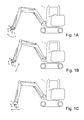
- Fig. 1 shows a schematically a mini-excavator 1 equipped with a knife 2 according to the invention.
- Mini-excavator 1 is provided with a coupling member 3, here shown schematically, which can generally be embodied differently for different mini-excavators, and knife 2 is mounted removably on a coupling plate 4 which is generally supplied by the supplier of the mini-excavator.
- knife 2 makes a cutting movement which suffices to cut through relatively thin roots present in the ground.
- Fig. 1 B knife 2 makes a sawing movement with which it is possible to effectively saw through or saw into relatively thick roots present in the ground. If relatively thick roots must be removed, a knife 2 is preferably mounted that is provided with sawteeth.
- Fig. 1 shows a schematically a mini-excavator 1 equipped with a knife 2 according to the invention.
- Mini-excavator 1 is provided with a coupling member 3, here shown schematically, which can generally be embodied differently for different mini-excav
- knife 2 makes a pulling movement.
- knife 2 is provided with a serrated edge 5 with coarse teeth with which for instance a partially sawn-through root can be pulled to pieces.
- coupling plate 4 is then uncoupled and a standard excavator bucket is attached with which the root parts with adhering soil can be removed.
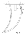
- Knife 2 is provided with a concave cutting edge 6 which is provided here with a smooth cutting face, and a convex cutting edge 7 which is likewise provided with a smooth cutting face which, however, is provided on the upper part with a serrated edge 5 with coarse teeth suitable for penetrating into a root and providing sufficient grip for the purpose of pulling apart this root using mini-excavator 1.
- a welded-on flange 8 provided with fixing holes 9a,9b,9c,9d, of which only fixing holes 9a,9b are visible in this figure, with which the flange 8 can be fixed to coupling plate 4.
- two welded-on shoring plates 10a,10b of which only shoring plate 10a is visible in this figure, which laterally support the knife 2.
- Knife 2 is provided with a concave cutting edge 6 which is here provided with a row of sawteeth 11 suitable for sawing through a root using mini-excavator 1.
- Knife 2 is for instance manufactured from carbon steel and the teeth are hardened in a per se known manner, although it is also possible to embed in knife 2 in a per se known manner a row of teeth manufactured from tungsten or widia or other very hard material.
- Knife 2 is further provided with a convex cutting edge 7 with a smooth cutting face which is provided at the top with a serrated age 5 with coarse teeth suitable for penetrating into a root and providing sufficient grip to pull this root to pieces using mini-excavator 1.
- a welded-on flange 8 provided with fixing holes 9a,9b,9c,9d, of which only fixing holes 9a,9b are visible in this figure, with which flange 8 can be fixed to coupling plate 4.
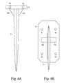
- Fig. 4A shows in more detail a front view of a possible embodiment of a knife 2 according to the invention, with concave cutting edge 6, in addition to welded-on flange 8, holes 9a,9b,9c,9d and welded-on shoring plates 10a,10b.
- Fig. 4B shows in more detail a bottom view of a possible embodiment of a knife 2 according to the invention, with concave cutting edge 6, in addition to welded-on flange 8, holes 9a,9b,9c,9d and welded-on shoring plates 10a,10b.
- a relatively large knife is then for instance mounted on coupling plate 4, flanked by two smaller knives which are preferably placed slightly behind the relatively large knife. The relatively large knife then severs the roots, whereafter the relatively small knives pull the root parts out of the ground.
- a coupling plate can herein be mounted on a lifting device of a tractor, whereafter the tractor removes the root parts from the ground as it travels.
- a tubular frame, on which the knives are mounted, can also be utilized instead of a coupling plate.
- such a coupling plate can advantageously be utilized for the purpose of cutting open solidly compacted ground possibly mixed with manure, as for instance found at riding stables.
Applications Claiming Priority (1)
| Application Number | Priority Date | Filing Date | Title |
|---|---|---|---|
| NL1032857A NL1032857C1 (nl) | 2006-11-13 | 2006-11-13 | Werkwijze en inrichting voor het ruimen van ondergrondse obstakels, alsmede een mes voor gebruik bij een dergelijke inrichting. |
Publications (2)
| Publication Number | Publication Date |
|---|---|
| EP1921212A2 true EP1921212A2 (de) | 2008-05-14 |
| EP1921212A3 EP1921212A3 (de) | 2009-05-13 |
Family
ID=37964463
Family Applications (1)
| Application Number | Title | Priority Date | Filing Date |
|---|---|---|---|
| EP07111699A Withdrawn EP1921212A3 (de) | 2006-11-13 | 2007-07-04 | Verfahren und Vorrichtung zur Beseitigung unterirdischer Hindernisse und Messer zur Verwendung für eine derartige Vorrichtung |
Country Status (2)
| Country | Link |
|---|---|
| EP (1) | EP1921212A3 (de) |
| NL (1) | NL1032857C1 (de) |
Cited By (1)
| Publication number | Priority date | Publication date | Assignee | Title |
|---|---|---|---|---|
| WO2009149696A2 (de) | 2008-06-10 | 2009-12-17 | Hartmut Neidlein | Rodungsmesser |
Families Citing this family (1)
| Publication number | Priority date | Publication date | Assignee | Title |
|---|---|---|---|---|
| CN108729488A (zh) * | 2018-05-31 | 2018-11-02 | 淮北卓颂建筑工程有限公司 | 一种松土装置中的开松部件 |
Citations (4)
| Publication number | Priority date | Publication date | Assignee | Title |
|---|---|---|---|---|
| US2642791A (en) * | 1948-09-20 | 1953-06-23 | George W Peacock Jr | Detachable root cutter |
| EP0314591A1 (de) * | 1987-10-28 | 1989-05-03 | Jean-Marie Plaisance | Stumpfrodegerät |
| CA2181629A1 (en) * | 1995-07-20 | 1997-01-21 | John M. Petersen | Apparatus and method for tree stump clearing |
| FR2840508A1 (fr) * | 2002-06-05 | 2003-12-12 | Jean Louis Galharret | Dispositif de dessouchage, notamment utilisable en lieux difficiles d'acces et procede de mise en oeuvre |
-
2006
- 2006-11-13 NL NL1032857A patent/NL1032857C1/nl not_active IP Right Cessation
-
2007
- 2007-07-04 EP EP07111699A patent/EP1921212A3/de not_active Withdrawn
Patent Citations (4)
| Publication number | Priority date | Publication date | Assignee | Title |
|---|---|---|---|---|
| US2642791A (en) * | 1948-09-20 | 1953-06-23 | George W Peacock Jr | Detachable root cutter |
| EP0314591A1 (de) * | 1987-10-28 | 1989-05-03 | Jean-Marie Plaisance | Stumpfrodegerät |
| CA2181629A1 (en) * | 1995-07-20 | 1997-01-21 | John M. Petersen | Apparatus and method for tree stump clearing |
| FR2840508A1 (fr) * | 2002-06-05 | 2003-12-12 | Jean Louis Galharret | Dispositif de dessouchage, notamment utilisable en lieux difficiles d'acces et procede de mise en oeuvre |
Cited By (2)
| Publication number | Priority date | Publication date | Assignee | Title |
|---|---|---|---|---|
| WO2009149696A2 (de) | 2008-06-10 | 2009-12-17 | Hartmut Neidlein | Rodungsmesser |
| WO2009149696A3 (de) * | 2008-06-10 | 2010-02-18 | Hartmut Neidlein | Rodungsmesser |
Also Published As
| Publication number | Publication date |
|---|---|
| NL1032857C1 (nl) | 2007-02-20 |
| EP1921212A3 (de) | 2009-05-13 |
Similar Documents
| Publication | Publication Date | Title |
|---|---|---|
| US20060156590A1 (en) | Tree root pruning apparatus and method of use | |
| US5921302A (en) | Method and apparatus for tree stump clearing | |
| US5490340A (en) | Root grubber | |
| US7415999B1 (en) | Tree grubber and push bar attachment device | |
| US2309223A (en) | Brush cutter | |
| US6490815B1 (en) | Excavator bucket with ripping implement | |
| AU2004213014B2 (en) | Subsoiling grapple rake | |
| CA2515960C (en) | Subsoiling excavator bucket | |
| EP1921212A2 (de) | Verfahren und Vorrichtung zur Beseitigung unterirdischer Hindernisse und Messer zur Verwendung für eine derartige Vorrichtung | |
| US7520306B1 (en) | Tree remover | |
| US20030014886A1 (en) | Tree and stump removal | |
| US9185855B2 (en) | Tree removal—field reclamation attachment | |
| CA2271619C (en) | Root cutter tool | |
| US20150216100A1 (en) | Cutting Device | |
| KR101716364B1 (ko) | 굴삭기용 삽 | |
| US9043963B2 (en) | Tree stump excavation tool | |
| CA2621691A1 (en) | Soil fracturing tool | |
| KR101879443B1 (ko) | 조경수 굴취겸용 다기능 단근장치 | |
| KR101269133B1 (ko) | 수목 이식용 굴취장치 | |
| CN203027707U (zh) | 翼铲式马铃薯挖掘机 | |
| US20020104237A1 (en) | Tree and stump removal | |
| US20060283055A1 (en) | Subsoiling brush cutter hitch | |
| CN103518484B (zh) | 一种茯苓挖掘机 | |
| CN2401013Y (zh) | 起蒜器 | |
| JPH0615453U (ja) | 植木移植用掘削バケット |
Legal Events
| Date | Code | Title | Description |
|---|---|---|---|
| PUAI | Public reference made under article 153(3) epc to a published international application that has entered the european phase |
Free format text: ORIGINAL CODE: 0009012 |
|
| AK | Designated contracting states |
Kind code of ref document: A2 Designated state(s): AT BE BG CH CY CZ DE DK EE ES FI FR GB GR HU IE IS IT LI LT LU LV MC MT NL PL PT RO SE SI SK TR |
|
| AX | Request for extension of the european patent |
Extension state: AL BA HR MK RS |
|
| PUAL | Search report despatched |
Free format text: ORIGINAL CODE: 0009013 |
|
| AK | Designated contracting states |
Kind code of ref document: A3 Designated state(s): AT BE BG CH CY CZ DE DK EE ES FI FR GB GR HU IE IS IT LI LT LU LV MC MT NL PL PT RO SE SI SK TR |
|
| AX | Request for extension of the european patent |
Extension state: AL BA HR MK RS |
|
| AKX | Designation fees paid | ||
| REG | Reference to a national code |
Ref country code: DE Ref legal event code: 8566 |
|
| STAA | Information on the status of an ep patent application or granted ep patent |
Free format text: STATUS: THE APPLICATION IS DEEMED TO BE WITHDRAWN |
|
| 18D | Application deemed to be withdrawn |
Effective date: 20091116 |