EP1920232B1 - Systeme permettant de detecter et d'analyser des dechets biologiques repandus dans un sous-vetement - Google Patents
Systeme permettant de detecter et d'analyser des dechets biologiques repandus dans un sous-vetement Download PDFInfo
- Publication number
- EP1920232B1 EP1920232B1 EP06758508A EP06758508A EP1920232B1 EP 1920232 B1 EP1920232 B1 EP 1920232B1 EP 06758508 A EP06758508 A EP 06758508A EP 06758508 A EP06758508 A EP 06758508A EP 1920232 B1 EP1920232 B1 EP 1920232B1
- Authority
- EP
- European Patent Office
- Prior art keywords
- mannequin
- sensors
- excretory product
- undergarment
- photodiode
- Prior art date
- Legal status (The legal status is an assumption and is not a legal conclusion. Google has not performed a legal analysis and makes no representation as to the accuracy of the status listed.)
- Expired - Lifetime
Links
Images




Classifications
-
- G—PHYSICS
- G01—MEASURING; TESTING
- G01N—INVESTIGATING OR ANALYSING MATERIALS BY DETERMINING THEIR CHEMICAL OR PHYSICAL PROPERTIES
- G01N33/00—Investigating or analysing materials by specific methods not covered by groups G01N1/00 - G01N31/00
- G01N33/48—Biological material, e.g. blood, urine; Haemocytometers
- G01N33/483—Physical analysis of biological material
- G01N33/487—Physical analysis of biological material of liquid biological material
- G01N33/493—Physical analysis of biological material of liquid biological material urine
-
- G—PHYSICS
- G09—EDUCATION; CRYPTOGRAPHY; DISPLAY; ADVERTISING; SEALS
- G09B—EDUCATIONAL OR DEMONSTRATION APPLIANCES; APPLIANCES FOR TEACHING, OR COMMUNICATING WITH, THE BLIND, DEAF OR MUTE; MODELS; PLANETARIA; GLOBES; MAPS; DIAGRAMS
- G09B19/00—Teaching not covered by other main groups of this subclass
-
- G—PHYSICS
- G09—EDUCATION; CRYPTOGRAPHY; DISPLAY; ADVERTISING; SEALS
- G09B—EDUCATIONAL OR DEMONSTRATION APPLIANCES; APPLIANCES FOR TEACHING, OR COMMUNICATING WITH, THE BLIND, DEAF OR MUTE; MODELS; PLANETARIA; GLOBES; MAPS; DIAGRAMS
- G09B23/00—Models for scientific, medical, or mathematical purposes, e.g. full-sized devices for demonstration purposes
- G09B23/28—Models for scientific, medical, or mathematical purposes, e.g. full-sized devices for demonstration purposes for medicine
Definitions
- Some bench measurement methods have targeted BM spread in static mannequins.
- the undergarment product is placed on a static mannequin and insulted with a BM simulant. Allowing for dwell time, the undergarment product is removed from the mannequin for inspection.
- the inspection is typically performed visually or by photographic records, which does not provide a real-time measure of BM spread.
- analyses of visual and photographic data recorded in these measurements are often time intensive and tedious.
- Video imaging within the undergarment is problematic for several reasons.
- a skeleton has to be employed to support the mannequin skin. Such a skeleton will interfere with imaging and limit space for camera placement.
- Identifying a sensing technology for real-time BM spread requires analysis of features of a system that can be sensed.
- a component lending itself to detection is the BM simulant.
- the BM simulant can be sensed by fluid conductivity or interruption of a sensed parameter. Both of these techniques are inherently discrete, which requires several sensors to simultaneously respond over a finite area to detect position of the BM simulant.
- the BM simulant would have to physically flow between two conducting materials. The conductive fluid would complete a circuit and single that the BM simulant is present in a particular position. Conductivity measurement, however, is problematic in a skin surface sensor array for a variety of reasons.
- a system is needed in the industry for real-time detection and spread analysis of biological waste in an undergarment.
- US 2004/0118224 A1 discloses a prior art system and method for evaluating materials for use in absorbent articles. The method comprises placing the material proximate a simulated skin substrate, insulting the material with a fluid and, after a predetermined time, taking fluid loss measurements. US 2004/0118224 A1 discloses the features of the preambles of claims 1 and 13.
- EP 0 887 055 A1 discloses a prior art method of monitoring the humidity within an absorbent article after an insult.
- the present invention provides a detection and analysis system using a mannequin motion system equipped with a sensor that senses a parameter.
- the parameter is interrupted by a biological waste spread to detect and analyzed the spread in real-time.
- the component parts of the detection and analysis system are simple and economical to manufacture, assemble and use. Other advantages of the invention will be apparent from the following description and the attached drawings, or can be learned through practice of the invention.
- biological waste includes a simulated excrement, a simulated excretory product, a simulated exudate, a simulated bowel movement (BM), simulated feces, simulated urine, simulated menses, simulated blood and any other simulated human waste excretion.
- BM simulated bowel movement
- simulated and simulant are used to refer to any manufactured materials, objects and fluids and can mean virtual, artificial, synthetic and the like.
- undergarment means any diaper, childcare, feminine care, adult care, healthcare or other undergarment.
- a system for analyzing biological waste in an undergarment is provided, as set forth in claim 1.
- the mannequin simulates human motion in order to better simulate biological waste spread such as when a toddler walks around a room.
- the evacuation port of the mannequin can simulate a human anus with the excretory product being a feces simulant for elimination through the simulated anus.
- an insult port can be provided for insulting simulated human urine from the mannequin into the undergarment is provided.
- At least one of the sensors in this aspect of the invention is a photodiode disposed in the skin surface of the mannequin.
- a light source can be located about the mannequin to produce the light emission to activate the photodiode.
- the photodiode senses a light emission external to the skin surface and signals the computer when the excretory product is affecting the light emission.
- the photodiode can be substantially flush with the skin surface, and is disposed under a transparent polymer coating, which itself is coated on the skin surface.
- the excretory product can be opaque in appearance to block the light emission, but it can also be translucent to alter the light emission.
- the simulated human urine can include a darkening agent to affect sensing by the sensors.
- At least one of the sensors in this aspect of the invention can be a heat sensor disposed in the mannequin at least partially exposed to an ambient environment.
- the heat sensor senses a presence of the excretory product when a temperature of the excretory product is greater than an ambient temperature in the ambient environment.
- At least one of the sensors can also be a humidity sensor disposed in the mannequin.
- the humidity sensor senses a humidity of the excretory product.
- the computer records the dispersion pattern being produced by the excretory product being sensed by the sensors.
- the computer includes means for replaying the recorded dispersion pattern for a user to analyze the dispersion pattern being formed in real-time.
- the system can include means for programming the computer to convert the excretory product into the dispersion pattern.
- the means for programming can be a software program configured to record the dispersion pattern in real-time and replay the dispersion pattern for analysis.
- the method can also include the step of injecting a darkening agent in the excretory product such that the excretory product exhibits an opaque appearance to block the emission.
- the method can also accommodate the step of placing the mannequin in motion while the excretory product is being eliminated from the evacuation port into the undergarment.
- a detection and analysis system is provided with sensors that sense a parameter, which can be interrupted by a simulated biological waste in an undergarment for detection and analysis of a spread of the simulated biological waste.
- the detection and analysis system broadly includes a mannequin motion system with a movable mannequin connected to a movement controller within a light box.
- the mannequin is in electronic communication with a computer for relaying collected data relative to the mannequin.
- FIGS. 1-5 A first embodiment of a detection and analysis system, designated in general by the element number 10, is shown in FIGS. 1-5 .
- the detection and analysis system 10 broadly includes a mannequin motion system 12, a computer 14, a light box 16, a mannequin 18 and a controller 20.
- the mannequin 18 is electrically connected to the computer 14 and the controller 20 within the light box 16.
- An undergarment U (shown in phantom for clarity) is attached to the mannequin 18 in a known manner and a simulated biological waste product B is insulted through the mannequin 18 into the undergarment U.
- a number of sensors such as photodiodes 40 are embedded in or located near a surface or simulated skin 22 of the mannequin 18. As the biological waste B passes over the photodiodes 40, the photodiodes 40 register the presence of the biological waste B due to an attenuation of incoming light that is normally received by the photodiodes 40. Further details of the photodiodes and alternative sensors as well as other components of the detection and analysis system 10, its material makeup, arrangement and examples of its operation are provided in greater detail below.
- the detection and analysis system 10 utilizes the light box 16 with a plurality of sensors such as photodiodes 40a-x (where x represents a theoretically limitless number of photodiodes), which are situated in the mannequin 18.
- a plurality of heat sensors 56a-x and humidity sensors 60a-x can be used by the detection and analysis system 10.
- the mannequin 18 is positioned within the light box 16, which includes three walls 16A-C, a ceiling 16D, a floor 16E and a door 16F.
- the mannequin 18 includes a simulated skin 22 and forms a torso 18A and left and right legs 18B,C.
- the mannequin 18 also includes an evacuation port 26 (alternatively, insult port or aperture) defined through the simulated skin 22.
- the legs 18A,B are connected to the controller 20 to control movement of the mannequin 18 as will be described below.
- a biological waste simulant container 36 is connected to the mannequin 18 via a tube 24 that extends to the evacuation port 26.
- the mannequin 18 is also connected to the computer 14 and a data acquisition card (DAQ) 30.
- the DAQ 30 collects data on the simulated biological waste B spread in the undergarment U and displays that data on a display 28 as will be described below.
- DAQ data acquisition card
- FIGURE 1 further shows a plurality of mounted light fixtures 32a-x (where x represents a theoretically unlimited number of fixtures). Also shown, at least two mobile fixtures 34a,b known as “trouble lights” can be positioned as desired to change an emission of light rays L or intensity relative to certain aspects of the mannequin 18.
- FIGURE 1 also illustrates potential directions of motion by the legs 18A,B via the controller 20 as indicated by the bold arrows labeled M.
- FIGURE 2 a portion of the detection and analysis system 10 is shown schematically.
- the computer 14 is interfaced to a multiplexer 42 such as a four slot SCXI series chassis available from National Instruments Corporation, Austin, Texas.
- a multiplexer 42 such as a four slot SCXI series chassis available from National Instruments Corporation, Austin, Texas.
- four (4) photodiode arrays 38a-d, each having thirty-two photodiodes 40a-x are interfaced to respective modules 44a-d, which are connected to the multiplexer 42.
- the DAQ 30 is an NI PCI-6036e card also available from National Instruments Corporation.
- the National Instruments DAQ and related system is suitable due to flexibility, expandability, accuracy and programming ease.
- the NI PCI-6036e card provides sixteen-bit accuracy (greater than 65,000 levels) on analog inputs at 200-kilo samples/second.
- a signal conditioning/multiplexing chassis, the multiplexer 42 is used to expand the range of the DAQ 30 in this exemplary set up.
- the DAQ 30 of the detection and analysis system 10 is not limited to the NI PCI-6036e card, which is an example only.
- use of a greater capacity acquisition card that allows more than sixteen single-ended or eight differential inputs can eliminate the need for the multiplexer 42 as used in this example.
- the multiplexer 42 is shown loaded with the four modules 44A-D.
- the modules 44A-D are each SCXI-1032 channel analog input modules that provide a total of 128 analog input channels.
- the 128 channels are multiplexed by the multiplexer 42 to the DAQ card 30 channels through the multiplexer 42.
- the modules 44A-D are connectible to the photodiode arrays 38A-D through removable shielded terminal blocks (not shown).
- FIGURE 2 further shows the plurality of heat sensors 56a-x and humidity sensors 60a-x briefly introduced above.
- a heat sensor array 54 includes the plurality of heat sensors 56a-x.
- the heat sensors 56a-x are interfaced to one of the modules 44a-d, which are connected to the multiplexer 42 as described above.
- a humidity sensor array 58 includes the plurality of humidity sensors 60a-x, which is also connected to the multiplexer 42.
- FIGURE 2 For clarity, only one heat sensor array 54 and only one humidity sensor array 58 are shown in FIGURE 2 , but those skilled in the art will recognize that multiple arrays, each containing multiple sensors, can be employed in the detection and analysis system 10.
- the heat sensors 56a-x and the humidity sensors 60a-x can be physically arranged on, in or about the mannequin 18 for sensing heat and humidity, respectively, in real time in a manner similar to the photodiodes 40a-x as discussed below.
- the mannequin 18 is more particularly shown connected to the controller 20 and the multiplexer 42, which are powered by a power supply 46.
- a plurality of recesses 22a-x are defined in the simulated skin 22 of the mannequin 18.
- the simulated skin 22 is a polymer although various elastomeric materials can be used, which have sufficient extensibility and elastic recovery properties.
- a plurality of electrical connecting wires 45 is used to connect the sensors such as the photodiodes 40a-x to the modules 44a-x, which are connected to the multiplexer 42.
- the wires 45 can be two-conductor, sealed wire obtained from manufacturers such as Bay Associates of Menlo Park, California, which can custom create the wires 45 to be small, flexible 36 AWG gauge wire.
- the legs 18B,C are connected by cables/serial ports 47 to the computer 14 as known to the skilled artisan, and the electrical connecting wires 45 connect the controller 20 to the power supply 46 to control movement of the mannequin 18.
- the recesses 22a-x are used to position the photodiodes 40a-x, the heat sensors 56a-x, and the humidity sensors 60a-x, as well as other sensors and combinations of these sensors, in or on the mannequin 18.
- the evacuation port 26 can be a simulated anus 26A or a simulated urethra 26B.
- a protective compound or covering 48 is used to coat the mannequin 18.
- the covering 48 can be a silicone rubber compound such as Dragon SkinTM brand available from Smooth On, Inc. Such a silicone rubber compound is also durable and flexible, which is useful for repetitive motions when the mannequin 18 is put into motion by the controller 20.
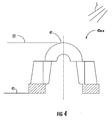
- the photodiode 40a-x includes an N and P type silicone sandwiched together for exposure to ambient lighting such as the mounted fixtures 32a-x and mobile fixtures 34A,B as described above.
- the photodiodes 40 each have a lens 41 for passage of the light rays L.
- the lens 41 is located near the skin surface 22 as described above.
- a reverse bias voltage is applied to the photodiode 40, a "depletion region" (lack of electrical charge) is created in the PN junction.
- an electron hole pair is created.
- the electron hole pair separate with an electron entering the N-type silicone and the hole entering the P-type, which results in a current generated by the light rays incident upon the photodiode 40. Migration of holes and electrons to their respective regions is known as the photovoltaic effect.
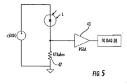
- a basic circuit to read a current from the photodiode 40a-x is shown.
- the light rays L reach the lens 41 of the photodiode 40a-x to allow current to flow that is proportional to intensity and wavelength of the light rays L.
- the input to a programmable gain instrumentation amp (PGIA) 43 located on the analog input module has relatively high impedance; thus, most of the current flows through a Kilo-ohm resistor 47 as shown, which creates a voltage drop. This voltage is amplified and multiplexed back to the DAQ card 30 where the voltage drop is then reported to software loaded in the computer 14, which will be described below.
- PKIA programmable gain instrumentation amp
- FIGURE 6 most clearly shows the plurality of photodiode recesses 22a-x in the skin 22 of the mannequin 18 arranged for detecting and monitoring the simulated biological waste B spread when the undergarment U is placed around the mannequin 18 in a typical fashion.
- the lens 41 of each photodiode 40a-x rests in, or possibly slightly protrudes from, the photodiode recesses 22a-x. More particularly, each lens 41 is substantially flush with the skin 22 as will be described example operation below.
- FIGURE 7 most clearly shows the display 28 of the computer 14 as briefly introduced above.
- a two-dimensional intensity graph 50 related to a sensed output of the photodiodes 40a-x is shown.
- Individual photodiode intensity markers 52 are on the order of a picture element (pixel).
- FIGURE 8 shows creation of a data-recording program for use with the detection and analysis system 10.
- LabView® programming language available from National Instruments Corporation, is used to create the recording program.
- the recording program is used to record incoming data from sensors such as the photodiodes 40a-x as described above with respect to FIGURES 1-7 .
- An output of the multiplexer 42 is recorded using, by example, a LabView® data acquisition subroutine.
- the subroutine allows for the analog-to-digital conversion-of the sensor input so that the output can be recorded and displayed within the LabView® program (see FIGURE 7 ).
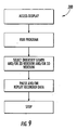
- FIGURE 9 a second program is required to play back previously recorded information as described above with respect to FIGURE 8 .
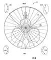
- the saved data from the sensors such as the photodiodes 40a-x can be displayed in a 900 x 900 intensity graph and/or as shown in FIGURE 7 to watch the spread of the simulated biological waste B as measured by changes in humidity, temperature or the photodiode intensity.
- the playback program according to FIGURE 9 can also include the intensity graph to show an X-Y streaming output that changes in amplitude and color intensity as the sensor voltage changes.
- the invention may be better understood with reference to an exemplary operation of the detection and analysis system 10 as described above.
- the mannequin 18 is connected to the controller 20 and to the computer 14 from within the light box 16.
- the mannequin 18 was left in a static position and signal levels of the photodiodes 40a-x were observed in two situations; i.e., with and without a product U donned.
- the signal level of the photodiodes 40a-x without the product U was approximately 1 V. With the product U donned, the signal levels were approximately an order of magnitude less. This was dependant on the location of the photodiode 40a-x with respect to the product U.
- the photodiodes 40a-x that are at the front waist region of the mannequin are severely attenuated due to the opaque nature of the PUB.material landing zone of the product U.
- the mannequin 18 was run through some simple non-repetitive dynamic motions to see the effects on the photodiodes 40a-x. Once the Dragon Skin ® was put in place on the mannequin 18, there was not immediate movement of the photodiodes 40a-x from the surface of the mannequin 18. Due to the rigidity of the heat shrink on the outside of the photodiode connection wires 45, it was suspected that the dynamics of the mannequin 18 may cause the photodiodes 40a-x and the wires 45 to come out of the surface of the mannequin 18. This may have been remedied due to two reasons.
- the wires 45 were probably molded in curved positions and this would prevent an angular placement of the wire 45 (with respects to the normal of the skin surface 22) to allow for it to be mobile within the mannequin 18.
- the clear skin 22 may act as a barrier that holds the photodiodes 40a-x in place. When placed on the mannequin 18, the skin 22 filled in around the photodiodes 40a-x and into the holes 22a-x of the mannequin 18. This may also help the stability of the photodiodes 40a-x in the mannequin 18.
- the photodiode mannequin 18 When donned with the product U and insulted with 60 mL of 10-3 simulant, the photodiode mannequin 18 clearly indicated the presence of a simulated bowel movement (BM) or simulant B when covered.
- BM simulated bowel movement
- simulant B simulant B
- the photodiodes 40a-x are also capable of assessing thickness of the simulant B covering one or more of the photodiodes 40a-x when the simulant B is thin enough and/or translucent to allow some light to pass.
- the edges of clear skin 22 were painted to the top 18A of the torso 18 and down to middle of the legs 18B,C.
- the clear skin 22 was placed into the hole surrounding the insult tube 26 and onto the tube.
- a sized o-ring was then slipped over the tube 26 to hold the skin 22 in place in case peeling occurred.
- the Dragon Skin ® works as a natural buffer for both the mannequin 18 and photodiodes 40a-x. If the skin 22 were to become stained with BM to a point where cleaning becomes problematic or begins to peel in the insult region, the skin can be easily stripped from the mannequin 18 and replaced.
- the original design of the light box 16 incorporated fluorescent lights due to their higher lumen output and temperature regulation. Despite spectral sensitivity data indicating otherwise, the photodiodes 40a-x did not provide an adequate output when exposed to fluorescent lighting. To correct this, the box 16 was retrofitted with incandescent bulbs 32a-x since the spectral sensitivity of the photodiodes 40a-x peaks in the high visible to near infrared region of the electromagnetic spectrum. This retrofit provided sufficient excitation for the photodiodes 40a-x.
- the temperature due to the incandescent bulbs 32a-x varied in the range of 83 to 84 degrees F after one hour of warm up and one hour of monitoring. Therefore, the temperature of the box 16 is acceptable and will create more real conditions (biological temperatures) for testing.
- the technician can rotate the individual photodiode intensity markers 52 about X-Y-Z axes on the display 28 of the computer 14 to present different aspects of the mannequin 18 in order to analyze the spread at particular points on the mannequin 18.
Landscapes
- Engineering & Computer Science (AREA)
- Health & Medical Sciences (AREA)
- Physics & Mathematics (AREA)
- General Physics & Mathematics (AREA)
- Life Sciences & Earth Sciences (AREA)
- Biomedical Technology (AREA)
- Chemical & Material Sciences (AREA)
- Business, Economics & Management (AREA)
- Medicinal Chemistry (AREA)
- General Health & Medical Sciences (AREA)
- Urology & Nephrology (AREA)
- Theoretical Computer Science (AREA)
- Educational Technology (AREA)
- Educational Administration (AREA)
- Computational Mathematics (AREA)
- Molecular Biology (AREA)
- Mathematical Physics (AREA)
- Mathematical Optimization (AREA)
- Mathematical Analysis (AREA)
- Algebra (AREA)
- Medical Informatics (AREA)
- Biophysics (AREA)
- Hematology (AREA)
- Pure & Applied Mathematics (AREA)
- Food Science & Technology (AREA)
- Analytical Chemistry (AREA)
- Biochemistry (AREA)
- Immunology (AREA)
- Pathology (AREA)
- Entrepreneurship & Innovation (AREA)
- Investigating Or Analysing Materials By Optical Means (AREA)
- Investigating Or Analysing Biological Materials (AREA)
Claims (17)
- Système (10) pour analyser des déchets biologiques dans un sous-vêtement, le système (10) comprenant :un mannequin (18) ayant une surface de peau (22) simulée et définissant, au travers de celle-ci, un orifice d'évacuation (26), l'orifice d'évacuation (26) étant configuré pour éliminer un produit d'excrétion humain simulé depuis le mannequin (18), caractérisé parune pluralité de capteurs disposés autour de l'orifice d'évacuation (26), chaque capteur étant configuré pour détecter le produit d'excrétion tandis que le produit d'excrétion est éliminé via l'orifice d'évacuation (26) dans un sous-vêtement disposé autour du mannequin (18) ; etun ordinateur (14) en communication avec les capteurs, l'ordinateur (14) étant configuré pour convertir le produit d'excrétion détecté en un tracé de dispersion défini dans le sous-vêtement ;l'un au moins des capteurs étant une photodiode (40a-x) disposée dans la surface de peau (22) du mannequin (18), la photodiode (40a-x) étant configurée pour détecter une émission de lumière extérieure à la surface de peau (22), la photodiode (40a-x) étant en outre configurée pour signaler à l'ordinateur (14) lorsque le produit d'excrétion affecte l'émission de lumière, la photodiode (40a-x) étant disposée sous un revêtement de polymère transparent, le revêtement de polymère transparent étant disposé sur la surface de peau (22).
- Système (10) tel que défini dans la revendication 1, dans lequel le mannequin (18) est configuré pour simuler des mouvements humains.
- Système (10) tel que défini dans la revendication 1 ou 2, dans lequel la photodiode (40a-x) affleure sensiblement la surface de peau (22).
- Système (10) tel que défini dans l'une quelconque des revendications précédentes, dans lequel l'orifice d'évacuation (26) est sélectionné dans le groupe consistant en un anus simulé, un urètre simulé, et une combinaison des deux.
- Système (10) tel que défini dans la revendication 3 ou 4, dans lequel le produit d'excrétion est d'apparence opaque pour bloquer l'émission lumineuse, ou d'apparence translucide pour modifier l'émission lumineuse.
- Système (10) tel que défini dans l'une quelconque des revendications précédentes, dans lequel le produit d'excrétion est choisi parmi un simulant de fèces et un simulant de menstrues.
- Système (10) tel que défini dans l'une quelconque des revendications 3-6, comprenant, en outre, une source de lumière disposée autour du mannequin (18), la source de lumière étant configurée pour produire l'émission de lumière pour activer la photodiode (40a-x).
- Système (10) tel que défini dans l'une quelconque des revendications précédentes, dans lequel l'un au moins des capteurs est un capteur de chaleur (56a-x) disposé dans le mannequin (18) au moins partiellement exposé à un environnement ambiant, le capteur de chaleur (56a-x) étant configuré pour détecter la présence du produit d'excrétion lorsqu'une température du produit d'excrétion est supérieure à une température ambiante dans l'environnement ambiant, ou l'un au moins des capteurs est un capteur d'humidité (60a-x) disposé dans le mannequin (18), le capteur d'humidité (60a-x) étant configuré pour détecter une humidité du produit d'excrétion.
- Système (10) tel que défini dans l'une quelconque des revendications précédentes, dans lequel l'ordinateur (14) est configuré pour enregistrer le tracé de dispersion en cours de production par le produit d'excrétion en cours de détection par les capteurs.
- Système (10) tel que défini dans la revendication 9, dans lequel l'ordinateur (14) inclut des moyens pour la lecture du tracé de dispersion pour qu'un utilisateur analyse, en temps réel, le tracé de dispersion en cours de formation.
- Système (10) tel que défini dans la revendication 1, 9 ou 10, comprenant, en outre, des moyens de programmation de l'ordinateur (14) pour transformer le produit d'excrétion en le tracé de dispersion, les moyens de programmation incluant, de préférence, un logiciel configuré pour enregistrer le tracé de dispersion en temps réel et pour permettre la lecture du tracé de dispersion pour analyse.
- Système (10) tel que défini dans l'une quelconque des revendications précédentes, comprenant, en outre, un orifice de libération configuré pour libérer de l'urine humaine simulée depuis le mannequin (18) dans le sous-vêtement, l'urine humaine simulée incluant, de préférence, un agent obscurcissant pour affecter la détection par les capteurs.
- Procédé de détermination de la dispersion de déchets biologiques dans un sous-vêtement, le procédé comprenant les étapes de :fourniture d'un mannequin (18), définissant un orifice d'évacuation (26) dudit mannequin, l'orifice d'évacuation (26) étant configuré pour éliminer, depuis le mannequin (18), un produit d'excrétion humain simulé ;caractérisé par les étapes de :disposition d'une pluralité de capteurs autour de l'orifice d'évacuation (26), chaque capteur étant configuré pour détecter le produit d'excrétion tandis que le produit d'excrétion est éliminé via l'orifice d'évacuation (26) dans le sous-vêtement disposé autour du mannequin (18), l'un au moins des capteurs étant une photodiode (40a-x) affleurant sensiblement une surface de peau (22) simulée du mannequin (18) de telle sorte qu'une émission provenant d'une source de lumière est affectée par le produit d'excrétion tandis que le produit d'excrétion se déplace entre la photodiode (40a-x) et la source de lumière, la photodiode (40a-x) étant disposée sous un revêtement transparent, le revêtement transparent étant disposé autour de la surface de peau (22) simulée ; etfourniture d'un ordinateur (14) en communications avec les capteurs, l'ordinateur (14) étant configuré pour convertir le produit d'excrétion détecté en un tracé de dispersion défini dans le sous-vêtement.
- Procédé tel que défini dans la revendication 13, dans lequel les capteurs sont une pluralité de photodiodes (40a-x), une pluralité de capteurs de chaleur (56a-x, une pluralité de capteurs d'humidité (60a-x) ou une combinaison de ceux-ci.
- Procédé tel que défini dans la revendication 13 ou 14, comprenant, en outre, l'étape d'injection d'un agent obscurcissant dans le produit d'excrétion de telle sorte que le produit d'excrétion a une apparence opaque pour bloquer l'émission.
- Procédé tel que défini dans l'une quelconque des revendications 13-15, comprenant, en outre, les étapes d'enregistrement d'un tracé de dispersion du produit d'excrétion en cours de détection par les capteurs et de lecture du tracé de dispersion du produit d'excrétion pour qu'un utilisateur analyse le tracé de dispersion.
- Procédé tel que défini dans l'une quelconque des revendications 13-16, comprenant, en outre, l'étape de mise en mouvement du mannequin (18) tandis que la produit d'excrétion est en cours d'élimination depuis l'orifice d'évacuation (26) dans le sous-vêtement.
Applications Claiming Priority (2)
| Application Number | Priority Date | Filing Date | Title |
|---|---|---|---|
| US11/216,859 US20070048709A1 (en) | 2005-08-31 | 2005-08-31 | System for detection and analysis of biological waste spread in an undergarment |
| PCT/US2006/015289 WO2007027219A1 (fr) | 2005-08-31 | 2006-04-24 | Systeme permettant de detecter et d'analyser des dechets biologiques repandus dans un sous-vetement |
Publications (2)
| Publication Number | Publication Date |
|---|---|
| EP1920232A1 EP1920232A1 (fr) | 2008-05-14 |
| EP1920232B1 true EP1920232B1 (fr) | 2010-04-14 |
Family
ID=36869900
Family Applications (1)
| Application Number | Title | Priority Date | Filing Date |
|---|---|---|---|
| EP06758508A Expired - Lifetime EP1920232B1 (fr) | 2005-08-31 | 2006-04-24 | Systeme permettant de detecter et d'analyser des dechets biologiques repandus dans un sous-vetement |
Country Status (4)
| Country | Link |
|---|---|
| US (1) | US20070048709A1 (fr) |
| EP (1) | EP1920232B1 (fr) |
| DE (1) | DE602006013653D1 (fr) |
| WO (1) | WO2007027219A1 (fr) |
Cited By (4)
| Publication number | Priority date | Publication date | Assignee | Title |
|---|---|---|---|---|
| US10064767B2 (en) | 2012-08-01 | 2018-09-04 | The Procter & Gamble Company | Diaper structure with enhanced tactile softness attributes and providing relatively low humidity |
| US10195092B2 (en) | 2014-03-06 | 2019-02-05 | The Procter & Gamble Company | Multi-component topsheets |
| US10206826B2 (en) | 2014-03-06 | 2019-02-19 | The Procter & Gamble Company | Three-dimensional substrates |
| US10285874B2 (en) | 2014-03-06 | 2019-05-14 | The Procter & Gamble Company | Multi-component topsheets |
Families Citing this family (24)
| Publication number | Priority date | Publication date | Assignee | Title |
|---|---|---|---|---|
| US7566222B2 (en) * | 2004-11-12 | 2009-07-28 | First Quality Retail Services, Llc | Method, apparatus and kit for demonstrating the use of absorbent products |
| US8737704B2 (en) | 2006-08-08 | 2014-05-27 | The Procter And Gamble Company | Methods for analyzing absorbent articles |
| US20090043272A1 (en) * | 2007-08-08 | 2009-02-12 | Tyco Healthcare Retail Services Ag | Training pant article and method for manufacturing |
| US8274393B2 (en) | 2008-12-31 | 2012-09-25 | Kimberly-Clark Worldwide, Inc. | Remote detection systems for absorbent articles |
| US8866624B2 (en) * | 2008-12-31 | 2014-10-21 | Kimberly-Clark Worldwide, Inc. | Conductor-less detection system for an absorbent article |
| US8266956B2 (en) * | 2009-06-10 | 2012-09-18 | The Procter & Gamble Company | Process for demonstrating tissue product break-through |
| US8156821B2 (en) * | 2009-06-10 | 2012-04-17 | The Procter & Gamble Company | Apparatus for determining tissue product break-through |
| US8127601B2 (en) * | 2009-06-10 | 2012-03-06 | The Procter & Gamble Company | Process for determining tissue product break-through |
| DE102009054097A1 (de) * | 2009-11-12 | 2011-05-19 | Paul Hartmann Aktiengesellschaft | Verfahren zum Bestimmen der Feuchtigkeit bei einem absorbierenden Hygienartikel und Vorrichtung zur Durchführung des Verfahrens |
| US8698641B2 (en) | 2010-11-02 | 2014-04-15 | Kimberly-Clark Worldwide, Inc. | Body fluid discriminating sensor |
| CN102800230A (zh) * | 2011-05-24 | 2012-11-28 | 天津市天堰医教科技开发有限公司 | 一种检测女性尿道消毒位置的方法 |
| US9244022B2 (en) | 2011-06-16 | 2016-01-26 | The Procter & Gamble Company | Mannequins for use in imaging and systems including the same |
| US20130052624A1 (en) * | 2011-08-25 | 2013-02-28 | Miguel Saps | Tridimensional stool assessment instrument, methods, and uses thereof |
| US8933292B2 (en) | 2011-10-28 | 2015-01-13 | Kimberly-Clark Worldwide, Inc. | Absorbent article with sensor array for body exudate detection |
| US9119748B2 (en) | 2011-10-28 | 2015-09-01 | Kimberly-Clark Worldwide, Inc. | Electronic discriminating device for body exudate detection |
| US8816149B2 (en) | 2011-10-28 | 2014-08-26 | Kimberly-Clark Worldwide, Inc. | System for detection and monitoring of body exudates using a gas emitting substance for use in interactive toilet training |
| JP2013164277A (ja) * | 2012-02-09 | 2013-08-22 | Gunze Ltd | トルソー及びトルソーを用いた評価方法 |
| MX2015001212A (es) | 2012-08-01 | 2015-04-10 | Procter & Gamble | Estructura de pañal con atributos de suavidad tactil mejorados. |
| CA2976512A1 (fr) | 2015-02-27 | 2016-09-01 | Kimberly-Clark Worldwide, Inc. | Systeme d'evaluation des fuites d'un article absorbant |
| WO2017034796A1 (fr) | 2015-08-26 | 2017-03-02 | The Procter & Gamble Company | Articles absorbants comprenant des substrats tridimensionnels et un repère |
| JP6759369B2 (ja) | 2016-07-01 | 2020-09-23 | ザ プロクター アンド ギャンブル カンパニーThe Procter & Gamble Company | 改善されたトップシート乾燥度を有する吸収性物品 |
| WO2018186842A1 (fr) | 2017-04-05 | 2018-10-11 | Kimberly-Clark Worldwide, Inc. | Vêtement pour détecter des fuites d'un article absorbant et procédés de détection des fuites d'un article absorbant l'utilisant |
| GB2591114B (en) * | 2020-01-16 | 2023-10-25 | Limbs & Things Ltd | Fluid simulation apparatus |
| CN111579562A (zh) * | 2020-05-16 | 2020-08-25 | 台州市椒江芝雅服饰有限公司 | 一种具有内照明灯体的袜子检测器具 |
Family Cites Families (37)
| Publication number | Priority date | Publication date | Assignee | Title |
|---|---|---|---|---|
| US1561285A (en) * | 1920-01-20 | 1925-11-10 | Westinghouse Electric & Mfg Co | Apparatus for testing the rate of liquid absorption by fabrics or the like |
| US2545281A (en) * | 1948-10-19 | 1951-03-13 | Inst Textile Tech | Fabric moisture absorbency tester |
| US3502763A (en) * | 1962-02-03 | 1970-03-24 | Freudenberg Carl Kg | Process of producing non-woven fabric fleece |
| US3502538A (en) * | 1964-08-17 | 1970-03-24 | Du Pont | Bonded nonwoven sheets with a defined distribution of bond strengths |
| US3341394A (en) * | 1966-12-21 | 1967-09-12 | Du Pont | Sheets of randomly distributed continuous filaments |
| US3542615A (en) * | 1967-06-16 | 1970-11-24 | Monsanto Co | Process for producing a nylon non-woven fabric |
| NL6713062A (fr) * | 1967-09-25 | 1969-03-27 | ||
| GB1453447A (en) * | 1972-09-06 | 1976-10-20 | Kimberly Clark Co | Nonwoven thermoplastic fabric |
| US3952584A (en) * | 1975-03-04 | 1976-04-27 | Lichstein Bernard M | Measurement of absorbency characteristics of absorbent structures |
| DE2900690A1 (de) * | 1979-01-10 | 1980-07-24 | Bosch Gmbh Robert | Einrichtung zur temperatursteuerung eines messzwecken dienenden widerstandes, insbesondere bei brennkraftmaschinen |
| US4257188A (en) * | 1979-01-30 | 1981-03-24 | Cpg Products Corp. | Toy dolls and figurines having surface portions of reversibly changeable color |
| US4340563A (en) * | 1980-05-05 | 1982-07-20 | Kimberly-Clark Corporation | Method for forming nonwoven webs |
| US4423471A (en) * | 1982-09-15 | 1983-12-27 | Mycro-Group Company | Mobile lighting fixture, method and boom |
| US4720415A (en) * | 1985-07-30 | 1988-01-19 | Kimberly-Clark Corporation | Composite elastomeric material and process for making the same |
| US4932919A (en) * | 1989-03-13 | 1990-06-12 | Mattel, Inc. | Posable figure with continuous skin |
| US5066259A (en) * | 1990-05-17 | 1991-11-19 | Acker Judith S | Doll structure incorporating material simulating natural body weight and feel |
| US5067924A (en) * | 1990-10-10 | 1991-11-26 | Munter Beverly L | Doll for simulating weight loss/gain |
| US5419729A (en) * | 1992-02-07 | 1995-05-30 | Gross; Flora G. | Toy, doll or mannequin with dimensionally varible exterior surface |
| US5361627A (en) * | 1992-12-31 | 1994-11-08 | Johnson & Johnson Inc. | Method and apparatus for the measuring the capillary attraction developed at a surface of an absorbent body |
| US5425265A (en) * | 1993-12-20 | 1995-06-20 | Jaisinghani; Rajan A. | Apparatus and method for measuring the capillary pressure distribution of porous materials |
| US5518436A (en) * | 1994-07-11 | 1996-05-21 | Cap Toys Inc. | Toy figure and manifold assembly therefor |
| US5913708A (en) * | 1995-05-26 | 1999-06-22 | Gross; Flora Geane | Toy, doll or mannequin with dimensionally variable exterior surface |
| US6015935A (en) * | 1997-03-27 | 2000-01-18 | The Procter & Gamble Company | Absorbent articles comprising a material having a high vertical wicking capacity |
| DE69730123T2 (de) * | 1997-06-25 | 2005-08-18 | The Procter & Gamble Company, Cincinnati | Bewertungsmethode für wegwerfbare absorbierende Artikel |
| US6107537A (en) * | 1997-09-10 | 2000-08-22 | The Procter & Gamble Company | Disposable absorbent articles providing a skin condition benefit |
| US6152906A (en) * | 1998-08-25 | 2000-11-28 | Kimberly-Clark Worldwide, Inc. | Absorbent article having improved breathability |
| FR2787572B1 (fr) * | 1998-12-17 | 2001-02-02 | Franck Courtray | Dispositif pour la realisation de tests sur des substrats absorbants |
| AR027842A1 (es) * | 1999-08-23 | 2003-04-16 | Kimberly Clark Co | Un articulo absorbente el cual mantiene o mejora la salud de la piel |
| US6534074B2 (en) * | 1999-08-24 | 2003-03-18 | Kimberly-Clark Worldwide, Inc. | Absorbent articles providing skin health benefits |
| US6464537B1 (en) * | 1999-12-29 | 2002-10-15 | Berg Technology, Inc. | High speed card edge connectors |
| US6413142B1 (en) * | 2000-09-02 | 2002-07-02 | Virginia Weastler | Expandable doll or the like |
| US6639665B2 (en) * | 2001-02-09 | 2003-10-28 | Institute For Technology Development | Multispectral imaging system for contaminant detection |
| US6543657B2 (en) * | 2001-03-20 | 2003-04-08 | Hong Kong Polytechnic University | Thermal manikin |
| US6557398B2 (en) * | 2001-03-28 | 2003-05-06 | Sca Hygiene Products Ab | Method and a device for determining the liquid retention of absorbent articles |
| US7174774B2 (en) * | 2002-08-30 | 2007-02-13 | Kimberly-Clark Worldwide, Inc. | Method and apparatus of detecting pooling of fluid in disposable or non-disposable absorbent articles |
| US6904820B2 (en) * | 2002-12-20 | 2005-06-14 | Kimberly-Clark Worldwide, Inc. | Method of using a simulated skin substrate and method for determining material dryness performance |
| US6931951B2 (en) * | 2002-12-20 | 2005-08-23 | Kimberly-Clark Worldwide, Inc. | Mechanical device with simulated skin substrate |
-
2005
- 2005-08-31 US US11/216,859 patent/US20070048709A1/en not_active Abandoned
-
2006
- 2006-04-24 WO PCT/US2006/015289 patent/WO2007027219A1/fr not_active Ceased
- 2006-04-24 DE DE602006013653T patent/DE602006013653D1/de not_active Expired - Lifetime
- 2006-04-24 EP EP06758508A patent/EP1920232B1/fr not_active Expired - Lifetime
Cited By (4)
| Publication number | Priority date | Publication date | Assignee | Title |
|---|---|---|---|---|
| US10064767B2 (en) | 2012-08-01 | 2018-09-04 | The Procter & Gamble Company | Diaper structure with enhanced tactile softness attributes and providing relatively low humidity |
| US10195092B2 (en) | 2014-03-06 | 2019-02-05 | The Procter & Gamble Company | Multi-component topsheets |
| US10206826B2 (en) | 2014-03-06 | 2019-02-19 | The Procter & Gamble Company | Three-dimensional substrates |
| US10285874B2 (en) | 2014-03-06 | 2019-05-14 | The Procter & Gamble Company | Multi-component topsheets |
Also Published As
| Publication number | Publication date |
|---|---|
| DE602006013653D1 (de) | 2010-05-27 |
| US20070048709A1 (en) | 2007-03-01 |
| WO2007027219A1 (fr) | 2007-03-08 |
| EP1920232A1 (fr) | 2008-05-14 |
Similar Documents
| Publication | Publication Date | Title |
|---|---|---|
| US20070048709A1 (en) | System for detection and analysis of biological waste spread in an undergarment | |
| Lun et al. | Real-time surface shape sensing for soft and flexible structures using fiber Bragg gratings | |
| JP2019519294A (ja) | 異常を識別するための皮膚検査装置 | |
| US8154534B2 (en) | Detection of an incident light distribution | |
| CN207217073U (zh) | 电子设备和彩色环境光传感器电路 | |
| US20080241952A1 (en) | Sensor with Holographic Multiplexed Image Display | |
| EP2217934B1 (fr) | Ensemble capteur | |
| JPH05509163A (ja) | ポータブル血液分析計器の品質確認のための電気化学センサ信号をシュミレートするための再使用可能なテストユニット | |
| ATE319080T1 (de) | Verwendung eines räumlich-zeitlichen reaktionsverhaltens in sensor-arrays zur detektion von analyten in fluiden | |
| WO1992020273A3 (fr) | Mesure de l'etat metabolique avec hemoglobinometres | |
| CN106415221A (zh) | 紫外光感测 | |
| Carvalho et al. | Smart fingertip sensor for food quality control: Fruit maturity assessment with a magnetic device | |
| JPS6058576A (ja) | オプトエレクトロニツク位置センシング方法およびその装置 | |
| CN104161498B (zh) | 一种体温计 | |
| Arathy et al. | High reliability thermistor probes for early detection of breast cancer using skin contact thermometry with thermal imaging | |
| Panahi et al. | Condition monitoring system: a flexible hybrid electronics approach for sealed container applications | |
| Seesaard et al. | On-cloth wearable E-nose for monitoring and discrimination of body odor signature | |
| Bera et al. | A LabVIEW based data acquisition system for electrical impedance tomography (EIT) | |
| JP4157231B2 (ja) | 放射源可視化装置及び放射源シールド装置 | |
| CN115357136A (zh) | 一种触觉传感器、图像处理方法及图像处理系统 | |
| Gagniuc et al. | Photon-pixel coupling: A method for parallel acquisition of electrical signals in scientific investigations | |
| Compton | Development and characterization of an electrical contact method of measuring body and skin contact with wearable systems | |
| KR102841809B1 (ko) | 전자카드 개별부품에 대한 근접 열화상 취득 시스템 | |
| Rosenberger et al. | A multiplexed optical micro-impedance biosensor array for quantitaitive cancer drug assays | |
| US20240172989A1 (en) | Non-invasive medical examination using electric fields |
Legal Events
| Date | Code | Title | Description |
|---|---|---|---|
| PUAI | Public reference made under article 153(3) epc to a published international application that has entered the european phase |
Free format text: ORIGINAL CODE: 0009012 |
|
| 17P | Request for examination filed |
Effective date: 20080207 |
|
| AK | Designated contracting states |
Kind code of ref document: A1 Designated state(s): DE FR GB |
|
| 17Q | First examination report despatched |
Effective date: 20080624 |
|
| RBV | Designated contracting states (corrected) |
Designated state(s): DE FR GB |
|
| DAX | Request for extension of the european patent (deleted) | ||
| GRAP | Despatch of communication of intention to grant a patent |
Free format text: ORIGINAL CODE: EPIDOSNIGR1 |
|
| GRAS | Grant fee paid |
Free format text: ORIGINAL CODE: EPIDOSNIGR3 |
|
| GRAA | (expected) grant |
Free format text: ORIGINAL CODE: 0009210 |
|
| AK | Designated contracting states |
Kind code of ref document: B1 Designated state(s): DE FR GB |
|
| REG | Reference to a national code |
Ref country code: GB Ref legal event code: FG4D |
|
| REF | Corresponds to: |
Ref document number: 602006013653 Country of ref document: DE Date of ref document: 20100527 Kind code of ref document: P |
|
| PLBE | No opposition filed within time limit |
Free format text: ORIGINAL CODE: 0009261 |
|
| STAA | Information on the status of an ep patent application or granted ep patent |
Free format text: STATUS: NO OPPOSITION FILED WITHIN TIME LIMIT |
|
| 26N | No opposition filed |
Effective date: 20110117 |
|
| PGFP | Annual fee paid to national office [announced via postgrant information from national office to epo] |
Ref country code: FR Payment date: 20110504 Year of fee payment: 6 Ref country code: DE Payment date: 20110427 Year of fee payment: 6 |
|
| PGFP | Annual fee paid to national office [announced via postgrant information from national office to epo] |
Ref country code: GB Payment date: 20110426 Year of fee payment: 6 |
|
| GBPC | Gb: european patent ceased through non-payment of renewal fee |
Effective date: 20120424 |
|
| REG | Reference to a national code |
Ref country code: FR Ref legal event code: ST Effective date: 20121228 |
|
| PG25 | Lapsed in a contracting state [announced via postgrant information from national office to epo] |
Ref country code: GB Free format text: LAPSE BECAUSE OF NON-PAYMENT OF DUE FEES Effective date: 20120424 |
|
| REG | Reference to a national code |
Ref country code: DE Ref legal event code: R119 Ref document number: 602006013653 Country of ref document: DE Effective date: 20121101 |
|
| PG25 | Lapsed in a contracting state [announced via postgrant information from national office to epo] |
Ref country code: FR Free format text: LAPSE BECAUSE OF NON-PAYMENT OF DUE FEES Effective date: 20120430 |
|
| PG25 | Lapsed in a contracting state [announced via postgrant information from national office to epo] |
Ref country code: DE Free format text: LAPSE BECAUSE OF NON-PAYMENT OF DUE FEES Effective date: 20121101 |