EP1920187B2 - Système de lampe frontale à diodes led - Google Patents
Système de lampe frontale à diodes led Download PDFInfo
- Publication number
- EP1920187B2 EP1920187B2 EP06789927.8A EP06789927A EP1920187B2 EP 1920187 B2 EP1920187 B2 EP 1920187B2 EP 06789927 A EP06789927 A EP 06789927A EP 1920187 B2 EP1920187 B2 EP 1920187B2
- Authority
- EP
- European Patent Office
- Prior art keywords
- solid
- light source
- state light
- light guide
- output window
- Prior art date
- Legal status (The legal status is an assumption and is not a legal conclusion. Google has not performed a legal analysis and makes no representation as to the accuracy of the status listed.)
- Expired - Fee Related
Links
Images

Classifications
-
- F—MECHANICAL ENGINEERING; LIGHTING; HEATING; WEAPONS; BLASTING
- F21—LIGHTING
- F21S—NON-PORTABLE LIGHTING DEVICES; SYSTEMS THEREOF; VEHICLE LIGHTING DEVICES SPECIALLY ADAPTED FOR VEHICLE EXTERIORS
- F21S41/00—Illuminating devices specially adapted for vehicle exteriors, e.g. headlamps
- F21S41/20—Illuminating devices specially adapted for vehicle exteriors, e.g. headlamps characterised by refractors, transparent cover plates, light guides or filters
- F21S41/24—Light guides
-
- F—MECHANICAL ENGINEERING; LIGHTING; HEATING; WEAPONS; BLASTING
- F21—LIGHTING
- F21S—NON-PORTABLE LIGHTING DEVICES; SYSTEMS THEREOF; VEHICLE LIGHTING DEVICES SPECIALLY ADAPTED FOR VEHICLE EXTERIORS
- F21S8/00—Lighting devices intended for fixed installation
-
- F—MECHANICAL ENGINEERING; LIGHTING; HEATING; WEAPONS; BLASTING
- F21—LIGHTING
- F21S—NON-PORTABLE LIGHTING DEVICES; SYSTEMS THEREOF; VEHICLE LIGHTING DEVICES SPECIALLY ADAPTED FOR VEHICLE EXTERIORS
- F21S41/00—Illuminating devices specially adapted for vehicle exteriors, e.g. headlamps
- F21S41/10—Illuminating devices specially adapted for vehicle exteriors, e.g. headlamps characterised by the light source
- F21S41/14—Illuminating devices specially adapted for vehicle exteriors, e.g. headlamps characterised by the light source characterised by the type of light source
- F21S41/141—Light emitting diodes [LED]
- F21S41/143—Light emitting diodes [LED] the main emission direction of the LED being parallel to the optical axis of the illuminating device
-
- F—MECHANICAL ENGINEERING; LIGHTING; HEATING; WEAPONS; BLASTING
- F21—LIGHTING
- F21S—NON-PORTABLE LIGHTING DEVICES; SYSTEMS THEREOF; VEHICLE LIGHTING DEVICES SPECIALLY ADAPTED FOR VEHICLE EXTERIORS
- F21S45/00—Arrangements within vehicle lighting devices specially adapted for vehicle exteriors, for purposes other than emission or distribution of light
- F21S45/40—Cooling of lighting devices
- F21S45/47—Passive cooling, e.g. using fins, thermal conductive elements or openings
- F21S45/48—Passive cooling, e.g. using fins, thermal conductive elements or openings with means for conducting heat from the inside to the outside of the lighting devices, e.g. with fins on the outer surface of the lighting device
-
- F—MECHANICAL ENGINEERING; LIGHTING; HEATING; WEAPONS; BLASTING
- F21—LIGHTING
- F21V—FUNCTIONAL FEATURES OR DETAILS OF LIGHTING DEVICES OR SYSTEMS THEREOF; STRUCTURAL COMBINATIONS OF LIGHTING DEVICES WITH OTHER ARTICLES, NOT OTHERWISE PROVIDED FOR
- F21V29/00—Protecting lighting devices from thermal damage; Cooling or heating arrangements specially adapted for lighting devices or systems
- F21V29/50—Cooling arrangements
- F21V29/70—Cooling arrangements characterised by passive heat-dissipating elements, e.g. heat-sinks
- F21V29/74—Cooling arrangements characterised by passive heat-dissipating elements, e.g. heat-sinks with fins or blades
-
- F—MECHANICAL ENGINEERING; LIGHTING; HEATING; WEAPONS; BLASTING
- F21—LIGHTING
- F21Y—INDEXING SCHEME ASSOCIATED WITH SUBCLASSES F21K, F21L, F21S and F21V, RELATING TO THE FORM OR THE KIND OF THE LIGHT SOURCES OR OF THE COLOUR OF THE LIGHT EMITTED
- F21Y2115/00—Light-generating elements of semiconductor light sources
- F21Y2115/10—Light-emitting diodes [LED]
Definitions
- This invention relates to light sources and more particularly to solid-state light sources. Still more particularly it relates to solid-state light sources that can be employed in a headlamp to mimic the light distribution pattern of an incandescent light. Still more particularly, it relates to solid-state light sources useable as automotive headlamp lighting.
- LEDs are now being used in a variety of lighting application, both for efficiency and durability.
- One of the most difficult lighting applications is automotive head lighting, and there is a drive to use LEDs in headlamps because of their long life and ruggedness. Good luminance is required, but LED are significantly less luminous than tungsten halogen filaments or arc discharges; therefore, a plurality of LEDs must be used to generate the total number of lumens required. This may be achieved by ganging a plurality of LEDs together, but dispersed light sources are difficult to optically integrate, and forward automotive lighting requires excellent beam direction. There is then a need for an LED headlamp system with sufficient lumens and good beam structure. It is possible to achieve the headlight function by dispersing LEDs over a great area.
- GB 2 365 962 A discloses a solid-state light source comprising a light pipe which may be solid, having side surfaces to direct light from a light receiving end to a light exiting end.
- a solid-state light source that comprises a plurality of LED units arrayed to emit light generally about an axis.
- a light transmissive light guide has a plurality of input widows with each LED unit facing a respective input window. Each window transversely intercepts the axis and receives light from the LED units.
- a common output window is axially aligned with the input windows.
- the light guide has smooth sidewalls extending between the input windows and the output window and a lens is axially aligned with the output window and has a focal point positioned relative to the output window to refract light received from the output window into a preferred beam pattern directed to a field to be illuminated.
- An electrical connector provides power from an external source to energize the LED units, and a housing retains the LED units, light guide, lens and electrical connector in proper relation.
- the light guide comprises supporting legs to position the light guide in position on said housing by flanges that receive bolts, and said light guide is formed to bridge said LED units and is anchored by said supporting legs to the housing.
- the lens is separate from the light guide and is arranged in front of the output window of the light guide.
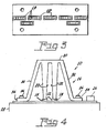
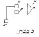
- a solid-state light source 10 comprising a plurality of LED units 12 arrayed to emit light generally about an axis 14.
- Each of the LED units 12 can comprise a number of LEDs, for example, up to five. They may all emit in a single color or multiple colors can be combined for a specific effect.
- a light transmissive light guide 16 is associated with the LED units 12 and has a plurality of input widows 18.
- Each LED unit 12 faces a respective input window 18 and each window 18 transversely intercepts the axis 14 and receives light from the LED units 12.
- the input windows 18 lead to a common output window 20 that is axially aligned with the input windows 18.
- the light guide 16 has smooth sidewalls 22 that extend between the input windows 18 and the output window 20 to enhance total internal reflection in the light guide 16.
- a lens 24 is axially aligned with the output window 20 and has a focal point positioned relative to the output window to refract light received from the output window 20 into a preferred beam pattern directed to a field to be illuminated.
- An electrical connector 26 provides power from an external source to energize the LED units.
- a housing 28 which can also function as a heatsink, retains the LED units 12, the light guide 16, the lens 24 and electrical connector 26 in proper relation.
- a plurality of heat-radiating fins 29 can be provided on the housing 28.
- the output window 20 has an area less than 40 square millimeters.
- a vehicle lamp system 30, shown diagrammatically in Fig. 5 can comprise a plurality of solid-state light sources 10, with different sources being formed to provide different light outputs, for example, on light source 10 can provide a high beam and one can provide a low beam.
- the light sources can be configured to provide beam spread functions, hot spot beam functions, etc.
- the LED units 12 can be contained in ceramic fixtures mounted directly on a printed circuit board.
- the units 12 are preferably arranged in one or two lines, as shown in Figs. 2 and 3 .
- the light guide 16 is formed from a light transmissive material. Glass or plastic, such as polycarbonate may be used. The preferred material is moldable so as to inexpensively take the preferred optical form.
- the light guide has one or more input widows 18 transversely intercepting the beam axis 14 to face the one or more LED units 12 and receive light from the one or more LEDs. In the preferred embodiment, there is one light guide input window 18 for each LED unit 12. If desired, two or more LED units 12 could be directed into a particular input window 18. The preferred individual input windows 18 then span a respective one of the LED unit's output region to capture a substantial part of the emitted light.
- the input window could span all of the LEDs in an array. For example, if five LED units make up the horizontal band of the high beam spread function, the one input window would have a horizontal width slightly greater than five times the LED unit width plus the gap between the adjacent LED units to thereby span the output regions of the five LED units.
- the light guide 16 includes a common output window 20 axially aligned with the input window or windows 18; and spanning the plurality of input windows.
- the common output window 20 in the preferred embodiment, has a greater area than the input window areas, but is still preferably sized to mimic a filament. In general it is desirable to have as small an output window as possible, ultimately creating an ideal optical point source. Unfortunately, a small output window cuts off the amount of light passed, and transmission has to be balanced against optical size.
- the light guide 16 has smooth sidewalls extending between the input window and the output window to enable total internal reflection.
- Supporting legs 32 position the light guide 16 in position on the housing 28 by flanges 34 that receive bolts 36.
- the light guide 16 is formed to bridge the LEDs 12, then be anchored by the legs 32 to the housing 28 so as to securely and accurately fix the input windows 18 adjacent the LEDs 12.
- the light guide with input windows, output window and the support (legs 32) is a unitary body molded from a light transmissive material that is anchored to the substrate supporting the array of LEDs, thereby accurately fixing the input windows in a face to face relation with the respective LEDs.
- the preferred light guide the form of a plurality of tapered portions with their respective narrow input windows 18 facing their respective light supplying LED units 12, while the broader output ends are merged together as a single output window 20.
- the preferred sidewall angle(s) from the respective input windows to the common output window correspond to the beam angle for that particular beam function.
Claims (9)
- Source de lumière (10) à semi-conducteurs comprenant :une pluralité d'unités LED (12) mises en réseau pour émettre de la lumière globalement autour d'un axe (14) ;un guide de lumière (16) à transmission de lumière possédant une pluralité de fenêtres d'entrée (18), chaque unité LED (12) faisant face à une fenêtre d'entrée (18) respective, chaque fenêtre d'entrée (18) interceptant transversalement l'axe (14) et recevant la lumière provenant des unités LED (12) ; et une fenêtre de sortie commune (20) axialement alignée sur les fenêtres d'entrée (18), le guide de lumière (16) comportant des parois latérales lisses s'étendant entre les fenêtres d'entrée (18) et la fenêtre de sortie (20) ;une lentille (24) axialement alignée sur la fenêtre de sortie (20) et possédant un point focal positionné par rapport à la fenêtre de sortie (20) pour réfracter la lumière reçue en provenance de la fenêtre de sortie (20) en un motif de faisceau préféré dirigé vers un champ à éclairer ;un connecteur électrique (26) apportant de l'énergie d'une source externe afin d'alimenter lesdites unités LED (12), etun boîtier (28) pour maintenir les unités LED (12), le guide de lumière (16), la lentille (24) et le connecteur électrique (26) dans une bonne relation,et dans laquelleledit guide de lumière (16) comprend des pattes de support (32) pour positionner le guide de lumière (16) en position sur ledit boîtier (28) par des brides (34) qui reçoivent des boulons (36), et ledit guide de lumière (16) est formé pour enjamber lesdites unités LED (12) et est ancré par lesdites pattes de support (32) au boîtier (28), la lentille (24) étant séparée du guide de lumière (16) etétant disposée devant la fenêtre de sortie (20) du guide de lumière (16).
- Source de lumière à semi-conducteurs selon la revendication 1, dans laquelle ladite fenêtre de sortie (20) a une superficie inférieure à 40 millimètres carrés.
- Source de lumière à semi-conducteurs selon la revendication 1, dans laquelle ledit guide de lumière (16) doté des fenêtres d'entrée (18), de la fenêtre de sortie (20) et des pattes de support (32) est un corps unitaire moulé dans un matériau à transmission de lumière.
- Source de lumière à semi-conducteurs selon l'une des revendications 1 à 3, dans laquelle ladite source de lumière à semi-conducteurs forme une partie d'un système de phare.
- Source de lumière à semi-conducteurs selon la revendication 4, dans laquelle ladite source de lumière à semi-conducteurs a une fonction de faisceau haut.
- Source de lumière à semi-conducteurs selon la revendication 4, dans laquelle ladite source de lumière à semi-conducteurs a une fonction de faisceau bas.
- Source de lumière à semi-conducteurs selon la revendication 4, dans laquelle ladite source de lumière à semi-conducteurs a une fonction de faisceau dispersé.
- Source de lumière à semi-conducteurs selon la revendication 4, dans laquelle ladite source de lumière à semi-conducteurs a une fonction de faisceau à point chaud.
- Source de lumière à semi-conducteurs selon la revendication 4, dans laquelle ladite source de lumière à semi-conducteurs a une fonction de faisceau de pliage.
Applications Claiming Priority (2)
| Application Number | Priority Date | Filing Date | Title |
|---|---|---|---|
| US71277205P | 2005-08-31 | 2005-08-31 | |
| PCT/US2006/032751 WO2007027474A2 (fr) | 2005-08-31 | 2006-08-23 | Système de lampe frontale à diodes led |
Publications (4)
| Publication Number | Publication Date |
|---|---|
| EP1920187A2 EP1920187A2 (fr) | 2008-05-14 |
| EP1920187A4 EP1920187A4 (fr) | 2009-08-19 |
| EP1920187B1 EP1920187B1 (fr) | 2014-11-19 |
| EP1920187B2 true EP1920187B2 (fr) | 2018-09-12 |
Family
ID=37809366
Family Applications (1)
| Application Number | Title | Priority Date | Filing Date |
|---|---|---|---|
| EP06789927.8A Expired - Fee Related EP1920187B2 (fr) | 2005-08-31 | 2006-08-23 | Système de lampe frontale à diodes led |
Country Status (7)
| Country | Link |
|---|---|
| US (1) | US8104939B2 (fr) |
| EP (1) | EP1920187B2 (fr) |
| JP (1) | JP4836209B2 (fr) |
| KR (1) | KR101260910B1 (fr) |
| CN (1) | CN100578076C (fr) |
| TW (1) | TWI422055B (fr) |
| WO (1) | WO2007027474A2 (fr) |
Families Citing this family (30)
| Publication number | Priority date | Publication date | Assignee | Title |
|---|---|---|---|---|
| US7815350B2 (en) | 2005-04-21 | 2010-10-19 | Magna International Inc. | Headlamp with beam patterns formed from semiconductor light sources |
| JP5075385B2 (ja) | 2006-09-28 | 2012-11-21 | 株式会社 資生堂 | 多孔質酸化チタン及びその製造方法 |
| JP5069985B2 (ja) * | 2007-09-13 | 2012-11-07 | 株式会社小糸製作所 | 車両用前照灯の灯具ユニットおよび車両用前照灯 |
| WO2009117834A1 (fr) | 2008-03-26 | 2009-10-01 | Magna International Inc. | Phare antibrouillard et analogue employant des sources de lumière à semi-conducteurs |
| CA2664963A1 (fr) | 2008-05-01 | 2009-11-01 | Magna International Inc. | Dispositif optique en d a coupure de point chaud |
| US8517584B2 (en) | 2008-05-01 | 2013-08-27 | Magna International Inc. | Hotspot cutoff d-optic |
| TWI402788B (zh) * | 2008-05-02 | 2013-07-21 | Hon Hai Prec Ind Co Ltd | 電子裝置 |
| EP2202449A1 (fr) * | 2008-12-23 | 2010-06-30 | Tao Lin | Lumière DEL, en particulier pour une utilisation en tant que feu de croisement et/ou feu de route pour des applications automobiles |
| JP2011108588A (ja) * | 2009-11-20 | 2011-06-02 | Koito Mfg Co Ltd | 発光モジュールおよび車両用灯具 |
| AT510437B1 (de) * | 2011-02-16 | 2012-04-15 | Zizala Lichtsysteme Gmbh | Led-lichtmodul und fahrzeugscheinwerfer |
| CN102182972B (zh) * | 2011-03-28 | 2013-09-25 | 江苏洪昌科技股份有限公司 | 分布式led光纤耦合照明车灯 |
| CN102121654A (zh) * | 2011-03-28 | 2011-07-13 | 江苏洪昌科技股份有限公司 | 光纤耦合半导体激光照明车灯 |
| AT511761B1 (de) * | 2011-08-08 | 2014-02-15 | Zizala Lichtsysteme Gmbh | Led-lichtquellenmodul für einen fahrzeugscheinwerfer sowie fahrzeugscheinwerfer und fahrzeugscheinwerfersystem |
| US8449159B2 (en) | 2011-10-18 | 2013-05-28 | Lawrence M. Rice | Combination optics light emitting diode landing light |
| AT512865B1 (de) * | 2012-05-09 | 2014-12-15 | Zizala Lichtsysteme Gmbh | Beleuchtungseinrichtung für einen Kraftfahrzeugscheinwerfer sowie Lichtmodul und Kraftfahrzeugscheinwerfer mit Beleuchtungseinrichtung |
| DE102013013456B4 (de) | 2012-10-14 | 2023-03-30 | Docter Optics Se | Optisches Element für einen Fahrzeugscheinwerfer |
| US9476557B2 (en) | 2013-01-08 | 2016-10-25 | Ford Global Technologies, Llc | Low profile highly efficient vehicular LED modules and headlamps |
| DE102013207845A1 (de) * | 2013-04-29 | 2014-10-30 | Automotive Lighting Reutlingen Gmbh | Lichtmodul für einen Kraftfahrzeugscheinwerfer |
| DE102014007185B4 (de) * | 2013-06-18 | 2016-02-04 | Docter Optics Se | Optisches Element für einen Fahrzeugscheinwerfer |
| DK178386B1 (en) * | 2013-11-21 | 2016-01-25 | Martin Professional Aps | Illumination system comprising an optical light mixing rod |
| US9243762B1 (en) * | 2013-12-04 | 2016-01-26 | Tony B. Washington | Vehicle safety light device |
| CN103742849B (zh) * | 2013-12-18 | 2016-09-14 | 奇瑞汽车股份有限公司 | 一种基于光导的汽车前照灯及其控制方法 |
| US9103520B1 (en) | 2014-04-18 | 2015-08-11 | Osram Sylvania Inc. | Combination turn and tail multi-color LED lamp |
| US10060592B2 (en) | 2014-07-31 | 2018-08-28 | Ford Global Technologies, Llc | Dual beam pattern vehicular lighting assembly |
| FR3034169B1 (fr) * | 2015-03-23 | 2020-05-29 | Valeo Iluminacion | Module lumineux pour vehicule automobile comprenant deux guides de lumiere et un radiateur comprenant deux faces de montage |
| DE102017117376A1 (de) * | 2017-08-01 | 2019-02-07 | HELLA GmbH & Co. KGaA | Scheinwerfer, insbesondere Scheinwerfer eines Kraftfahrzeugs |
| CN107357002A (zh) * | 2017-08-18 | 2017-11-17 | 嘉兴海拉灯具有限公司 | 一种光导组合及具有该光导组合的车灯 |
| CN107768361B (zh) * | 2017-10-20 | 2023-12-12 | 中山市光圣半导体科技有限责任公司 | 一种高密度紫外光源 |
| DE102019122450A1 (de) * | 2019-08-21 | 2021-02-25 | HELLA GmbH & Co. KGaA | Lichtleitermodul für eine Primäroptikbaugruppe einer Kraftfahrzeugbeleuchtungseinrichtung und Primäroptikbaugruppe |
| US11841120B2 (en) * | 2020-10-06 | 2023-12-12 | Hyundai Motor Company | Light-distributing lens and lighting module using the same |
Citations (9)
| Publication number | Priority date | Publication date | Assignee | Title |
|---|---|---|---|---|
| WO2003048637A1 (fr) † | 2001-12-06 | 2003-06-12 | Fraen Corporation S.R.L. | Module d'eclairage a dissipation elevee de chaleur |
| EP1388461A2 (fr) † | 2002-08-07 | 2004-02-11 | Denso Corporation | Dispositif d'éclairage pour véhicule et procédé pour contrôler la distribution de lumière dudit dispositif |
| WO2004059348A2 (fr) † | 2002-12-16 | 2004-07-15 | 3M Innovative Properties Company | Feuille a reseau de lentilles et procede de moulage |
| WO2004088200A2 (fr) † | 2003-03-31 | 2004-10-14 | Osram Opto Semiconductors Gmbh | Phare et element phare |
| US20040262053A1 (en) † | 2001-10-10 | 2004-12-30 | Bernd Ludewig | Display device |
| EP1630576A2 (fr) † | 2004-08-27 | 2006-03-01 | Osram Opto Semiconductors GmbH | Projecteur avec un faisceau lumineux prédéfini et élément optique primaire pour un projecteur |
| EP1653150A1 (fr) † | 2004-10-21 | 2006-05-03 | Osram Sylvania Inc. | Module de diodes électroluminescentes pour phare de véhicule automobile |
| WO2006045277A2 (fr) † | 2004-10-29 | 2006-05-04 | Osram Opto Semiconductors Gmbh | Dispositif d'eclairage, phares de vehicules automobiles et procede de production d'un dispositif d'eclairage |
| WO2006097067A1 (fr) † | 2005-03-16 | 2006-09-21 | Osram Opto Semiconductors Gmbh | Module emetteur de lumiere equipe de diodes electroluminescentes et de goujons d'assemblage permettant de monter un element optique |
Family Cites Families (14)
| Publication number | Priority date | Publication date | Assignee | Title |
|---|---|---|---|---|
| US5590945A (en) * | 1995-07-26 | 1997-01-07 | Industrial Devices, Inc. | Illuminated line of light using point light source |
| US5895115A (en) * | 1996-01-16 | 1999-04-20 | Lumitex, Inc. | Light emitting panel assemblies for use in automotive applications and the like |
| TW380213B (en) * | 1999-01-21 | 2000-01-21 | Ind Tech Res Inst | Illumination apparatus and image projection apparatus includes the same |
| JP2001118411A (ja) * | 1999-10-20 | 2001-04-27 | Ichikoh Ind Ltd | 車両用灯具 |
| US6527411B1 (en) | 2000-08-01 | 2003-03-04 | Visteon Corporation | Collimating lamp |
| US6443582B1 (en) * | 2000-08-30 | 2002-09-03 | Visteon Corporation | Edge-lit light assembly with light guiding structures |
| ITTO20020103A1 (it) * | 2002-02-06 | 2003-08-06 | Fioravanti Srl | Sistema per l'illuminazione anteriore di un autoveicolo. |
| JP2004103379A (ja) * | 2002-09-09 | 2004-04-02 | Koito Mfg Co Ltd | 車両用標識灯 |
| US6955439B2 (en) * | 2003-02-21 | 2005-10-18 | Guide Corporation | Dual filament static bending lamp |
| US6850095B2 (en) * | 2003-04-25 | 2005-02-01 | Visteon Global Technologies, Inc. | Projector optic assembly |
| EP1738107A4 (fr) * | 2004-04-23 | 2008-12-31 | Light Prescriptions Innovators | Collecteur optique destine a des diodes electroluminescentes |
| US7261452B2 (en) * | 2004-09-22 | 2007-08-28 | Osram Sylvania Inc. | LED headlight |
| US7258474B2 (en) * | 2005-04-21 | 2007-08-21 | Magna International Inc. | Headlamp with beam patterns formed from semiconductor light sources |
| US7815350B2 (en) * | 2005-04-21 | 2010-10-19 | Magna International Inc. | Headlamp with beam patterns formed from semiconductor light sources |
-
2006
- 2006-08-23 EP EP06789927.8A patent/EP1920187B2/fr not_active Expired - Fee Related
- 2006-08-23 CN CN200680031822A patent/CN100578076C/zh not_active Expired - Fee Related
- 2006-08-23 US US11/991,013 patent/US8104939B2/en not_active Expired - Fee Related
- 2006-08-23 WO PCT/US2006/032751 patent/WO2007027474A2/fr active Application Filing
- 2006-08-23 JP JP2008529112A patent/JP4836209B2/ja not_active Expired - Fee Related
- 2006-08-31 TW TW095132100A patent/TWI422055B/zh not_active IP Right Cessation
-
2008
- 2008-03-28 KR KR1020087007587A patent/KR101260910B1/ko active IP Right Grant
Patent Citations (11)
| Publication number | Priority date | Publication date | Assignee | Title |
|---|---|---|---|---|
| US20040262053A1 (en) † | 2001-10-10 | 2004-12-30 | Bernd Ludewig | Display device |
| WO2003048637A1 (fr) † | 2001-12-06 | 2003-06-12 | Fraen Corporation S.R.L. | Module d'eclairage a dissipation elevee de chaleur |
| EP1388461A2 (fr) † | 2002-08-07 | 2004-02-11 | Denso Corporation | Dispositif d'éclairage pour véhicule et procédé pour contrôler la distribution de lumière dudit dispositif |
| WO2004059348A2 (fr) † | 2002-12-16 | 2004-07-15 | 3M Innovative Properties Company | Feuille a reseau de lentilles et procede de moulage |
| WO2004088200A2 (fr) † | 2003-03-31 | 2004-10-14 | Osram Opto Semiconductors Gmbh | Phare et element phare |
| EP1630576A2 (fr) † | 2004-08-27 | 2006-03-01 | Osram Opto Semiconductors GmbH | Projecteur avec un faisceau lumineux prédéfini et élément optique primaire pour un projecteur |
| EP1653150A1 (fr) † | 2004-10-21 | 2006-05-03 | Osram Sylvania Inc. | Module de diodes électroluminescentes pour phare de véhicule automobile |
| WO2006045277A2 (fr) † | 2004-10-29 | 2006-05-04 | Osram Opto Semiconductors Gmbh | Dispositif d'eclairage, phares de vehicules automobiles et procede de production d'un dispositif d'eclairage |
| EP1805815A2 (fr) † | 2004-10-29 | 2007-07-11 | Osram Opto Semiconductors GmbH | Dispositif d'eclairage, phares de vehicules automobiles et procede de production d'un dispositif d'eclairage |
| WO2006097067A1 (fr) † | 2005-03-16 | 2006-09-21 | Osram Opto Semiconductors Gmbh | Module emetteur de lumiere equipe de diodes electroluminescentes et de goujons d'assemblage permettant de monter un element optique |
| EP1859196A1 (fr) † | 2005-03-16 | 2007-11-28 | Osram Opto Semiconductors GmbH | Module emetteur de lumiere equipe de diodes electroluminescentes et de goujons d'assemblage permettant de monter un element optique |
Also Published As
| Publication number | Publication date |
|---|---|
| JP2009506514A (ja) | 2009-02-12 |
| EP1920187B1 (fr) | 2014-11-19 |
| JP4836209B2 (ja) | 2011-12-14 |
| KR20080046689A (ko) | 2008-05-27 |
| EP1920187A4 (fr) | 2009-08-19 |
| EP1920187A2 (fr) | 2008-05-14 |
| WO2007027474A2 (fr) | 2007-03-08 |
| CN100578076C (zh) | 2010-01-06 |
| WO2007027474A3 (fr) | 2007-07-19 |
| US20090213606A1 (en) | 2009-08-27 |
| TW200721546A (en) | 2007-06-01 |
| CN101253364A (zh) | 2008-08-27 |
| TWI422055B (zh) | 2014-01-01 |
| KR101260910B1 (ko) | 2013-05-06 |
| US8104939B2 (en) | 2012-01-31 |
Similar Documents
| Publication | Publication Date | Title |
|---|---|---|
| EP1920187B2 (fr) | Système de lampe frontale à diodes led | |
| US6280480B1 (en) | Indirect illumination taillamp assembly for a vehicle | |
| US20060221613A1 (en) | Virtual point light source | |
| US7237927B2 (en) | Light emitting diode lamp with conically focused light guides | |
| US8007149B2 (en) | Vehicle lighting assembly and light guiding lens for use in vehicle lighting assembly | |
| KR101500759B1 (ko) | 자동차 후방 콤비네이션 램프의 후방 적재된 led 모듈 | |
| US20080062712A1 (en) | Sparsely Spaced Array Led Headlamp | |
| EP1640655A2 (fr) | Ensemble de lampes à diodes électroluminescentes et système réflecteur | |
| US20060181864A1 (en) | Led bulb | |
| JP2009517813A (ja) | 半導体ベースの照明システム、及び自動車用の照明システム用構成部品 | |
| US20100195342A1 (en) | Automotive Signal Light Employing Multi-focal Length Light Pipes | |
| KR20080027874A (ko) | 직접 옵티칼 광가이드 | |
| US7318663B2 (en) | Vehicle with lighting system for tail lights and license plate comprising light emitting diodes and optical waveguide | |
| US20090207610A1 (en) | Combination rear lighting system | |
| GB2393506A (en) | Multiple reflector indirect light source lamp | |
| CA2593294C (fr) | Panneau-guide de lumiere | |
| CN116717743B (zh) | 用于实现功能复用的透镜结构、光学系统及车灯 | |
| KR101571486B1 (ko) | 분할 배광된 대형 광학렌즈 | |
| CN217714789U (zh) | 一种车用新型远光模组 | |
| JP5262611B2 (ja) | レンズ、及び、灯具 | |
| CN113639246A (zh) | 一种前照灯光学组件、照明装置、前照灯和车辆 | |
| JP2020038769A (ja) | 車両用灯具 | |
| KR20160106381A (ko) | 차량용 램프 | |
| KR20160054874A (ko) | 차량용 램프 |
Legal Events
| Date | Code | Title | Description |
|---|---|---|---|
| PUAI | Public reference made under article 153(3) epc to a published international application that has entered the european phase |
Free format text: ORIGINAL CODE: 0009012 |
|
| 17P | Request for examination filed |
Effective date: 20080215 |
|
| AK | Designated contracting states |
Kind code of ref document: A2 Designated state(s): DE FR GB IT SE |
|
| DAX | Request for extension of the european patent (deleted) | ||
| RBV | Designated contracting states (corrected) |
Designated state(s): DE FR GB IT SE |
|
| A4 | Supplementary search report drawn up and despatched |
Effective date: 20090716 |
|
| 17Q | First examination report despatched |
Effective date: 20090910 |
|
| GRAP | Despatch of communication of intention to grant a patent |
Free format text: ORIGINAL CODE: EPIDOSNIGR1 |
|
| INTG | Intention to grant announced |
Effective date: 20140814 |
|
| GRAS | Grant fee paid |
Free format text: ORIGINAL CODE: EPIDOSNIGR3 |
|
| GRAA | (expected) grant |
Free format text: ORIGINAL CODE: 0009210 |
|
| AK | Designated contracting states |
Kind code of ref document: B1 Designated state(s): DE FR GB IT SE |
|
| REG | Reference to a national code |
Ref country code: GB Ref legal event code: FG4D |
|
| REG | Reference to a national code |
Ref country code: DE Ref legal event code: R096 Ref document number: 602006043731 Country of ref document: DE Effective date: 20141231 |
|
| PG25 | Lapsed in a contracting state [announced via postgrant information from national office to epo] |
Ref country code: SE Free format text: LAPSE BECAUSE OF FAILURE TO SUBMIT A TRANSLATION OF THE DESCRIPTION OR TO PAY THE FEE WITHIN THE PRESCRIBED TIME-LIMIT Effective date: 20141119 |
|
| REG | Reference to a national code |
Ref country code: DE Ref legal event code: R026 Ref document number: 602006043731 Country of ref document: DE |
|
| REG | Reference to a national code |
Ref country code: FR Ref legal event code: PLFP Year of fee payment: 10 |
|
| PLBI | Opposition filed |
Free format text: ORIGINAL CODE: 0009260 |
|
| PLAB | Opposition data, opponent's data or that of the opponent's representative modified |
Free format text: ORIGINAL CODE: 0009299OPPO |
|
| 26 | Opposition filed |
Opponent name: VALEO VISION Effective date: 20150819 |
|
| PLAX | Notice of opposition and request to file observation + time limit sent |
Free format text: ORIGINAL CODE: EPIDOSNOBS2 |
|
| R26 | Opposition filed (corrected) |
Opponent name: VALEO VISION Effective date: 20150819 |
|
| PG25 | Lapsed in a contracting state [announced via postgrant information from national office to epo] |
Ref country code: IT Free format text: LAPSE BECAUSE OF FAILURE TO SUBMIT A TRANSLATION OF THE DESCRIPTION OR TO PAY THE FEE WITHIN THE PRESCRIBED TIME-LIMIT Effective date: 20141119 |
|
| PLAF | Information modified related to communication of a notice of opposition and request to file observations + time limit |
Free format text: ORIGINAL CODE: EPIDOSCOBS2 |
|
| PLBB | Reply of patent proprietor to notice(s) of opposition received |
Free format text: ORIGINAL CODE: EPIDOSNOBS3 |
|
| PLAB | Opposition data, opponent's data or that of the opponent's representative modified |
Free format text: ORIGINAL CODE: 0009299OPPO |
|
| REG | Reference to a national code |
Ref country code: FR Ref legal event code: PLFP Year of fee payment: 11 |
|
| R26 | Opposition filed (corrected) |
Opponent name: VALEO VISION Effective date: 20150819 |
|
| PLAB | Opposition data, opponent's data or that of the opponent's representative modified |
Free format text: ORIGINAL CODE: 0009299OPPO |
|
| PLAB | Opposition data, opponent's data or that of the opponent's representative modified |
Free format text: ORIGINAL CODE: 0009299OPPO |
|
| R26 | Opposition filed (corrected) |
Opponent name: VALEO VISION Effective date: 20150819 |
|
| R26 | Opposition filed (corrected) |
Opponent name: VALEO VISION Effective date: 20150819 |
|
| REG | Reference to a national code |
Ref country code: FR Ref legal event code: PLFP Year of fee payment: 12 |
|
| REG | Reference to a national code |
Ref country code: DE Ref legal event code: R079 Ref document number: 602006043731 Country of ref document: DE Free format text: PREVIOUS MAIN CLASS: F21S0008100000 Ipc: F21S0043000000 |
|
| PUAH | Patent maintained in amended form |
Free format text: ORIGINAL CODE: 0009272 |
|
| STAA | Information on the status of an ep patent application or granted ep patent |
Free format text: STATUS: PATENT MAINTAINED AS AMENDED |
|
| REG | Reference to a national code |
Ref country code: FR Ref legal event code: PLFP Year of fee payment: 13 |
|
| 27A | Patent maintained in amended form |
Effective date: 20180912 |
|
| AK | Designated contracting states |
Kind code of ref document: B2 Designated state(s): DE FR GB IT SE |
|
| REG | Reference to a national code |
Ref country code: DE Ref legal event code: R102 Ref document number: 602006043731 Country of ref document: DE |
|
| PGFP | Annual fee paid to national office [announced via postgrant information from national office to epo] |
Ref country code: FR Payment date: 20210819 Year of fee payment: 16 |
|
| PGFP | Annual fee paid to national office [announced via postgrant information from national office to epo] |
Ref country code: GB Payment date: 20210820 Year of fee payment: 16 Ref country code: DE Payment date: 20210819 Year of fee payment: 16 |
|
| REG | Reference to a national code |
Ref country code: DE Ref legal event code: R119 Ref document number: 602006043731 Country of ref document: DE |
|
| GBPC | Gb: european patent ceased through non-payment of renewal fee |
Effective date: 20220823 |
|
| PG25 | Lapsed in a contracting state [announced via postgrant information from national office to epo] |
Ref country code: FR Free format text: LAPSE BECAUSE OF NON-PAYMENT OF DUE FEES Effective date: 20220831 Ref country code: DE Free format text: LAPSE BECAUSE OF NON-PAYMENT OF DUE FEES Effective date: 20230301 |
|
| P01 | Opt-out of the competence of the unified patent court (upc) registered |
Effective date: 20230821 |
|
| PG25 | Lapsed in a contracting state [announced via postgrant information from national office to epo] |
Ref country code: GB Free format text: LAPSE BECAUSE OF NON-PAYMENT OF DUE FEES Effective date: 20220823 |