EP1920100B1 - Actuation device and method - Google Patents
Actuation device and method Download PDFInfo
- Publication number
- EP1920100B1 EP1920100B1 EP06779962A EP06779962A EP1920100B1 EP 1920100 B1 EP1920100 B1 EP 1920100B1 EP 06779962 A EP06779962 A EP 06779962A EP 06779962 A EP06779962 A EP 06779962A EP 1920100 B1 EP1920100 B1 EP 1920100B1
- Authority
- EP
- European Patent Office
- Prior art keywords
- seat
- actuation device
- actuation
- driving member
- floating body
- Prior art date
- Legal status (The legal status is an assumption and is not a legal conclusion. Google has not performed a legal analysis and makes no representation as to the accuracy of the status listed.)
- Active
Links
- 238000000034 method Methods 0.000 title claims description 4
- 238000007667 floating Methods 0.000 claims abstract description 24
- 238000005406 washing Methods 0.000 claims description 32
- 230000009471 action Effects 0.000 claims description 13
- 230000005291 magnetic effect Effects 0.000 claims description 11
- 238000006073 displacement reaction Methods 0.000 claims description 8
- 230000007246 mechanism Effects 0.000 claims description 5
- 230000005484 gravity Effects 0.000 claims description 4
- 239000003599 detergent Substances 0.000 description 21
- 239000003795 chemical substances by application Substances 0.000 description 13
- XLYOFNOQVPJJNP-UHFFFAOYSA-N water Substances O XLYOFNOQVPJJNP-UHFFFAOYSA-N 0.000 description 10
- 230000008878 coupling Effects 0.000 description 5
- 238000010168 coupling process Methods 0.000 description 5
- 238000005859 coupling reaction Methods 0.000 description 5
- 239000000463 material Substances 0.000 description 5
- 230000000694 effects Effects 0.000 description 4
- 239000000654 additive Substances 0.000 description 3
- 239000007788 liquid Substances 0.000 description 3
- 239000012815 thermoplastic material Substances 0.000 description 3
- 230000000996 additive effect Effects 0.000 description 2
- 238000006243 chemical reaction Methods 0.000 description 2
- 230000002093 peripheral effect Effects 0.000 description 2
- 239000004902 Softening Agent Substances 0.000 description 1
- 229910000831 Steel Inorganic materials 0.000 description 1
- 230000005540 biological transmission Effects 0.000 description 1
- 239000007844 bleaching agent Substances 0.000 description 1
- 230000000903 blocking effect Effects 0.000 description 1
- 238000004891 communication Methods 0.000 description 1
- 230000000295 complement effect Effects 0.000 description 1
- 230000006835 compression Effects 0.000 description 1
- 238000007906 compression Methods 0.000 description 1
- 230000005294 ferromagnetic effect Effects 0.000 description 1
- 230000006698 induction Effects 0.000 description 1
- 230000003993 interaction Effects 0.000 description 1
- 238000004519 manufacturing process Methods 0.000 description 1
- 238000000465 moulding Methods 0.000 description 1
- 230000009467 reduction Effects 0.000 description 1
- 230000000284 resting effect Effects 0.000 description 1
- 239000010959 steel Substances 0.000 description 1
- 238000004804 winding Methods 0.000 description 1
Images


Classifications
-
- A—HUMAN NECESSITIES
- A47—FURNITURE; DOMESTIC ARTICLES OR APPLIANCES; COFFEE MILLS; SPICE MILLS; SUCTION CLEANERS IN GENERAL
- A47L—DOMESTIC WASHING OR CLEANING; SUCTION CLEANERS IN GENERAL
- A47L15/00—Washing or rinsing machines for crockery or tableware
- A47L15/42—Details
- A47L15/44—Devices for adding cleaning agents; Devices for dispensing cleaning agents, rinsing aids or deodorants
-
- Y—GENERAL TAGGING OF NEW TECHNOLOGICAL DEVELOPMENTS; GENERAL TAGGING OF CROSS-SECTIONAL TECHNOLOGIES SPANNING OVER SEVERAL SECTIONS OF THE IPC; TECHNICAL SUBJECTS COVERED BY FORMER USPC CROSS-REFERENCE ART COLLECTIONS [XRACs] AND DIGESTS
- Y10—TECHNICAL SUBJECTS COVERED BY FORMER USPC
- Y10T—TECHNICAL SUBJECTS COVERED BY FORMER US CLASSIFICATION
- Y10T74/00—Machine element or mechanism
- Y10T74/20—Control lever and linkage systems
- Y10T74/20012—Multiple controlled elements
Definitions
- the present invention relates to actuation devices having a driving member, a driven member, and actuator means, which can be operated to produce a movement of the driving member; the invention has been developed with particular attention being paid to devices in which the predetermined movement of the driving member is adapted to cause, in a selective way, stokes of different lengths of the driven member.
- Actuation devices of the type referred to above are used in various fields, such as the field of electrical household appliances (e.g. see document WO-A-01/73182 ).
- a dispenser for washing agents which comprises a container, usually configured as drawer, defining a plurality of compartments, provided for containing individual doses of one and the same washing agent, or else of different washing agents (for example, a detergent for carrying out a pre-washing step, a detergent for carrying out a washing step in the strict sense, a rinsing additive or rinse aid, a bleaching agent, etc.).
- the dispenser is configured in such a way that a flow of water is directed, selectively and at appropriate times, to the various compartments of the container so as to remove from an individual compartment the respective dose of washing agent and to carry it into a tank of the machine in order to perform a particular step of the operating program; for this purpose the dispenser typically comprises a movable nozzle, which is displaced linearly or angularly for directing each time the flow of water into the compartment in question of the container, under the control of a programmer device, or timer, of the machine.
- actuation systems designed to produce the movement of the nozzle are generally cumbersome and complicated from the mechanical standpoint in the case where they are provided with just one actuator means, or else costly if they use a plurality of distinct actuators (see, for example, FR-A-2,596,778 and the corresponding discussion of the prior art).
- dispensers designed for supplying detergent and additives at different pre-set times, under the control of the timer of the machine.
- Said dispensers generally comprise a body associated to the front-loading door of the machine, defined in which is a single-dose compartment provided with a lid that is made to open at the appropriate moment of the washing step.
- a tank for the liquid additive associated to which are interception means for control of the corresponding delivery.
- Some of these dispensers have an actuation system comprising a single actuator, provided for operating in all the delivery cycles (see, for example, EP-A-0 602 572 ).
- the systems with just one actuator of a known type used on dishwashers are generally distinguished by rather complicated and cumbersome mechanisms, which comprise a plurality of components that are particularly subject to wear over time.
- the purpose of the present invention is mainly to provide an actuation device of new conception, that is extremely simple from the constructional and functional standpoint and is provided with a mechanism for coupling between the driving member and the driven member that is very compact and not very subject to wear.
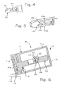
- the reference number 10 designates as a whole an actuation device built according to the invention having a casing 11, which, in the case exemplified, comprises a rear body portion 11a and a front body portion 11b, the latter being represented only partially.
- the casing 11 is adapted to assume an upright, or raised, position and a reclined, or lowered, position; for this purpose, as exemplified schematically in Figure 6 , conveniently associated to the casing 11 are means 13 for hinging to a generic fixed structure, designated by 14; in the sequel of the present description, it is assumed that the structure 14 forms part of a washing machine and that the casing 11 is articulated in relation to the position of a drawer forming part of a dispenser of washing agents, of the type indicated in the introductory part of the present description; the articulation and hinging system is such that, in the condition where the drawer is closed, the casing 11 is in its upright position (represented partially, for example, in Figures 8 , 11 , 14 and 17 ), whereas, with the drawer open, the casing 11 is in its reclined position (as may be seen in Figure 6 ); it may be noted that, in this embodiment of the invention, both in the upright position and in the reclined position, the casing 11 remains in any
- an actuator Positioned in the casing 11 is an actuator, designated as a whole by 20; in the case exemplified, the actuator 20 is of the solenoid type, well known in the field and hence such as not to require any detailed description; here it is sufficient to point out that:
- the movable core 23 has a respective end that projects constantly from the coil 21 and is operatively constrained to a driving member; in the case exemplified, said member is constituted by an angularly movable lever, designated as a whole by 30; the lever 30 defines, in its bottom part, a pin-like portion 30a, used for hinging the lever itself to the casing 11. It may be noted that, according to a possible variant, instead of integrating a pin-like portion 30a, the lever 30 could be fitted to an angularly movable shaft.
- the lever 30 is operatively constrained, in an intermediate area thereof, to a driven member; in the case exemplified, said member is constituted by a shaft or slider or rod 40, which is able to slide linearly in a direction parallel to the movable core 23, i.e., in the direction indicated by the arrow F1.
- the arrangement is such that, following upon supply of the coil 21, with the consequent recession of the movable core in the direction indicated by the arrow F1, the lever 30 is able to move angularly in the direction indicated by the arrow F2, countering the elastic reaction of a spring 15, in particular of the torsion type, interacting between the lever itself and the casing 11.
- an engagement slot or seat 32 made in an intermediate area of the lever 30 is an engagement slot or seat 32, designed to receive a shaped end of the movable core 23 (see, for example, Figure 7 ).
- the lever 30 On top of the slot 32, the lever 30 then has a rectilinear region of reduced thickness, set transverse with respect to the axis of the lever 30, having a plane wall or surface 33; defined in said region is a shaped slot, which provides a seat designated as a whole by 34, open in a position corresponding to the aforesaid plane surface 33; moreover projecting from the plane surface 33 is an engagement part, here configured as appendage or relief 35.
- the seat 34 has a bottom surface 34a and a peripheral profile in which there may be identified an upper surface (not indicated), two longitudinal end surfaces 34b, 34c and a lower surface, the latter being shaped so as to define a substantially plane portion, designated by 34d, and a portion shaped like an inclined plane, designated by 34e, a cusp 34f being formed between said portions.
- the relief 35 has a lateral surface substantially in common with the longitudinal end surface 34c of the seat 34.
- the end of the rod 40 opposite to the actuator 20 comes out of the casing 11, via a passage defined in a side wall 16 of the casing itself; said end of the rod 40 is designed to actuate or move a generic interlocked member or system (not represented in the figures), which here is assumed as being a transmission rod connected to a nozzle provided for directing selectively a flow of water towards the compartments of the aforesaid drawer of the dispenser for washing agents.
- the rod 40 passes also through a second opening, formed in an internal wall 17 of the casing 11.
- the rod 40 has a flange-shaped contrast element 40a, in the area comprised between the walls 16 and 17, and mounted on the rod itself is a spiral spring 18, designed to be loaded in compression; one end of the spring 18 bears upon the wall 17, whilst the other end bears upon the contrast element 40a of the rod 40.
- the end of the rod 40 close to the actuator 20, represented in Figure 4 has a region of reduced cross section, defined in which is a substantially plane surface 43; formed in said region is a shaped slot, which provides a seat designated as a whole by 44, open in a position corresponding to the aforesaid plane surface 43; the seat 44 has a slightly arched longitudinal development and dimensions such as to be able to receive, with possibility of movement, the projecting portion 35 of the lever 30, as will emerge hereinafter.
- the seat 44 has a bottom surface 44a and a peripheral profile in which it is possible to identify an upper surface (not indicated), two longitudinal end surfaces 44b, 44c, and a lower surface; the latter has a profile shaped so as to define a prevalent portion, designated by 44d, and a slide portion 44e, close to the longitudinal end surface 44b; as may be noted, the surface portion 44e is inclined in a direction transverse with respect to the development of the surface portion 44d, providing, that is, a sort of slide, which is lateral with respect to the latter.
- the seat 44, or at least said prevalent surface portion 44d is inclined with respect to the axis of the rod 40.
- the lever 30 and the rod 40 can be conveniently made of thermoplastic material, via moulding operations.
- the reference number 50 designates a floating body, of dimensions such as to be containable both in the seat 34 and in the seat 44, with possibility of displacing selectively between the seats themselves, which are provided for the purpose, as will appear hereinafter; by the term “floating” is meant herein that the body 50 is preferably without constraints, or not joined to other parts, it remaining understood that said body 50, as has been said, is housed alternatively in the seats 34 and 44.
- the aforesaid body is constituted by a ball, for example, a steel ball.
- the lever 30 and the rod 40 are assembled in the device 10, they are arranged in such a way that at least part of the respective plane surfaces 33 and 43, and hence at least part of the seats 34, 44, face one another, with the projecting portion 35 of the lever 30 inserted within the seat 44 of the rod 40, and with part of the rod 40 inserted in the region with reduced thickness of the lever 30 in which the surface 33 is formed.
- the surfaces 33 and 43 of the members 30 and 40 must not necessarily be plane, and could possibly be complementary to one another, and hence even of different shapes (for example, one surface with a convex profile which slides on a surface with a concave profile); in general terms, therefore, it is sufficient for the surfaces 33, 43 to be designed to co-operate with one another in sliding relationship.
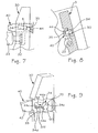
- the actuation device 10 is represented therein in an initial inoperative condition, with the casing 11 in its reclined position, which is obtained when the drawer for the washing agents is opened or pulled out of the respective seat.
- the seats 34 and 44 face one another and are set alongside one another, and the ball 50 is within the seat 34 of the lever 30, and in particular in the lowest stretch of the portion of lower surface 34e, in contact also with the longitudinal end surface 34c. Notwithstanding the inclination of the device 10, and hence of the members 30, 40, the ball 50 is prevented from moving into the seat 44 since, in the condition under examination, the portion of lower surface 44d of the seat 44 is found at a greater height than the portion of lower surface 34e of the seat 34; it should moreover be noted that, in this position, the bottom end of the slide portion 44e of the seat 44 is substantially at the same height as the portion of lower surface 34d of the seat 34.
- the aforesaid nozzle of the dispenser for washing agents will be in a position such as to direct the corresponding flow of water towards a first compartment of the detergent drawer.
- a control system (not represented) controls supply of the coil 21, thus determining recession of the core 23; it should be noted that the supply of the coil determines a fast and sudden movement of the core 23, with a consequent sharp angular movement of the lever 30 as far as the position visible in Figures 10-11 .
- the sharp movement of the lever 30 is such that the ball 50 is induced to climb up the inclined plane defined by the portion of lower surface 34e of the seat 34, until it passes beyond the cusp 34f and then passes to the portion of lower surface 34d, as is clearly visible in Figure 12 ; given the inclination of the device 10, the ball 50 rests laterally with respect to the surface 43 of the rod 40 and is maintained in the position that it has reached thanks to the presence of the cusp 34f.
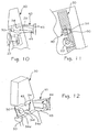
- the electrical supply to the coil 21 is interrupted, with the core 23 and the lever 30 that return to their respective initial positions, thanks to the action of the springs 15 and 18, as represented in Figures 13-15 .
- the ball 50 is free to roll from the portion 34d of the seat 34 onto the slide portion 44e of the seat 44, as may be seen in Figure 15 , and then roll on the portion of lower surface 44d (see Figure 5 ) of the seat 44, until it reaches a position in which it rests against the lateral surface of the relief 35, inserted in said seat.
- the ball 50 passes from the seat 34 to the seat 44; the ball remains in said position thanks to the inclination of the device 10 and to the slightly arched shape of the seat 44.
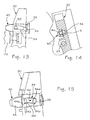
- the control system brings about a new supply of the coil 21, thus bringing about a new recession of the core 23 and hence a new angular movement of the lever 30, as may be seen in Figures 16-18 .
- the respective relief 35 is free to slide within the seat 44 of the rod 40; however, unlike what occurs in the course of the first actuation ( Figures 10-12 ), in this condition the ball 50 is housed within the seat 44, thus reducing the stroke allowed for the relief 35 within the seat 44.
- the relief 35 will displace the ball 50 along the seat 44; at a certain point, as illustrated in Figure 18 , the ball 50 will then come to rest, on one side, against the end surface 44b of the seat 44, and, on the opposite side, a thrust will be exerted on said ball 50 by the relief 35 of the moving lever 30. It is evident how, unlike the previous actuation, a greater part of the angular movement of the lever 30 will in this case be transferred to the rod 40, with a consequent linear translation of the latter. As may be readily understood, the amount of said translation is a function of the overall dimensions of the ball 50. The movement thus obtained of the rod 40 determines the desired actuation.
- Restoring or resetting the initial condition of Figures 7-9 is obtained by bringing the device 10 into its reclined position, as is, for example, visible in Figure 6 , opening the drawer of the washing agents.
- the seats will come to assume a position where they are set on top of one another, in particular with the seat 44 of the rod 40 above the seat 34 of the lever 30, and with the ball 50 that may thus freely pass or fall by gravity from the first seat to the second seat.
- the device 10 will be brought back again into the upright position (see, for example, Figures 8 , 11 , 14 , 17 ) by closing the detergent drawer.
- the embodiment of the invention exemplified previously presupposes, for its operation, a certain degree of inclination of the device 10. It is, however, clear that the device 10 as a whole and/or the members 30, 40 and/or the seats 34, 44 could be configured for enabling the device 10 to operate according to other possible planes of lie, and particularly a plane of lie in which the reclined position of the device is substantially horizontal and the upright position of the device is substantially vertical.
- the simplest way for example, is that of forming or mounting the actuation device 10 and/or the members 30 and 40 with respect to the casing 11 with a slightly inclined configuration, in the direction desired for producing the effects described above.
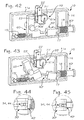
- Another possible embodiment is, instead, exemplified in Figures 22-38 , in which the same numbers as the ones used in the previous figures are partly re-used.
- the device 10 illustrated in Figure 22 is provided with an actuator 20' of a type different from that of the previous embodiment, in particular an electrothermal actuator, or thermo-actuator, well known in the field.
- Said actuator 20' comprises a container body 21' defining a chamber in which a thermally expandable material (such as a wax or a liquid) is present and partially inserted in which is a respective plunger shaft or piston, designated by 23'.
- the actuator 20' then comprises an electrical heater 21 a, for example a positive-temperature-coefficient resistor or PTC, and electrical-supply terminals 22'.
- the heater 21a is supplied via the terminals 22', so as to produce an increase in temperature of the body 21'; in this way, the material contained in the body 21', by being heated, increases in volume and thus pushes the piston 23' outwards; next, when interruption of the electrical supply ceases, the body 21' and the material contained therein cool down progressively, with a consequent reduction in volume of the material itself, and the piston 23' returns towards the inside of the body 21', also under the action of at least one of the elastic elements of the system.
- the actuator 20' could possibly be provided with a respective casing, in which the body 21', the heater 21a and at least part of the terminals 22' will be housed; in a casing of this sort also an actuation shaft, linearly displaceable via the piston 23', would be at least partly inserted.
- the piston 23' of the actuator 20' is designed to produce the angular movement of a lever 60 hinged via a pin 30a'; in the example, the lever 60 is as a whole L-shaped, with a first end portion, upon which the actuator 20' is designed to exert a pushing action, and a second end portion, articulated to which is a driving member, designated by 30', the functions of which, as regards the modalities of interaction with a respective driven member, are similar to the ones of the member 30 of the first embodiment.
- an elastic element such as a spiral spring designated by 15'.
- the lever 60 and the driving member 30' could possibly be made of a single piece, for example, of moulded thermoplastic material, in such a way that the driving member 30' will comprise or will integrate also the lever 60.
- the member 30' has a main body portion, designated by 30a, departing from which is a connection portion 30b, of a reduced cross section.
- the connection portion 30b is articulated, with a certain possibility of relative movement, to an end region of the lever 60; a possible system of articulation between the lever 60 and the member 30' is illustrated schematically in Figure 23 .
- the connection portion 30b is preferably articulated in a flexible or elastic way, in particular by virtue of the characteristics proper to the aforesaid thermoplastic material.
- the aforesaid main body portion 30a is, instead, operatively coupled or constrained to a driven member, which, as in the previous embodiment, is constituted by a rod, shaft or slider, designated by 40'.
- the arrangement of the parts is such that, following upon supply of the thermo-actuator 20', the shaft 23' exerts a thrust on the top area of the lever 60, with the latter that moves angularly in a clockwise direction (as viewed in Figure 22 - see also Figure 40 ), countering the elastic reaction of the spring 18, causing a pulling action on the driving member 30' and a variation of its overall slope with respect to the normal horizontal position.
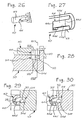
- the portion 30a of the member 30' has a plane face or surface 33', in a position corresponding to which a shaped slot is defined, which provides an as a whole rectilinear seat, designated by 34', open in a position corresponding to the aforesaid plane surface 33'; from the surface 33' there moreover projects an engagement part, also in this case configured as appendage or relief 35'.
- the seat 34' and the relief 35' basically have the same functions as the seat 34 and relief 35 of the first embodiment.
- the seat 34' has a bottom surface 34a', an upper surface, not indicated, two longitudinal end surfaces 34b', 34c' and a lower surface; as may be seen also in Figures 29 and 30 , the lower surface of the seat 34' is shaped so as to define:
- the seat 34' has a depth that increases starting from the end surface 34b' as far as the end surface 34c'; in other words, and as is clearly visible in Figure 28 , the bottom surface 34a' of the seat 34 is as a whole inclined.
- the rod 40' is partially visible in Figure 26 , which also in this example comprises an end region, which has a substantially plane surface 43' and formed in which is a shaped slot, which provides a seat 44', which is open in a position corresponding to the aforesaid plane surface 43' and basically has the same functions as the seat 44 of the first embodiment; the seat 44' has a rectilinear longitudinal development and dimensions such as to be able to receive, with possibility of movement, the projecting portion 35' of the member 30', as is clearly visible in Figures 29 and 30 .
- the seat 44' has a bottom surface 44a', an upper surface, not indicated, two longitudinal end surfaces 44b', 44c' and a lower surface. From Figures 29 and 30 it may be noted how the upper surface and the lower surface of the seat 44' are as a whole inclined in a direction transverse with respect to the development of the seat itself; the lower surface is shaped so as to define a prevalent portion 44d' and a portion 44e' defined hereinafter as "slide portion", at a slightly lower level with respect to the portion 44d' (from the comparison between Figures 29 and 30 it may be noted how the surface portion 44e' and the prevalent portion 44d' have very similar slopes, but lie on different planes).
- a floating element 50 of a spheroidal shape is provided.
- the device 10 it is envisaged for the device 10 to be able to assume a reclined position that is substantially horizontal and an upright position that is substantially vertical.
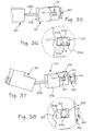
- FIG. 31 and 32 Visible in Figures 31 and 32 is its initial inoperative condition, which precedes a first actuation of the device 10, in which the ball 50 is located within the seat 34 of the lever 30, and in particular in the portion of lower surface 34e'.
- the ball 50 is prevented from displacing within the seat 44' since, in the condition in question, the portion of lower surface 44d' of the seat 44' is at a greater height than the portion of lower surface 34e' of the seat 34'; from Figure 30 it may instead be noted how, in this position, the bottom end of the slide portion 44e' of the seat 44' is substantially at the same height as the portion of lower surface 34d' of the seat 34.
- the control system of the device 10 controls supply of the actuator 20' of Figure 22 , thus determining advance of the piston 23' (see also Figure 40 ), which in turn causes angular movement of the lever 60 as far as the position visible in Figure 33 . It should be noted that, on account of the characteristics proper to thermo-actuators, the movement of the piston 23' is relatively slow, unlike the sharp movement of the core 23 proper to a solenoid actuator.
- the movement of the lever 60 occurs about the pin 30a'; thanks to the articulated coupling existing between the lever 60 and the member 30' (see Figure 23 ), the movement of the lever 60 causes both a pulling action on the member 30' and a certain angular movement thereof; the variation of the overall slope of the member 30' is such that the ball 50 will be able to pass beyond the cusp 34f' of the seat 34' and set itself in the portion of lower surface 34d', as may be seen in Figure 34 .
- the relief 35' is first free to slide within the seat 44', until it reaches a position where it bears upon the end surface 44b' of the seat 44' (see Figure 27 ); from this point on, the further movement of the member 30' is transmitted to the rod 40'.
- the seat 34' also in this case faces a full region of the surface 43' of the rod 40' (see Figure 34 ).
- the ball 50 could reach a position corresponding to the slide portion 44e' even before it has passed beyond the cusp 34f, with the apparent risk that the ball itself may pass, already in this step, onto the slide portion 44e'; in actual fact, however, in the course of the movement, the member 30' is inclined, dropping slightly with respect to the member 40' and thus determining a step between the two seats 34', 44' that is in itself sufficient to prevent the aforesaid risk.
- the surface portion 34d' of the seat 34' could be inclined towards the bottom surface 34a', as mentioned previously, should it be deemed necessary to eliminate also the aforesaid apparent risk.
- the ball 50 passes then from the seat 34' to the seat 44', remaining in the latter seat thanks to the inclination of the lower surface 44d'-44e' of the seat 44; it should be noted that, in effect, the ball 50 remains within the slide portion 44e', given that the latter extends at a height lower with respect to the portion of lower surface 44d' of the seat 44.
- the control system of the device 10 brings about a new supply of the actuator 20', thus causing a new angular movement of the lever 60 and hence a new action of pulling/inclination of the member 30', as may be seen in Figures 37 and 38 .
- the respective relief 35' can slide within the seat 44' of the rod 40', in which the ball 50 is now housed.
- the stroke allowed for the relief 35' within the seat 44' is thus reduced so that, at a certain point - as illustrated in Figure 38 - the ball 50 will be set between the end surface 44b' of the seat 44' and the relief 35' of the moving member 30'.
- the ball 50 remains normally set in a position corresponding to the slide portion 44e', consequently not being subjected to any significant displacements within the seat 44'.
- resetting of the actuation system to the initial condition of Figures 31 and 32 is obtained by bringing first the device 10 into a reclined or substantially horizontal position.
- the seat 44' of the rod 40' comes to occupy a position above the seat 34' of the member 30', with the ball 50 that can thus freely pass from the first seat to the second seat.
- the ball 50 is induced to roll until it comes into contact with the end surface 34c'.
- the ball 50 will remain in the position reached, i.e., within the portion of lower surface 34e' (see, for example, Figure 25 ), without being able to pass into the seat 44' (as has been said - see once again Figure 29 - the portion of lower surface 44d' of the seat 44' is at a greater height than the surface portion 34e' of the seat 34).
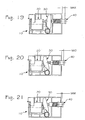
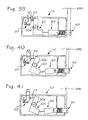
- Figures 39, 40 and 41 the actuation device 10 of the second embodiment of the invention is illustrated schematically in the three conditions represented in Figures 31-32 (or else 35-36), 33-34 and 37-38. Also in this case, it may be readily noted how the end of the driven member 40' will present, in Figures 39-41 , the three different positions MAX, MID and MIN, as described previously also for the first embodiment, in relation to Figures 19-21 . Also the conditions illustrated in Figures 39-41 arise in the course of a washing cycle, with the device 10 in the respective upright position; resetting of the system comes about before starting a new washing cycle on the washing machine, via opening and re-closing of the detergent drawer.
- the actuation device 10 is provided in such a way that the driving member 30, 30' will exert a pulling action on the driven member 40, 40'; the device could in any case be readily conceived for performing an actuation of an opposite type; a case of this sort is represented in Figures 42 and 43 , which the device 10 is pre-arranged in order for the driving member, here designated by 30", to impart a thrust on the driven member, here designated by 40", instead of a pulling action; in this application, hence, the driven member 40 is linearly movable towards the outside of the casing 11.
- the third embodiment illustrated in Figures 42 and 43 is implemented using to a large extent components similar to those of the second embodiment (see, for example, Figure 22 ), with the difference that in this case the actuator 20' is arranged for imparting upon the lever 60 an angular movement in a counterclockwise direction (as viewed in Figures 42, 43 ), and hence for producing both a thrust and a partial raising of the member 30", in the course of the various actuations, as is clearly visible in Figure 43 .
- the device 10 can be used in other contexts.
- the device 10 could be associated to a dispenser for detergents mounted on the door of a top-loaded washing machine, so as to exploit directly the typical movement of the door itself - horizontal when closed and vertical what open - to obtain resetting of the device according to the invention.
- the same may be said for the case of application of the invention on a dispenser of washing agents for a dishwasher, which is usually mounted on the front door of the latter.
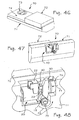
- FIG. 46, 47 and 48 An example of application of this sort is shown in Figures 46, 47 and 48 , where the reference number 70 designates the dispenser, having a main body 71 in the front part of which a compartment for containing the detergent is formed (not visible), functionally associated to which is a respective lid 72; in the case exemplified, the lid 72 is slidably mounted on the body 71 and is able to move between an opening position and a closing position, only the latter being represented in the figures.
- a tank for the liquid rinse aid formed within the body 71 is a tank for the liquid rinse aid, not visible, in communication both with an opening for loading provided with a removable plug, designated by 73, and with a supply opening 74.
- the dispenser 70 is equipped with a hooking/releasing arrangement, provided for blocking the lid 72 in the closing position and then unblocking it, in order to enable it to be opened under the action of elastic means, when the detergent is to be delivered; the dispenser 70 is moreover provided with a valve arrangement, for control of delivery of the rinse aid.
- a hooking/releasing arrangement provided for blocking the lid 72 in the closing position and then unblocking it, in order to enable it to be opened under the action of elastic means, when the detergent is to be delivered
- the dispenser 70 is moreover provided with a valve arrangement, for control of delivery of the rinse aid.
- an actuation device 10 is provided, made substantially according to the first embodiment; from said figures, it may be noted how, for certain applications, the device according to the invention will not necessarily have to comprise a casing, it being sufficient to envisage a supporting structure on which the components of interest are mounted.
- the lever 30 does not present a respective pin-like portion, but is, instead, fitted directly to an end region of a shaft, designated by 75, which forms part of the aforesaid hooking/releasing arrangement of the lid 72; on the other side, the aforesaid valve arrangement for control of delivery of the rinse aid, designated by 76, is instead driven via the rod 40 of the device 10.
- the arrangement is such that, following upon a first actuation of the device 10 (i.e., a condition analogous to that of Figure 20 ), the angular movement of the lever 30 produces rotation of the shaft 75, with consequent opening of the lid 72, and without the limited sliding of the rod 40 causing an actuation of the valve arrangement 76.
- the amount of the movement of the rod 40 will be such as to cause delivery of a dose of rinse aid by the valve arrangement 76.
- resetting of the system will be obtained by exploiting the movement of opening and closing of the door of the dishwasher.
- the device 10 will be conceived in such a way that, following upon first actuation, the movement of the lever 30 will cause a sliding of the rod 40 that is not significant, or not sufficient to cause the desired actuation for the valve arrangement 76.
- the device 10 can in any case be conceived in such a way that, following upon first actuation of the actuator 20, the movement of the lever 30 will not be in effect transferred to the rod 40, i.e., - in general terms - with the driven member 40 that remains substantially motionless; this may be readily obtained by proportioning suitably the seats 34, 44 and the ball 50.
- the device 10 according to the invention is provided for being fixed or mounted in a position such that it remains constantly vertical (second embodiment) or almost vertical (first embodiment), or without variations of its plane of lie.
- a magnetic element in order to cause passage of the ball 50 from the seat 44, 44' to the seat 34, 34', operatively associated to the device 10 is a magnetic element.
- said magnetic element comprises an electromagnet, which can be actuated selectively via a suitable control system (for example, the timer of a washing machine or a dishwasher) in order to produce at the appropriate moment a magnetic field of suitable polarity to attract or else repel the ball 50 into the desired seat, respectively via a phenomenon of magnetic attraction or magnetic repulsion.
- the control system is, in this case, provided for generating the aforesaid magnetic field in the appropriate times and ways, and the ball 50, or the floating body of other form that performs the functions thereof, is made of a suitable material, preferably, of a ferromagnetic type.
- a permanent magnet associated to a component that selectively comes to occupy a position in the vicinity of the device 10, or rather of the area of intersection between the members 30, 30', 30" and 40, 40, 40, 40.
- a permanent magnet of this sort could be associated to the lid 72 of a dishwasher dispenser, in a suitable position in order that, with the lid closed, the magnetic field will affect the area of intersection between the members 30 and 40.
- the system can be conceived in such a way that the magnet will generate a force of attraction or repulsion such as to force the ball 50 into the seat 34; consequently, following upon opening of the lid 72, with consequent moving away of the aforesaid magnetic field from the area of intersection between the members 30 and 40, the ball 50 will be able to pass from the seat 34 to the seat 44, in the ways described above; next, prior to starting of a new washing cycle, closing of the lid 72 will enable the magnetic field to be brought back into the area of interest, in order to cause passage of the ball 50 from the seat 44 to the seat 34, in order to reset the actuation system.
- the invention may, of course, be applied also to fields other than that of electrical household appliances, mentioned herein only by way of example.
Landscapes
- Transmission Devices (AREA)
- Seats For Vehicles (AREA)
Priority Applications (1)
| Application Number | Priority Date | Filing Date | Title |
|---|---|---|---|
| PL06779962T PL1920100T3 (pl) | 2005-08-05 | 2006-08-03 | Urządzenie uruchamiające i sposób |
Applications Claiming Priority (2)
| Application Number | Priority Date | Filing Date | Title |
|---|---|---|---|
| IT000555A ITTO20050555A1 (it) | 2005-08-05 | 2005-08-05 | Dispositivo e metodo di attuazione |
| PCT/IB2006/002202 WO2007017749A1 (en) | 2005-08-05 | 2006-08-03 | Actuation device and method |
Publications (2)
| Publication Number | Publication Date |
|---|---|
| EP1920100A1 EP1920100A1 (en) | 2008-05-14 |
| EP1920100B1 true EP1920100B1 (en) | 2012-06-06 |
Family
ID=37192628
Family Applications (1)
| Application Number | Title | Priority Date | Filing Date |
|---|---|---|---|
| EP06779962A Active EP1920100B1 (en) | 2005-08-05 | 2006-08-03 | Actuation device and method |
Country Status (6)
| Country | Link |
|---|---|
| US (1) | US7823236B2 (es) |
| EP (1) | EP1920100B1 (es) |
| ES (1) | ES2387403T3 (es) |
| IT (1) | ITTO20050555A1 (es) |
| PL (1) | PL1920100T3 (es) |
| WO (1) | WO2007017749A1 (es) |
Families Citing this family (5)
| Publication number | Priority date | Publication date | Assignee | Title |
|---|---|---|---|---|
| ITTO20050554A1 (it) * | 2005-08-05 | 2007-02-06 | Eltek Spa | Dispensatore di agenti di lavaggio per una macchina di lavaggio domestica, in particolare una lavastoviglie |
| ITTO20070597A1 (it) * | 2007-08-09 | 2009-02-10 | Eltek Spa | Dispositivo di attuazione |
| IT1404048B1 (it) * | 2011-02-08 | 2013-11-08 | Bitron Spa | Dispositivo erogatore integrato di agenti di lavaggio per una macchina lavatrice, in particolare una macchina lavastoviglie. |
| US8881748B2 (en) * | 2012-12-18 | 2014-11-11 | Whirlpool Corporation | Dishwasher detergent dispenser |
| CN111394948A (zh) * | 2020-04-01 | 2020-07-10 | 安徽康佳同创电器有限公司 | 一种洗涤剂盒组件及洗衣机 |
Family Cites Families (12)
| Publication number | Priority date | Publication date | Assignee | Title |
|---|---|---|---|---|
| US2759347A (en) * | 1950-12-23 | 1956-08-21 | Gen Motors Corp | Domestic appliance |
| US2729089A (en) * | 1952-02-08 | 1956-01-03 | Eastern Malleable Iron Company | Solenoid-controlled door lock |
| FR2489858A1 (fr) | 1980-09-05 | 1982-03-12 | Esswein Sa | Ensemble distributeur de lessive et distributeur-doseur de produit liquide et machine a laver munie d'un tel ensemble |
| SE452248B (sv) | 1983-01-10 | 1987-11-23 | Aweco Apparate U Geretebau Gmb | Anordning for tillforsel resp dosering av tva rengoringsmedel |
| US4613176A (en) * | 1983-06-29 | 1986-09-23 | Reliable Security Systems, Inc. | Door latch mechanism |
| IT207788Z2 (it) | 1986-04-04 | 1988-02-15 | Eltek Spa | Gruppo deviatore d acqua associabile a programmatori elettronici particolarmente per macchine lavatrici |
| US5271253A (en) * | 1992-03-16 | 1993-12-21 | Mas-Hamilton Group | Electronic combination lock with magnetic anti-attack interlock |
| FR2697543A1 (fr) | 1992-10-30 | 1994-05-06 | Sextant Avionique | Buse orientable pour bacs de produits de lavage. |
| IT1265750B1 (it) | 1992-12-16 | 1996-12-02 | Eltek Spa | Dispositivo dispensatore di sostanze liquide e/o in polvere, in particolare per macchine di lavaggio |
| JP2000137937A (ja) * | 1998-10-30 | 2000-05-16 | Toshiba Corp | ディスク装置 |
| IT1320649B1 (it) * | 2000-03-29 | 2003-12-10 | Eltek Spa | Dispositivo dispensatore di agenti di lavaggio per una macchina dilavaggio domestica, in particolare una lavastoviglie. |
| KR100436497B1 (ko) * | 2002-02-20 | 2004-06-30 | 이중재 | 솔레노이드 잠금장치 |
-
2005
- 2005-08-05 IT IT000555A patent/ITTO20050555A1/it unknown
-
2006
- 2006-08-03 US US11/997,863 patent/US7823236B2/en active Active
- 2006-08-03 EP EP06779962A patent/EP1920100B1/en active Active
- 2006-08-03 PL PL06779962T patent/PL1920100T3/pl unknown
- 2006-08-03 WO PCT/IB2006/002202 patent/WO2007017749A1/en active Application Filing
- 2006-08-03 ES ES06779962T patent/ES2387403T3/es active Active
Also Published As
| Publication number | Publication date |
|---|---|
| EP1920100A1 (en) | 2008-05-14 |
| US20080223166A1 (en) | 2008-09-18 |
| PL1920100T3 (pl) | 2012-11-30 |
| US7823236B2 (en) | 2010-11-02 |
| WO2007017749A8 (en) | 2007-07-19 |
| ITTO20050555A1 (it) | 2007-02-06 |
| ES2387403T3 (es) | 2012-09-21 |
| WO2007017749A1 (en) | 2007-02-15 |
Similar Documents
| Publication | Publication Date | Title |
|---|---|---|
| EP1909632B1 (en) | Washing agent dispenser for a household washing machine, in particular a dishwasher | |
| EP2025982B1 (en) | Actuation device | |
| US6923191B2 (en) | Washing agents dispenser device for a domestic washing machine, namely a dishwasher | |
| EP1920100B1 (en) | Actuation device and method | |
| US7047987B2 (en) | Washing agent dispensing device for a household washing machine, in particular a dishwasher | |
| US7337635B2 (en) | Washing agent dispenser for a domestic washing machine, namely a dishwasher | |
| US7063092B2 (en) | Washing agent dispensing device for a household washing machine, in particular a dishwasher | |
| CA2562601C (en) | An integrated washing agent dispenser, in particular for a dishwasher | |
| JPH04231096A (ja) | 保存された材料および製品の取り出し装置 | |
| EP1450661B1 (en) | Dispenser device particularly for dishwashing machines | |
| EP1379156A1 (en) | Washing agents dispenser device for a dishwashing machine | |
| EP0602572B1 (en) | Dispenser device for liquid and/or powder agents, particularly for washing machines | |
| EP2680736B1 (en) | An integrated device for dispensing washing agents for a washing machine, in particular for a dishwashing machine | |
| EP1455631B1 (en) | A dispenser of washing agents for a household washing machine, in particular a dish-washer | |
| GB2330522A (en) | One-shot detergent dispenser for dishwashers or the like | |
| KR100716002B1 (ko) | 드럼세탁기의 도어잠금장치 | |
| KR20070036468A (ko) | 드럼 세탁기 | |
| EP2478819B1 (en) | A washing agent dispensing device for a washing machine for household use, in particular a dishwasher, and washing machine thereof | |
| EP1245180A2 (en) | Household dishwashing machine with dispenser device for washing agents | |
| EP2101627B1 (en) | A dishwasher | |
| EP0392247A1 (en) | A domestic drying machine for laundry provided with an improved safety device |
Legal Events
| Date | Code | Title | Description |
|---|---|---|---|
| PUAI | Public reference made under article 153(3) epc to a published international application that has entered the european phase |
Free format text: ORIGINAL CODE: 0009012 |
|
| AK | Designated contracting states |
Kind code of ref document: A1 Designated state(s): AT BE BG CH CY CZ DE DK EE ES FI FR GB GR HU IE IS IT LI LT LU LV MC NL PL PT RO SE SI SK TR |
|
| 17P | Request for examination filed |
Effective date: 20080205 |
|
| GRAP | Despatch of communication of intention to grant a patent |
Free format text: ORIGINAL CODE: EPIDOSNIGR1 |
|
| DAX | Request for extension of the european patent (deleted) | ||
| GRAS | Grant fee paid |
Free format text: ORIGINAL CODE: EPIDOSNIGR3 |
|
| GRAA | (expected) grant |
Free format text: ORIGINAL CODE: 0009210 |
|
| AK | Designated contracting states |
Kind code of ref document: B1 Designated state(s): AT BE BG CH CY CZ DE DK EE ES FI FR GB GR HU IE IS IT LI LT LU LV MC NL PL PT RO SE SI SK TR |
|
| REG | Reference to a national code |
Ref country code: GB Ref legal event code: FG4D |
|
| REG | Reference to a national code |
Ref country code: CH Ref legal event code: EP Ref country code: AT Ref legal event code: REF Ref document number: 561107 Country of ref document: AT Kind code of ref document: T Effective date: 20120615 |
|
| REG | Reference to a national code |
Ref country code: IE Ref legal event code: FG4D |
|
| REG | Reference to a national code |
Ref country code: DE Ref legal event code: R096 Ref document number: 602006029976 Country of ref document: DE Effective date: 20120802 |
|
| REG | Reference to a national code |
Ref country code: ES Ref legal event code: FG2A Ref document number: 2387403 Country of ref document: ES Kind code of ref document: T3 Effective date: 20120921 |
|
| REG | Reference to a national code |
Ref country code: NL Ref legal event code: VDEP Effective date: 20120606 |
|
| PG25 | Lapsed in a contracting state [announced via postgrant information from national office to epo] |
Ref country code: CY Free format text: LAPSE BECAUSE OF FAILURE TO SUBMIT A TRANSLATION OF THE DESCRIPTION OR TO PAY THE FEE WITHIN THE PRESCRIBED TIME-LIMIT Effective date: 20120606 Ref country code: SE Free format text: LAPSE BECAUSE OF FAILURE TO SUBMIT A TRANSLATION OF THE DESCRIPTION OR TO PAY THE FEE WITHIN THE PRESCRIBED TIME-LIMIT Effective date: 20120606 Ref country code: FI Free format text: LAPSE BECAUSE OF FAILURE TO SUBMIT A TRANSLATION OF THE DESCRIPTION OR TO PAY THE FEE WITHIN THE PRESCRIBED TIME-LIMIT Effective date: 20120606 Ref country code: LT Free format text: LAPSE BECAUSE OF FAILURE TO SUBMIT A TRANSLATION OF THE DESCRIPTION OR TO PAY THE FEE WITHIN THE PRESCRIBED TIME-LIMIT Effective date: 20120606 |
|
| PGFP | Annual fee paid to national office [announced via postgrant information from national office to epo] |
Ref country code: GB Payment date: 20120801 Year of fee payment: 7 |
|
| REG | Reference to a national code |
Ref country code: AT Ref legal event code: MK05 Ref document number: 561107 Country of ref document: AT Kind code of ref document: T Effective date: 20120606 |
|
| REG | Reference to a national code |
Ref country code: LT Ref legal event code: MG4D Effective date: 20120606 |
|
| PG25 | Lapsed in a contracting state [announced via postgrant information from national office to epo] |
Ref country code: SI Free format text: LAPSE BECAUSE OF FAILURE TO SUBMIT A TRANSLATION OF THE DESCRIPTION OR TO PAY THE FEE WITHIN THE PRESCRIBED TIME-LIMIT Effective date: 20120606 Ref country code: LV Free format text: LAPSE BECAUSE OF FAILURE TO SUBMIT A TRANSLATION OF THE DESCRIPTION OR TO PAY THE FEE WITHIN THE PRESCRIBED TIME-LIMIT Effective date: 20120606 Ref country code: GR Free format text: LAPSE BECAUSE OF FAILURE TO SUBMIT A TRANSLATION OF THE DESCRIPTION OR TO PAY THE FEE WITHIN THE PRESCRIBED TIME-LIMIT Effective date: 20120907 |
|
| REG | Reference to a national code |
Ref country code: PL Ref legal event code: T3 |
|
| PGFP | Annual fee paid to national office [announced via postgrant information from national office to epo] |
Ref country code: ES Payment date: 20120907 Year of fee payment: 7 Ref country code: FR Payment date: 20120823 Year of fee payment: 7 |
|
| PG25 | Lapsed in a contracting state [announced via postgrant information from national office to epo] |
Ref country code: NL Free format text: LAPSE BECAUSE OF FAILURE TO SUBMIT A TRANSLATION OF THE DESCRIPTION OR TO PAY THE FEE WITHIN THE PRESCRIBED TIME-LIMIT Effective date: 20120606 Ref country code: RO Free format text: LAPSE BECAUSE OF FAILURE TO SUBMIT A TRANSLATION OF THE DESCRIPTION OR TO PAY THE FEE WITHIN THE PRESCRIBED TIME-LIMIT Effective date: 20120606 Ref country code: EE Free format text: LAPSE BECAUSE OF FAILURE TO SUBMIT A TRANSLATION OF THE DESCRIPTION OR TO PAY THE FEE WITHIN THE PRESCRIBED TIME-LIMIT Effective date: 20120606 Ref country code: AT Free format text: LAPSE BECAUSE OF FAILURE TO SUBMIT A TRANSLATION OF THE DESCRIPTION OR TO PAY THE FEE WITHIN THE PRESCRIBED TIME-LIMIT Effective date: 20120606 Ref country code: SK Free format text: LAPSE BECAUSE OF FAILURE TO SUBMIT A TRANSLATION OF THE DESCRIPTION OR TO PAY THE FEE WITHIN THE PRESCRIBED TIME-LIMIT Effective date: 20120606 Ref country code: IS Free format text: LAPSE BECAUSE OF FAILURE TO SUBMIT A TRANSLATION OF THE DESCRIPTION OR TO PAY THE FEE WITHIN THE PRESCRIBED TIME-LIMIT Effective date: 20121006 Ref country code: CZ Free format text: LAPSE BECAUSE OF FAILURE TO SUBMIT A TRANSLATION OF THE DESCRIPTION OR TO PAY THE FEE WITHIN THE PRESCRIBED TIME-LIMIT Effective date: 20120606 Ref country code: BE Free format text: LAPSE BECAUSE OF NON-PAYMENT OF DUE FEES Effective date: 20120606 |
|
| PG25 | Lapsed in a contracting state [announced via postgrant information from national office to epo] |
Ref country code: PT Free format text: LAPSE BECAUSE OF FAILURE TO SUBMIT A TRANSLATION OF THE DESCRIPTION OR TO PAY THE FEE WITHIN THE PRESCRIBED TIME-LIMIT Effective date: 20121008 |
|
| REG | Reference to a national code |
Ref country code: CH Ref legal event code: PL |
|
| PG25 | Lapsed in a contracting state [announced via postgrant information from national office to epo] |
Ref country code: MC Free format text: LAPSE BECAUSE OF NON-PAYMENT OF DUE FEES Effective date: 20120831 |
|
| PLBE | No opposition filed within time limit |
Free format text: ORIGINAL CODE: 0009261 |
|
| STAA | Information on the status of an ep patent application or granted ep patent |
Free format text: STATUS: NO OPPOSITION FILED WITHIN TIME LIMIT |
|
| PG25 | Lapsed in a contracting state [announced via postgrant information from national office to epo] |
Ref country code: LI Free format text: LAPSE BECAUSE OF NON-PAYMENT OF DUE FEES Effective date: 20120831 Ref country code: CH Free format text: LAPSE BECAUSE OF NON-PAYMENT OF DUE FEES Effective date: 20120831 Ref country code: DK Free format text: LAPSE BECAUSE OF FAILURE TO SUBMIT A TRANSLATION OF THE DESCRIPTION OR TO PAY THE FEE WITHIN THE PRESCRIBED TIME-LIMIT Effective date: 20120606 |
|
| 26N | No opposition filed |
Effective date: 20130307 |
|
| REG | Reference to a national code |
Ref country code: IE Ref legal event code: MM4A |
|
| REG | Reference to a national code |
Ref country code: DE Ref legal event code: R097 Ref document number: 602006029976 Country of ref document: DE Effective date: 20130307 |
|
| PG25 | Lapsed in a contracting state [announced via postgrant information from national office to epo] |
Ref country code: IE Free format text: LAPSE BECAUSE OF NON-PAYMENT OF DUE FEES Effective date: 20120803 Ref country code: BG Free format text: LAPSE BECAUSE OF FAILURE TO SUBMIT A TRANSLATION OF THE DESCRIPTION OR TO PAY THE FEE WITHIN THE PRESCRIBED TIME-LIMIT Effective date: 20120906 |
|
| GBPC | Gb: european patent ceased through non-payment of renewal fee |
Effective date: 20130803 |
|
| REG | Reference to a national code |
Ref country code: FR Ref legal event code: ST Effective date: 20140430 |
|
| PG25 | Lapsed in a contracting state [announced via postgrant information from national office to epo] |
Ref country code: LU Free format text: LAPSE BECAUSE OF NON-PAYMENT OF DUE FEES Effective date: 20120803 |
|
| PG25 | Lapsed in a contracting state [announced via postgrant information from national office to epo] |
Ref country code: HU Free format text: LAPSE BECAUSE OF FAILURE TO SUBMIT A TRANSLATION OF THE DESCRIPTION OR TO PAY THE FEE WITHIN THE PRESCRIBED TIME-LIMIT Effective date: 20060803 Ref country code: GB Free format text: LAPSE BECAUSE OF NON-PAYMENT OF DUE FEES Effective date: 20130803 |
|
| PG25 | Lapsed in a contracting state [announced via postgrant information from national office to epo] |
Ref country code: FR Free format text: LAPSE BECAUSE OF NON-PAYMENT OF DUE FEES Effective date: 20130902 |
|
| REG | Reference to a national code |
Ref country code: ES Ref legal event code: FD2A Effective date: 20140905 |
|
| PG25 | Lapsed in a contracting state [announced via postgrant information from national office to epo] |
Ref country code: ES Free format text: LAPSE BECAUSE OF NON-PAYMENT OF DUE FEES Effective date: 20130804 |
|
| PGFP | Annual fee paid to national office [announced via postgrant information from national office to epo] |
Ref country code: TR Payment date: 20220714 Year of fee payment: 17 Ref country code: IT Payment date: 20220712 Year of fee payment: 17 Ref country code: DE Payment date: 20220628 Year of fee payment: 17 |
|
| PGFP | Annual fee paid to national office [announced via postgrant information from national office to epo] |
Ref country code: PL Payment date: 20220711 Year of fee payment: 17 |
|
| P01 | Opt-out of the competence of the unified patent court (upc) registered |
Effective date: 20230529 |
|
| REG | Reference to a national code |
Ref country code: DE Ref legal event code: R119 Ref document number: 602006029976 Country of ref document: DE |
|
| PG25 | Lapsed in a contracting state [announced via postgrant information from national office to epo] |
Ref country code: IT Free format text: LAPSE BECAUSE OF NON-PAYMENT OF DUE FEES Effective date: 20230803 Ref country code: DE Free format text: LAPSE BECAUSE OF NON-PAYMENT OF DUE FEES Effective date: 20240301 |