EP1919261A1 - Konstantstromsteuerungseinrichtung auf Niederfrequenz für hochleistungen LED - Google Patents
Konstantstromsteuerungseinrichtung auf Niederfrequenz für hochleistungen LED Download PDFInfo
- Publication number
- EP1919261A1 EP1919261A1 EP06291718A EP06291718A EP1919261A1 EP 1919261 A1 EP1919261 A1 EP 1919261A1 EP 06291718 A EP06291718 A EP 06291718A EP 06291718 A EP06291718 A EP 06291718A EP 1919261 A1 EP1919261 A1 EP 1919261A1
- Authority
- EP
- European Patent Office
- Prior art keywords
- switch
- voltage
- electronic circuit
- input
- comparator
- Prior art date
- Legal status (The legal status is an assumption and is not a legal conclusion. Google has not performed a legal analysis and makes no representation as to the accuracy of the status listed.)
- Withdrawn
Links
Images

Classifications
-
- H—ELECTRICITY
- H05—ELECTRIC TECHNIQUES NOT OTHERWISE PROVIDED FOR
- H05B—ELECTRIC HEATING; ELECTRIC LIGHT SOURCES NOT OTHERWISE PROVIDED FOR; CIRCUIT ARRANGEMENTS FOR ELECTRIC LIGHT SOURCES, IN GENERAL
- H05B45/00—Circuit arrangements for operating light-emitting diodes [LED]
- H05B45/30—Driver circuits
- H05B45/37—Converter circuits
- H05B45/3725—Switched mode power supply [SMPS]
- H05B45/382—Switched mode power supply [SMPS] with galvanic isolation between input and output
-
- H—ELECTRICITY
- H05—ELECTRIC TECHNIQUES NOT OTHERWISE PROVIDED FOR
- H05B—ELECTRIC HEATING; ELECTRIC LIGHT SOURCES NOT OTHERWISE PROVIDED FOR; CIRCUIT ARRANGEMENTS FOR ELECTRIC LIGHT SOURCES, IN GENERAL
- H05B45/00—Circuit arrangements for operating light-emitting diodes [LED]
- H05B45/10—Controlling the intensity of the light
-
- Y—GENERAL TAGGING OF NEW TECHNOLOGICAL DEVELOPMENTS; GENERAL TAGGING OF CROSS-SECTIONAL TECHNOLOGIES SPANNING OVER SEVERAL SECTIONS OF THE IPC; TECHNICAL SUBJECTS COVERED BY FORMER USPC CROSS-REFERENCE ART COLLECTIONS [XRACs] AND DIGESTS
- Y02—TECHNOLOGIES OR APPLICATIONS FOR MITIGATION OR ADAPTATION AGAINST CLIMATE CHANGE
- Y02B—CLIMATE CHANGE MITIGATION TECHNOLOGIES RELATED TO BUILDINGS, e.g. HOUSING, HOUSE APPLIANCES OR RELATED END-USER APPLICATIONS
- Y02B20/00—Energy efficient lighting technologies, e.g. halogen lamps or gas discharge lamps
- Y02B20/30—Semiconductor lamps, e.g. solid state lamps [SSL] light emitting diodes [LED] or organic LED [OLED]
Definitions
- the invention relates to an electronic circuit for controlling an LED (light emitting diode) signal lamp, with a voltage input for a low frequency, low voltage current source, and with an LED signal lamp comprising a plurality of LEDs connected in series.
- LED light emitting diode
- LEDs light emitting diodes
- LED signal lamps are appreciated for their higher efficiency and longer life time than light bulbs.
- a 12V / 35 W light bulb may be replaced with 12 high power LEDs, forming an LED signal lamp.
- the LEDs are usually equipped with special mirror and lens systems.
- the usual power supply in railway technology is a 230 V / 50 Hz net supply, and an transformer changes this to 12 V / 50 Hz, what is well suited for a common light bulb.
- an LED signal lamp such as a 12 V / 50 Hz low voltage, low frequency current source is not used directly in the state of the art.
- such a current source is used for powering an LED signal lamp as follows: the input voltage is rectified and supplied into an RF (radio frequency) controller, usually designed as an integrated circuit (IC).
- the RF controller chops the rectified input voltage into short pulses, for example at about 400 kHz.
- the pulses are fed into a transformer, with the secondary coil loading a capacitor.
- the capacitor powers the LEDs.
- an electronic circuit for the above mentioned procedure is rather compact, it is disadvantageous in that it is susceptible to RF interferences and therefore usually requires interference suppression components. Also, it may produce RF interferences, so other electronic equipment in the surroundings may require interference suppression components. Moreover, the RF controller IC is rather expensive.
- the low frequency AC input voltage is immediately fed into a transformer.
- this is less efficient than transforming RF pulses as in the state of the art, this procedure prevents the introduction and generation of RF interferences.
- the inventive electronic circuit does not need any RF components at all.
- the inventive electronic circuit moreover provides a simple, but effective current controlling:
- the LED signal lamp is provided with power from a loading capacity, connected to the secondary coil of the transformer.
- the voltage across a measuring resistor which is connected in series with the LED signal lamp, is compared to an externally provided control voltage. If the voltage across the measuring resistor becomes too high, i.e. the LED current exceeds a critical level, the comparator switches the AC switch into a non-conductive state, and the AC voltage supply to the primary coil of the transformer is interrupted. As a consequence, the loading capacitor is no more loaded; the loading capacitor is then discharged by the LED current, and the LED current decreases. If the LED current drops below the critical level again, the comparator no more signals the AC switch to block, and the AC switch becomes conductive again, preferably automatically as this is preferably its default condition. Thus, the charging of the loading capacitor is resumed.
- the inventive electronic circuit can be attached directly to the position of a conventional light bulb, powered with a 12 V / 50 Hz low voltage, low frequency current source (which usually is a secondary side of a transformer). Therefore, with the invention, conventional light bulbs can be replaced very easily.
- the electronic circuit can easily be adapted to different types and numbers of LEDs, for example by choosing the loading capacitor properly. If necessary, an additional resistor can be added between the LED signal lamp and the monitoring resistor, too, to adjust the voltage at the second comparator input.
- the series connection of the LEDs of the signal lamp facilitates a defect detection.
- the AC switch comprises a switching device connecting the two current contacts, wherein the switching device comprises two switching inputs controlled via the control contacts.
- the switching device connects the two current contacts of the AC switch in case of a sufficient potential difference between the two switching inputs, and disconnects the two current contacts in case of an insufficient potential difference (in particular a zero potential difference) between the switching inputs.
- the switching device comprises a first rectifier, in particular bridge rectifier, connected to a switching transistor, and that the gate or base of the switching transistor is one of the switching inputs.
- the switching transistor is preferably a field effect transistor, in particular a MOSFET.
- the switching device comprises a triac, in particular wherein the switching device further comprises a zero-crossing switch driving the triac.
- the triac is sometimes also referred to a solid state relay. If combined with a zero-crossing switch, the electronic circuit is particularly resistant to RF interferences.
- the switching inputs are set to a voltage sufficient for making the switching device conductive as the default condition, what is in particular useful when the electronic circuit is activated the first time, or after a "stop loading” signal of the comparator has ended. Only when the comparator gives a "stop loading” signal, the AC switch disconnects the current contacts then. Upon a "stop loading” signal of the comparator, the switching inputs of the switching device are typically short-circuited in accordance with the invention.
- the switching inputs are connected by a Zener diode.
- the Zener diode protects the switching device, for example the gate of a field effect transistor, from damaging voltages.
- the AC switch comprises an optocoupler, with the control contacts of the AC switch being connected to an LED of the optocoupler. If the AC switch comprises a switching device, the optocoupler is connected to the switching inputs. With the optocoupler, a potential-free control of the AC switch is possible. Primary side and secondary side of the transformer are strictly separated electronically.
- one of the control contacts of the AC switch is connected to the loading capacitor, in particular via a resistor.
- the charge of the loading capacitor can be used to provide switching potential to the control contacts of the AC switch.
- one of the control contacts may be connected to earth.
- the primary coil has a number of NP windings
- the secondary coil has a number of NS windings, with a ratio NP/NS of between 1:4 up to 1:25, in particular wherein NP/NS is about 1:10.
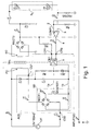
- Fig. 1 illustrates a first embodiment of an inventive electronic circuit, used for powering an LED signal lamp with a constant current, by means of a low frequency (typically ⁇ 100 Hz), low voltage (typically ⁇ 36 V) current source.
- a low frequency typically ⁇ 100 Hz
- low voltage typically ⁇ 36 V
- a 12V / 50 Hz AC (alternating current) voltage is present at a voltage input LVI.
- the voltage input LVI is connected to a series connection of a primary coil PC of a transformer TR1 and an AC switch ACS, with its current contacts CU1 and CU2.
- the winding ratio of windings of the primary coil to the secondary coil NP/NS is 1: 10 in the example shown.
- the voltage at the secondary coil SC is rectified at the second rectifier RECT2 (here a bridge rectifier) and used for loading a loading capacitor C2.
- the loading capacitor C2 powers a signal lamp SL, comprising twelve power LEDS LED1-LED12 connected in series.
- the LED current K through the signal lamp SL also flows through a monitoring resistor RM connected in series with the signal lamp SL.
- a voltage tapped at the monitoring resistor RM is fed into a comparator COMP1 at a second comparator input 3.
- the first comparator input 2 is connected to a control voltage input, denominated with INPUT1 in Fig. 1, which provides a control voltage E. Note that the control voltage E may be constant, or may be variable in order to adjust the brightness of the signal lamp SL.
- the first comparator input 2 is also connected to earth with a resistor R4.
- the LED current K is controlled in a way such that the LED current K is not allowed to exceed a critical value.
- the voltage at the second comparator input 3 is proportional to the LED current K.
- a comparator output 4 is put to earth potential.
- current may flow through a light emitting diode (LED) 5 of an optocoupler OK1, namely from the loading capacitor C2 through a resistor R3, through LED 5 and to comparator output 4.
- LED light emitting diode
- the optocoupler OK1 becomes conductive and short-circuits the switching inputs 1a, 1 b of a switching device SD of the AC switch ACS.
- a switching transistor MOSFET1 of the switching device SD blocks. This means the left and right contacts of a first bridge rectifier RECT1 of the switching device SD are disconnected, such that the current contacts CU1 and CU2 of the AC switch ACS are no more electrically connected.
- the disconnection of the current contacts CU1, CU2 prevents a current flow through the primary coil PC, and the loading capacitor C2 is no more loaded.
- the loading capacitor C2 is discharged due to powering the LEDs LED1-LED12 of the signal lamp SL and the LED 5 of the optocoupler OK1. This means the voltage at the loading capacitor C2 is gradually reduced, and as a consequence the LED current K is reduced, too.
- the comparator COMP1 shuts down the current through LED5.
- the optocoupler OK1 becomes non-conductive again.
- a voltage is built up, which is tapped by a starting resistor R2 and provided to the gate of the switching transistor MOSFET1 at the first switching input 1 a. This voltage makes the switching transistor MOSFET1 conductive again, and current may flow through the first bridge rectifier RECT1 and the primary coil PC again.
- the loading of the loading capacitor C2 is resumed.
- Fig. 2 shows another embodiment of an inventive electronic circuit, which works basically the same as the embodiment of Fig. 1. Therefore, only the differences are detailed below.
- the switching device SD comprises a triac 6 connected to the current contacts CU1, CU2 of the AC switch ACS.
- the triac 6 is controlled by a zero crossing switch 7.
- the switching inputs 1a, 1 b connect the control inputs of the zero crossing switch 7 with the optocoupler OK1.
- This embodiment is particularly resistant to RF interferences.
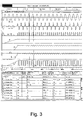
- the voltage input VLI provides continuously a 12V, 50 Hz AC voltage (see line B-C).
- the AC switch ACS blocks, since the switching transistor MOSFET1 does not have a sufficient potential at its gate. Consequently, all input voltage drops across the AC switch ACS, see line H-C.
- the starting capacitor C1 is sufficiently loaded, and the AC switch ACS becomes conductive (see line W-B, indicating no more voltage drops across MOSFET1).
- the AC switch ACS becomes conductive (see line W-B, indicating no more voltage drops across MOSFET1).
- most of the voltage provided by the voltage input LVI now drops across the primary coil PC, and only few of the voltage drops across the current contacts CU1, CU2 of the AC switch ACS (see line H-C).
- the loading capacitor C2 is slowly loaded (see line F).
- the voltage at the loading capacitor is sufficient to exceed the sum of band gaps of the LEDs LED1-LED12 of the signal lamp SL, and an increasing LED current K (see line K) is registered. At the same time, the voltage across the measuring resistor RM (see line G) rises.
- the comparator COMP1 switches off the AC switch.
- the comparator COMP1 sets the comparator output 4 to earth potential, i.e. zero potential here (see line D). This causes the LED 5 to shine, and the optocoupler OK1 becomes conductive. This, in turn, makes the switching transistor MOSFET1 to block, what results in a voltage drop across the switching transistor MOSFET 1 (see line W-B). The input voltage drops again across the AC switch ACS (see line H-B), and the transformer TR1 cannot load the loading transistor C2 any more.
- the voltage at position F drops, as does the LED current K.
- the potential at position G decreases.
- the comparator COMP1 disconnects the comparator output 4 from earth potential (see line D), and the optocoupler OK1 becomes non-conductive again.
- the gate of the switching transistor MOSFET1 at 1 a gets potential again, what means the switching transistor MOSFET1 becomes conductive again (see line W-B), and also the AC switch ACS becomes conductive again (see line H-C).
- the loading of the loading capacitor C2 is resumed, and in particular the potential at position F rises again.
- inventive electronic circuits according to the invention are typically more expensive than the light bulb they replace, the inventive electronic circuits are more economic due to the longer lifetime of the LEDs (with a factor of about 50 more, up to 100.000 hours lifetime for LEDs). In particular, maintenance efforts are reduced.
- the inventive electronic circuit is in particular useful for operating LED signal lamps of railway signals or traffic lights.
Priority Applications (1)
| Application Number | Priority Date | Filing Date | Title |
|---|---|---|---|
| EP06291718A EP1919261A1 (de) | 2006-10-30 | 2006-10-30 | Konstantstromsteuerungseinrichtung auf Niederfrequenz für hochleistungen LED |
Applications Claiming Priority (1)
| Application Number | Priority Date | Filing Date | Title |
|---|---|---|---|
| EP06291718A EP1919261A1 (de) | 2006-10-30 | 2006-10-30 | Konstantstromsteuerungseinrichtung auf Niederfrequenz für hochleistungen LED |
Publications (1)
| Publication Number | Publication Date |
|---|---|
| EP1919261A1 true EP1919261A1 (de) | 2008-05-07 |
Family
ID=37904388
Family Applications (1)
| Application Number | Title | Priority Date | Filing Date |
|---|---|---|---|
| EP06291718A Withdrawn EP1919261A1 (de) | 2006-10-30 | 2006-10-30 | Konstantstromsteuerungseinrichtung auf Niederfrequenz für hochleistungen LED |
Country Status (1)
| Country | Link |
|---|---|
| EP (1) | EP1919261A1 (de) |
Cited By (10)
| Publication number | Priority date | Publication date | Assignee | Title |
|---|---|---|---|---|
| WO2013078667A1 (zh) * | 2011-11-29 | 2013-06-06 | 深圳市华星光电技术有限公司 | 具短路保护的发光二极管驱动电路 |
| CN104429159A (zh) * | 2011-12-16 | 2015-03-18 | 替代照明科技公司 | 近似单位功率因数、寿命长、成本低的led灯改进系统及方法 |
| CN105407576A (zh) * | 2015-12-20 | 2016-03-16 | 合肥艾斯克光电科技有限责任公司 | 一种led驱动电路 |
| CN105491713A (zh) * | 2015-12-23 | 2016-04-13 | 浙江闲兴光电科技有限公司 | 一种大功率led路灯驱动电路 |
| CN105517241A (zh) * | 2015-12-30 | 2016-04-20 | 杭州鸿雁电器有限公司 | 一种控制led灯具亮度切换的方法及亮度切换装置 |
| CN105934045A (zh) * | 2016-07-01 | 2016-09-07 | 安徽亮亮电子科技有限公司 | 一种用于led的单端反激恒流电路 |
| CN106535405A (zh) * | 2016-11-28 | 2017-03-22 | 湖州明日照明科技有限公司 | Led恒流驱动电路 |
| CN106954303A (zh) * | 2017-03-30 | 2017-07-14 | 四川万康节能环保科技有限公司 | 一种电子节能灯用波纹电流抑制型控制电路 |
| WO2018091002A1 (zh) * | 2016-11-16 | 2018-05-24 | 洪学远 | 一种新型智能交通 led 信号灯控制电路及控制机 |
| CN113189387A (zh) * | 2021-05-07 | 2021-07-30 | 湖南银河电气有限公司 | 低频电流电桥和电流比较仪 |
Citations (3)
| Publication number | Priority date | Publication date | Assignee | Title |
|---|---|---|---|---|
| WO1999007059A2 (en) * | 1997-08-01 | 1999-02-11 | Koninklijke Philips Electronics N.V. | Multiresonant dc-dc converter with full-wave rectifying means |
| US6091614A (en) * | 1997-12-17 | 2000-07-18 | Ecolux Inc. | Voltage booster for enabling the power factor controller of a LED lamp upon low ac or dc supply |
| US20060071614A1 (en) * | 2002-12-19 | 2006-04-06 | Koninklijke Philips Electronics N.V. | Leds driver |
-
2006
- 2006-10-30 EP EP06291718A patent/EP1919261A1/de not_active Withdrawn
Patent Citations (3)
| Publication number | Priority date | Publication date | Assignee | Title |
|---|---|---|---|---|
| WO1999007059A2 (en) * | 1997-08-01 | 1999-02-11 | Koninklijke Philips Electronics N.V. | Multiresonant dc-dc converter with full-wave rectifying means |
| US6091614A (en) * | 1997-12-17 | 2000-07-18 | Ecolux Inc. | Voltage booster for enabling the power factor controller of a LED lamp upon low ac or dc supply |
| US20060071614A1 (en) * | 2002-12-19 | 2006-04-06 | Koninklijke Philips Electronics N.V. | Leds driver |
Cited By (17)
| Publication number | Priority date | Publication date | Assignee | Title |
|---|---|---|---|---|
| WO2013078667A1 (zh) * | 2011-11-29 | 2013-06-06 | 深圳市华星光电技术有限公司 | 具短路保护的发光二极管驱动电路 |
| CN104429159A (zh) * | 2011-12-16 | 2015-03-18 | 替代照明科技公司 | 近似单位功率因数、寿命长、成本低的led灯改进系统及方法 |
| CN105407576A (zh) * | 2015-12-20 | 2016-03-16 | 合肥艾斯克光电科技有限责任公司 | 一种led驱动电路 |
| CN105491713A (zh) * | 2015-12-23 | 2016-04-13 | 浙江闲兴光电科技有限公司 | 一种大功率led路灯驱动电路 |
| CN107820350A (zh) * | 2015-12-30 | 2018-03-20 | 杭州鸿雁电器有限公司 | 一种控制led灯具亮度切换的方法及亮度切换装置 |
| CN105517241A (zh) * | 2015-12-30 | 2016-04-20 | 杭州鸿雁电器有限公司 | 一种控制led灯具亮度切换的方法及亮度切换装置 |
| CN108064102A (zh) * | 2015-12-30 | 2018-05-22 | 杭州鸿雁电器有限公司 | 一种控制led灯具亮度切换的方法及亮度切换装置 |
| CN107820350B (zh) * | 2015-12-30 | 2020-04-14 | 杭州鸿雁电器有限公司 | 一种控制led灯具亮度切换的方法及亮度切换装置 |
| CN108064102B (zh) * | 2015-12-30 | 2020-04-14 | 杭州鸿雁电器有限公司 | 一种控制led灯具亮度切换的方法及亮度切换装置 |
| CN105934045A (zh) * | 2016-07-01 | 2016-09-07 | 安徽亮亮电子科技有限公司 | 一种用于led的单端反激恒流电路 |
| WO2018091002A1 (zh) * | 2016-11-16 | 2018-05-24 | 洪学远 | 一种新型智能交通 led 信号灯控制电路及控制机 |
| US10720052B2 (en) | 2016-11-16 | 2020-07-21 | Hokyuen HUNG | Intelligent control circuit and controller for traffic LED signal lamp |
| CN106535405A (zh) * | 2016-11-28 | 2017-03-22 | 湖州明日照明科技有限公司 | Led恒流驱动电路 |
| CN106954303A (zh) * | 2017-03-30 | 2017-07-14 | 四川万康节能环保科技有限公司 | 一种电子节能灯用波纹电流抑制型控制电路 |
| CN106954303B (zh) * | 2017-03-30 | 2018-10-02 | 乐清市风杰电子科技有限公司 | 一种电子节能灯用波纹电流抑制型控制电路 |
| CN109462911A (zh) * | 2017-03-30 | 2019-03-12 | 高路生 | 一种电子节能灯用波纹电流抑制型控制电路 |
| CN113189387A (zh) * | 2021-05-07 | 2021-07-30 | 湖南银河电气有限公司 | 低频电流电桥和电流比较仪 |
Similar Documents
| Publication | Publication Date | Title |
|---|---|---|
| EP1919261A1 (de) | Konstantstromsteuerungseinrichtung auf Niederfrequenz für hochleistungen LED | |
| EP2914065B1 (de) | Beleuchtungslampe und beleuchtungsvorrichtung | |
| US8183795B2 (en) | LED current-supplying circuit and LED current-controlling circuit | |
| US8080947B2 (en) | Current-sharing transformer and power supply circuit having such current-sharing transformer | |
| AU2008264218B2 (en) | LEDs tricolor power signal | |
| US20150341994A1 (en) | Led circuit and driving method thereof | |
| US7218063B2 (en) | Two light level ballast | |
| US20120256550A1 (en) | Led driving circuit | |
| JP5770392B2 (ja) | 少なくとも1つの負荷のドライバ回路及びその動作方法 | |
| JP2008198915A (ja) | 発光装置 | |
| CA2993576C (en) | Long life, fail safe traffic light | |
| EP2317825A2 (de) | Lampenschaltung | |
| JP6607274B2 (ja) | 照明器具 | |
| EP1916879A1 (de) | Sichere opto-elektronische Ausfallerkennung für Hochleistungsleuchtdioden | |
| US20110006605A1 (en) | Current-sharing supply circuit for driving multiple sets of dc loads | |
| CN103379711A (zh) | Led照明装置 | |
| US10959310B2 (en) | Solid-state lighting with complementary controls | |
| EP3716731B1 (de) | Isoliertes treibermodul mit anzeige-led zur kommunikation | |
| JP6424977B2 (ja) | 照明装置 | |
| WO2016003055A1 (ko) | 엘이디 램프 구동장치 | |
| US20200146124A1 (en) | Solid-State Lighting With Multiple Controls And Tests | |
| KR102040513B1 (ko) | 엘이디 램프 구동 제어 장치 및 그 제어방법 | |
| JP5099432B2 (ja) | Led点灯装置およびled標識灯 | |
| KR20160027469A (ko) | 별도의 배선추가 없이 교류전원 벽스위치를 이용한 led 조명제어장치 및 그 제어 방법 | |
| EP2445318A1 (de) | LED-Signallampe mit Konstantstrombetrieb |
Legal Events
| Date | Code | Title | Description |
|---|---|---|---|
| PUAI | Public reference made under article 153(3) epc to a published international application that has entered the european phase |
Free format text: ORIGINAL CODE: 0009012 |
|
| AK | Designated contracting states |
Kind code of ref document: A1 Designated state(s): AT BE BG CH CY CZ DE DK EE ES FI FR GB GR HU IE IS IT LI LT LU LV MC NL PL PT RO SE SI SK TR |
|
| AX | Request for extension of the european patent |
Extension state: AL BA HR MK RS |
|
| AKX | Designation fees paid | ||
| STAA | Information on the status of an ep patent application or granted ep patent |
Free format text: STATUS: THE APPLICATION IS DEEMED TO BE WITHDRAWN |
|
| 18D | Application deemed to be withdrawn |
Effective date: 20081108 |
|
| REG | Reference to a national code |
Ref country code: DE Ref legal event code: 8566 |