EP1918631A2 - Leckeindämmungssystem für reaktive Gase - Google Patents
Leckeindämmungssystem für reaktive Gase Download PDFInfo
- Publication number
- EP1918631A2 EP1918631A2 EP07119579A EP07119579A EP1918631A2 EP 1918631 A2 EP1918631 A2 EP 1918631A2 EP 07119579 A EP07119579 A EP 07119579A EP 07119579 A EP07119579 A EP 07119579A EP 1918631 A2 EP1918631 A2 EP 1918631A2
- Authority
- EP
- European Patent Office
- Prior art keywords
- gas
- fluid storage
- enclosure
- storage vessel
- fluid flow
- Prior art date
- Legal status (The legal status is an assumption and is not a legal conclusion. Google has not performed a legal analysis and makes no representation as to the accuracy of the status listed.)
- Granted
Links
Images


Classifications
-
- F—MECHANICAL ENGINEERING; LIGHTING; HEATING; WEAPONS; BLASTING
- F17—STORING OR DISTRIBUTING GASES OR LIQUIDS
- F17C—VESSELS FOR CONTAINING OR STORING COMPRESSED, LIQUEFIED OR SOLIDIFIED GASES; FIXED-CAPACITY GAS-HOLDERS; FILLING VESSELS WITH, OR DISCHARGING FROM VESSELS, COMPRESSED, LIQUEFIED, OR SOLIDIFIED GASES
- F17C13/00—Details of vessels or of the filling or discharging of vessels
- F17C13/12—Arrangements or mounting of devices for preventing or minimising the effect of explosion ; Other safety measures
- F17C13/123—Arrangements or mounting of devices for preventing or minimising the effect of explosion ; Other safety measures for gas bottles, cylinders or reservoirs for tank vehicles or for railway tank wagons
-
- H—ELECTRICITY
- H10—SEMICONDUCTOR DEVICES; ELECTRIC SOLID-STATE DEVICES NOT OTHERWISE PROVIDED FOR
- H10P—GENERIC PROCESSES OR APPARATUS FOR THE MANUFACTURE OR TREATMENT OF DEVICES COVERED BY CLASS H10
- H10P95/00—Generic processes or apparatus for manufacture or treatments not covered by the other groups of this subclass
-
- F—MECHANICAL ENGINEERING; LIGHTING; HEATING; WEAPONS; BLASTING
- F17—STORING OR DISTRIBUTING GASES OR LIQUIDS
- F17C—VESSELS FOR CONTAINING OR STORING COMPRESSED, LIQUEFIED OR SOLIDIFIED GASES; FIXED-CAPACITY GAS-HOLDERS; FILLING VESSELS WITH, OR DISCHARGING FROM VESSELS, COMPRESSED, LIQUEFIED, OR SOLIDIFIED GASES
- F17C2205/00—Vessel construction, in particular mounting arrangements, attachments or identifications means
- F17C2205/03—Fluid connections, filters, valves, closure means or other attachments
- F17C2205/0302—Fittings, valves, filters, or components in connection with the gas storage device
- F17C2205/0308—Protective caps
-
- F—MECHANICAL ENGINEERING; LIGHTING; HEATING; WEAPONS; BLASTING
- F17—STORING OR DISTRIBUTING GASES OR LIQUIDS
- F17C—VESSELS FOR CONTAINING OR STORING COMPRESSED, LIQUEFIED OR SOLIDIFIED GASES; FIXED-CAPACITY GAS-HOLDERS; FILLING VESSELS WITH, OR DISCHARGING FROM VESSELS, COMPRESSED, LIQUEFIED, OR SOLIDIFIED GASES
- F17C2260/00—Purposes of gas storage and gas handling
- F17C2260/03—Dealing with losses
- F17C2260/035—Dealing with losses of fluid
-
- Y—GENERAL TAGGING OF NEW TECHNOLOGICAL DEVELOPMENTS; GENERAL TAGGING OF CROSS-SECTIONAL TECHNOLOGIES SPANNING OVER SEVERAL SECTIONS OF THE IPC; TECHNICAL SUBJECTS COVERED BY FORMER USPC CROSS-REFERENCE ART COLLECTIONS [XRACs] AND DIGESTS
- Y10—TECHNICAL SUBJECTS COVERED BY FORMER USPC
- Y10T—TECHNICAL SUBJECTS COVERED BY FORMER US CLASSIFICATION
- Y10T137/00—Fluid handling
- Y10T137/0318—Processes
- Y10T137/0402—Cleaning, repairing, or assembling
- Y10T137/0441—Repairing, securing, replacing, or servicing pipe joint, valve, or tank
- Y10T137/0452—Detecting or repairing leak
-
- Y—GENERAL TAGGING OF NEW TECHNOLOGICAL DEVELOPMENTS; GENERAL TAGGING OF CROSS-SECTIONAL TECHNOLOGIES SPANNING OVER SEVERAL SECTIONS OF THE IPC; TECHNICAL SUBJECTS COVERED BY FORMER USPC CROSS-REFERENCE ART COLLECTIONS [XRACs] AND DIGESTS
- Y10—TECHNICAL SUBJECTS COVERED BY FORMER USPC
- Y10T—TECHNICAL SUBJECTS COVERED BY FORMER US CLASSIFICATION
- Y10T137/00—Fluid handling
- Y10T137/5762—With leakage or drip collecting
-
- Y—GENERAL TAGGING OF NEW TECHNOLOGICAL DEVELOPMENTS; GENERAL TAGGING OF CROSS-SECTIONAL TECHNOLOGIES SPANNING OVER SEVERAL SECTIONS OF THE IPC; TECHNICAL SUBJECTS COVERED BY FORMER USPC CROSS-REFERENCE ART COLLECTIONS [XRACs] AND DIGESTS
- Y10—TECHNICAL SUBJECTS COVERED BY FORMER USPC
- Y10T—TECHNICAL SUBJECTS COVERED BY FORMER US CLASSIFICATION
- Y10T137/00—Fluid handling
- Y10T137/6851—With casing, support, protector or static constructional installations
- Y10T137/7043—Guards and shields
- Y10T137/7062—Valve guards
Definitions
- Reactive gases are used in many process steps in the fabrication of microelectronic components, optical components, analytical instruments, and other specialized equipment. Most of these reactive gases are highly hazardous to operating personnel, and the manufacture, storage, transportation, and end use of these gases must be carried out under strict safety procedures. These gases are transported and stored at ambient temperatures in pressurized cylinders either as compressed gases or as pressurized saturated liquids.
- the pressurized cylinders may be individual standalone cylinders or may be multiple-tube bundles used in tube trailers or ISO containers.
- Each storage cylinder is fabricated with at least one discharge port, and the port typically is threaded for the installation of fluid flow fittings such as shutoff valves, bull plugs, and other fittings that are connected in turn to valve and piping systems that supply gas to an end user.
- Leaks may occur in a fluid flow fitting at threaded connections, compression fittings, O-ring seals, valve stem packings, and valve seats. In many cases, these leaks are small (e.g., less than about 50 sccm), but even small leaks can be hazardous and may develop into larger and possibly catastrophic leaks. If leaks occur at an operating plant in which the cylinders are filled, appropriate safety equipment and procedures will be available to contain the leak and repair the leaking components. If leaks occur during cylinder transportation or while a cylinder is stored at a user's site, however, appropriate equipment and procedures to contain the leak and repair the leaking components may not be available.
- One embodiment of the invention provides a fluid storage and leak containment system comprising (a) a fluid storage vessel system comprising at least one vessel having an interior, an exterior, and an outlet opening between the interior and the exterior; (b) a fluid flow fitting sealably connected to the outlet opening and adjacent the exterior of the at least one vessel, wherein the fluid flow fitting is adapted for withdrawing reactive gas from the interior of the vessel; and (c) a containment enclosure having an interior, an exterior, an open end, and an extraction port adapted for the withdrawal of gas from the interior of the containment enclosure, wherein the open end is adapted to fit over and around the fluid flow fitting such that the containment enclosure surrounds the fluid flow fitting and is adapted to collect any reactive gas leaking from the fluid flow fitting.
- a leak containment cap comprising an enclosure having an interior, an exterior, an open end, and an extraction port adapted for the withdrawal of gas from the interior of the enclosure, wherein the open end is adapted to fit over and around a fluid flow fitting that is connected to an outlet of a fluid storage vessel of a fluid storage vessel system, and wherein the enclosure is adapted to surround the fluid flow fitting and contact the fluid storage vessel system; and a removable attachment member connected to the containment enclosure, wherein the removable attachment member is adapted to removably attach the containment enclosure to the fluid storage vessel system and to press the open end of the enclosure against the fluid storage vessel system around the fluid flow fitting.
- the embodiments of the present invention provide methods and systems for collecting and capturing reactive gas that escapes from a leaking fluid storage vessel system.
- the collection system may be operated to capture the leaking reactive gas until the fluid storage vessel system can be repaired by withdrawing the reactive gas from the storage vessel system and replacing the leaking components.
- the collection system may be operated during transportation of the fluid storage vessel system to a repair facility.
- the collection system may be carried in the inventory of an emergency response vehicle for immediate delivery to a leak site to capture gas leaking from a fluid storage vessel system.
- the collection system also may be carried on a truck or a cab/trailer of a mobile fluid storage vessel system so that the collection system is available for immediate use if a leak occurs.
- the fluid storage vessel system may be, for example, a plurality of horizontal cylinders assembled in a tube trailer, a plurality of horizontal cylinders assembled as an ISO container transportable by flatbed trailer, or individual cylinders carried on a truck or cab/trailer.
- Reactive gases are stored in pressurized cylinders at ambient temperatures either as compressed gases or as pressurized saturated liquids.
- the pressurized cylinders may be individual standalone cylinders or may be bundles of horizontal cylinders assembled in tube trailers or in ISO containers as described above.
- Pressurized fluid storage cylinders are fabricated with at least one discharge port, and the port typically is threaded internally for the installation of fluid flow fittings that comprise bull plugs, shutoff valves, connections to piping leading to safety relief devices, and connections to end user gas delivery piping.
- Leaks may occur in a fluid flow fitting at threaded, O-ring, flared, or ferrule-type connections between the fluid flow fitting and valves or external piping systems, at a valve stem packing, or across a valve seat.
- fluid storage vessel system is defined as a system comprising one or more fluid storage vessels, for example cylinders, designed for the storage of pressurized fluids including compressed gases and pressurized liquids.
- Fluid storage vessel systems include single standalone cylinders, multiple cylinders grouped and assembled for mounting on trucks or trailers, and multiple cylinders grouped and assembled in a framework as shippable ISO containers.
- a fluid storage vessel system thus includes any cylinder or group of cylinders containing compressed gas or pressurized liquid, wherein each cylinder includes an associated fluid flow fitting.
- a fluid flow fitting is a device connected to an outlet of a fluid storage vessel through which gas flows during withdrawal from the vessel.
- the fluid flow fitting includes one or more parts including but not limited to bull plugs, tees, connectors, O-ring seals, pipe thread joints, compression fittings, piping segments, and shutoff valves.
- reactive gas is defined as any gas that reacts with liquids, solids, or other gases to form reaction products accompanied by the generation of heat.
- reactive material is defined as any liquid and/or solid material that reacts with a reactive gas to form reaction products, thereby capturing and immobilizing the reactive gas. The reactive material may undergo a chemical reaction with the reactive gas and/or adsorb the reactive gas.
- removably attached refers to an attachment as for example provided by an attachment member connected to a containment enclosure as described below wherein the attachment member is adapted to be attached to and detached from a fluid storage vessel system.
- the attachment member may be removably connected to the containment enclosure or may be permanently connected to the containment enclosure.
- in flow communication with means that gas can flow from the first region to the second region through connecting piping and/or an intermediate region.
- a repair facility is defined as a facility equipped and manned for the safe handling, processing, and repairing of a fluid storage vessel system that is leaking a reactive gas.
- indefinite articles “a” and “an” as used herein mean one or more when applied to any feature in embodiments of the present invention described in the specification and claims. The use of “a” and “an” does not limit the meaning to a single feature unless such a limit is specifically stated.
- the definite article “the” preceding singular or plural nouns or noun phrases denotes a particular specified feature or particular specified features and may have a singular or plural connotation depending upon the context in which it is used.
- the adjective “any” means one, some, or all indiscriminately of whatever quantity.
- the term “and/or” placed between a first entity and a second entity means one of (1) the first entity, (2) the second entity, and (3) the first entity and the second entity.
- Cylinder 1 has neck portion 3 supported in a circular opening in bulkhead 5 such that the bulkhead supports the vertical component of the cylinder weight and the cylinder is free to rotate slightly in the circular opening when the cylinder twists about its axis due to torsional forces.
- Neck 3 is threaded on the outer surface, and retaining collar 7 is threaded over the neck to locate and retain the cylinder in the axial direction.
- Cylinder 1 typically is supported at the other end in a similar support bulkhead, and the entire cylinder assembly is mounted on a truck or trailer by methods known in the art.
- cylinder 1 may be one of a plurality of cylinders grouped in a similar manner and mounted in an ISO-type container framework.
- Neck 3 is internally threaded to receive externally-threaded bull plug 9, which has a center internally-threaded opening to receive an externally-threaded end of tee fitting 11.
- the seal between bull plug 9 and neck 3 is provided by an O-ring (not shown).
- Tee fitting 11 has an internally-threaded opening at the other end to receive an externally-threaded end of shutoff valve 13, and the valve is equipped with valve stem 15 mounted in valve packing section 17.
- Pigtail 19 which is connected to the outlet of valve 13 by compression fitting 21, supplies gas to a supply manifold (not shown) that is connected in turn to an end user's gas supply system.
- Tee fitting 11 also has an internally-threaded opening on the top section to receive one end of externally-threaded compression fitting body 23.
- Tube 25 is connected by compression fitting 27 at the other end of compression fitting body 23 and leads to a safety relief device (not shown).
- a safety relief device is not used, and tee fitting 11, externally-threaded compression fitting body 23, tube 25, and compression fitting 27 are not required.
- the fluid flow fitting of Fig. 1 may leak at any of the threaded and compression fittings shown or at the stem packing of shutoff valve 13. It has been observed in the development of the embodiments described below that leaks occur most often at the O-ring seal between cylinder neck 3 and bull plug 9. When such a leak occurs, replacement of the O-ring and possibly the bull plug is required, and the pressurized fluid in cylinder 1 must be withdrawn before this replacement can be effected. When leaks occur at the threaded or compression fitting connections on tee 11 as described above, cylinder 1 also must be emptied before replacement or repair of the leaking components can be effected. These repairs usually must be carried out in a central cylinder fill and maintenance facility.
- Embodiments of the invention include a containment enclosure that fits over and around the fluid flow fitting such that the containment enclosure surrounds the fluid flow fitting and is adapted to collect any reactive gas leaking from the fluid flow fitting.
- a typical containment enclosure is illustrated in Fig. 2 wherein containment enclosure 201 fits over and around fluid flow fitting 203 and is placed in contact with bulkhead 5.
- pigtail 9 and fitting 21 of Fig. 1 are removed before placement of containment enclosure 201.
- Slot 205 is provided in the wall of containment enclosure 201 so that the enclosure can be slipped over tube 25. As described later, this slot can be closed off (but typically not sealed) by appropriate methods using adhesive tape or a fabric with a hook-and-loop closure.
- At least one extraction port is provided for the withdrawal of collected leaking gas from the interior of the containment enclosure.
- two ports are provided - small port 207 for withdrawing gas from smaller leaks and larger port 209 for withdrawing gas from larger leaks.
- the port not in use can be plugged as needed (not shown).
- the containment enclosure may be fabricated from any metal, plastic, or composite material that is compatible with the leaking gas.
- a system that does not require a safety relief device does not have tee fitting 11, externally-threaded compression fitting body 23, tube 25, and compression fitting 27.
- pigtail 19 is not removed and enclosure 201 can be placed over and around fluid flow fitting 203 such that slot 205 slides over pigtail 19.
- this slot can be closed off (but typically not sealed) by appropriate methods using adhesive tape or a fabric with a hook-and-loop closure.
- Fig. 3 is a view of section A-A of Fig. 2 showing containment enclosure 201 fitting over and around fluid flow fitting 203 in contact with bulkhead 5 outside of retaining collar 7. Slot 205 is shown in the wall of containment enclosure 201 allowing the enclosure to be slipped over tube 25.
- Containment enclosure 201 may be removably attached to the fluid storage vessel system around fluid flow fitting 203 when a leak occurs and detached for storage when the leak is repaired.
- the enclosure may be attached by any type of detachable connection system that is adapted to hold the enclosure in place around the fitting and against bulkhead 5.
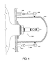
- detachable connection system is illustrated in the embodiment of Fig. 4, which is a bottom view orthogonal to the view of Fig. 2 showing containment enclosure 201 in section.
- two elastic bodies or cords 401 and 403 are attached to containment enclosure 201 by eyebolts 405 and 407.
- the elastic cords are attached at the opposite ends to magnets 409 and 411 that are removably attached to bulkhead 5 (which typically is steel), thereby placing elastic cords in tension and forcing containment enclosure 201 against bulkhead 5.
- the elastic cords may be, for example, bungee cords or any other elastomeric material appropriate for the purpose of forcing containment enclosure 201 against bulkhead 5.
- eyebolts may be permanently attached to bulkhead 5 on either side of fluid flow fitting 203, and elastomeric cords or springs of appropriate length may be attached at one end to eyebolts 405 and 407 and provided with hooks at the other end for connection to the eyebolts on bulkhead 5.
- elastomeric cords or springs of appropriate length may be attached at one end to eyebolts 405 and 407 and provided with hooks at the other end for connection to the eyebolts on bulkhead 5.
- Other types of detachable connection systems can be envisioned to provide for the attachment and detachment of containment enclosure 201 to bulkhead 5.
- FIG. 5 An external view of the embodiment of Fig. 4 is given in Fig. 5 showing containment enclosure 201, slot 205, elastic bodies or cords 401 and 403 (not in tension), eyebolts 405 and 407, and magnets 409 and 411.
- larger port 209 is closed off by cap 501.
- the combination of containment enclosure 201 with elastic bodies or cords 401 and 403, eyebolts 405 and 407, and magnets 409 and 411 may be defined as a type of leak containment cap.
- a leak containment cap is defined generically as the combination of any containment enclosure adapted for leak containment as described above and any attachment member connectable to the containment enclosure.
- the attachment member is adapted to removably attach the containment enclosure to a fluid storage vessel system and to press the open end of the enclosure against the fluid storage vessel system around the fluid flow fitting as described above.
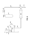
- Leaking gas collected by containment enclosure 201 may be processed and captured by the embodiment illustrated in Fig. 6.
- containment enclosure 201 is attached to bulkhead 5 by the elastic cords and magnets of Figs. 4 and 5 (cord 403, eyebolt 407, and magnet 411 are shown here).
- the opening of enclosure 201 is pressed against bulkhead 5 but preferably does not form a completely gas tight seal.
- Slot 205 is loosely closed around tube 25 using adhesive tape or hook-and-loop fabric (not shown).
- Small port 207 is connected to line 601 and larger port 209 is capped as shown.
- Line 601 is in flow communication with the inlet of scrubbing vessel 603 containing reactive material that reacts with and captures the gas leaking from the fluid storage vessel system.
- the reactive material may undergo a chemical reaction with the leaking gas and/or adsorb and/or absorb the gas, thereby capturing and immobilizing the gas.
- the outlet of scrubbing vessel 603 is connected in flow communication with the aspirated inlet of venturi eductor 605, and line 607 is connected to the high pressure motive gas inlet of the eductor.
- Scrubbing vessel 603 is made of any material compatible with the leaking gas to be treated therein and compatible with the temperatures that occur during reaction with the collected gas.
- Line 607 is in flow communication with pressure regulator 609 mounted on high pressure gas supply cylinder 611, which provides gas for flow through venturi eductor 605 to generate a low pressure at the aspirated inlet.
- the high pressure gas may be, for example, nitrogen, other inert gas, or compressed air.
- Scrubbing vessel 603 is sized to process a relatively small gas leakage rate, for example, less that about 50 sccm, for up to about 100 hours. This vessel typically has a volume of approximately 2500 cm 3 .
- the venturi eductor is operated to generate a slightly subatmospheric pressure at the aspirated inlet, thereby drawing gas from containment enclosure 201 through line 601 and scrubbing vessel 603. Because containment enclosure 201 is not completely sealed, an amount of atmospheric air enters the enclosure, thereby acting as a purge gas that mixes with the leaking reactive gas. This gas mixture is treated in scrubbing vessel 603, wherein the reactive gas is captured, and clean gas is vented to the atmosphere via line 613.
- the reactive material used in scrubbing vessel 603 will depend on the reactive nature of the leaking gas and should be selected to properly react with and capture the leaking gas.
- the reactive material may be a caustic neutralizer such as sodium hydroxide or potassium hydroxide for capturing acid gases such as anhydrous ammonia. Other caustic reactive materials may be used as appropriate.
- Scrubbing vessel 603 may be fabricated from a plastic material such as, for example, polyvinyl chloride (PVC). Alternatively, the scrubbing vessel may be fabricated from any appropriate metal such as carbon steel, stainless steel, or other corrosion-resistant alloys.
- the containment system of Fig. 6 may be carried on a cylinder delivery truck or a tube trailer for immediate use when a small leak, for example less than 50 sccm, occurs.
- the containment system of Fig. 6 also may be carried on an emergency response (ER) vehicle for transportation to a leak site.
- ER emergency response
- venturi eductor 605 may be installed at the inlet to scrubbing vessel 603 such that the discharge of the eductor via line 613 passes through the scrubbing vessel.
- the scrubbing vessel processes a mixture containing the reactive gas, air entering containment enclosure 201, and motive gas from venturi eductor 603.
- a vacuum pump may be used instead of the venturi eductor at either the inlet or outlet of scrubbing vessel 603.
- gas collected by containment enclosure 201 may be processed and captured by the embodiment illustrated in Fig. 7.
- containment enclosure 201 is attached to bulkhead 5 as described above.
- the opening of enclosure 201 is pressed against bulkhead 5 but preferably does not form a completely gas tight seal.
- Slot 205 is loosely closed around tube 25 using adhesive tape or hook-and-loop fabric (not shown).
- Large port 209 is connected to flexible hose 701 and smaller port 207 is capped as shown.
- Hose 701 is in flow communication with the aspirated inlet of venturi eductor 703, which discharges into scrubbing drum 705 that contains a bed of reactive material that reacts with and captures the gas leaking from the fluid storage vessel system.
- the reactive material may undergo a chemical reaction with the leaking gas and/or adsorb the gas and/or absorb the gas, thereby capturing and immobilizing the gas.
- the bed of reactive material is contained by appropriate support screens within drum 705 so that treated gas can exit via vent holes 707 in the bottom of the drum.
- venturi eductor 705 The motive gas inlet of venturi eductor 705 is connected via line 709 to pressure regulator 711 mounted on high pressure gas supply cylinder 713, which provides gas for flow through venturi eductor 703 to generate a low pressure at the aspirated inlet.
- the high pressure gas may be, for example, nitrogen, other inert gas, or compressed air.
- Scrubbing drum 705 is sized to process a larger gas leakage rate, for example, greater than 50 sccm, for an operating period of several hours up to 100 hours. This drum typically has a volume of 200 to 250 liters.
- Venturi eductor 703 is operated to generate a slightly subatmospheric pressure at the aspirated inlet, thereby drawing gas from containment enclosure 201 through hose 701 and discharging it into scrubbing drum 705. Because containment enclosure 201 is not completely sealed, an amount of atmospheric air enters the enclosure, thereby acting as a purge gas that mixes with the leaking reactive gas. This gas mixture and the motive gas from venturi eductor 703 are treated in scrubbing drum 705, wherein the reactive gas is captured, and clean gas is vented to the atmosphere via openings 707.
- the reactive material used in scrubbing drum 705 will depend on the reactive nature of the leaking gas and is selected to properly react with and capture the leaking gas.
- the reactive material may be a caustic neutralizer such as sodium hydroxide or potassium hydroxide for capturing acid gases such as anhydrous ammonia. Other caustic reactive materials may be used as appropriate.
- Scrubbing drum 705 may be fabricated from a plastic material such as, for example, polyvinyl chloride (PVC). Alternatively, the scrubbing drum may be fabricated from any appropriate metal such as carbon steel, stainless steel, or other corrosion-resistant alloys.
- the leak containment system of Fig. 7 typically is transported to a leak site by an emergency response vehicle.
- An ISO-type multiple-cylinder module containing a fluorine-nitrogen mixture is offloaded from a ship at a port.
- An emergency response team is present during the offloading according to standard practice in order to check the module before land transport to the customer.
- the ER team detects a small leak of about 1x10 -3 cm 3 /sec at the bull plug of one of the cylinders. While this leak is minor, the toxicity of fluorine and the low odor threshold of the leaking gas prohibit land transportation of the module to the customer.
- the leaking cylinder could be handled at the dock by the ER team by emptying the leaking cylinder and reacting the withdrawn gas with scrubbing material to immobilize the gas. However, this approach could take up to 48 hours, would have some associated risk, and would require closure of the dock area during the procedure. This could result in a significant economic penalty because of the dock area closure.
- the ER team decides to handle the leak by utilizing the containment cap described above with reference to Figs. 2-5 and the process of Fig. 6.
- the cylinder does not have a safety relief device and therefore does not have tee fitting 11, externally-threaded compression fitting body 23, tube 25, and compression fitting 27.
- enclosure 201 is placed over and around fluid flow fitting 203 such that slot 205 slides over pigtail 19.
- Containment enclosure 201 is placed over the leaking fluid flow fitting, and magnets 409 and 411 are attached to the ISO module to hold the containment enclosure in place.
- Slot 205 fits over the pigtail and is partially closed off using duct tape to allow some leakage of ambient air into containment enclosure 201.
- Line 601 is attached to outlet 207, pressurized nitrogen flow is initiated from cylinder 611 via line 607 through venturi eductor 605, and a mixture of leaking gas and inflowing air is withdrawn from containment enclosure 201 and through scrubbing vessel 603, wherein the reactive gas is captured by alumina. Clean gas is vented to the atmosphere via line 613.
- the ISO container While gas withdrawal and treatment continues, the ISO container is transported by truck and followed by the ER team to a production facility with the proper equipment to handle the leak and repair the leaking cylinder. Because the ISO module is no longer at the dock, the dock area can be reopened for normal operation.
Landscapes
- Engineering & Computer Science (AREA)
- Mechanical Engineering (AREA)
- General Engineering & Computer Science (AREA)
- Filling Or Discharging Of Gas Storage Vessels (AREA)
Applications Claiming Priority (1)
| Application Number | Priority Date | Filing Date | Title |
|---|---|---|---|
| US11/590,029 US7448402B2 (en) | 2006-10-31 | 2006-10-31 | Leak containment apparatus for reactive gases |
Publications (3)
| Publication Number | Publication Date |
|---|---|
| EP1918631A2 true EP1918631A2 (de) | 2008-05-07 |
| EP1918631A3 EP1918631A3 (de) | 2010-10-06 |
| EP1918631B1 EP1918631B1 (de) | 2013-05-08 |
Family
ID=39135294
Family Applications (1)
| Application Number | Title | Priority Date | Filing Date |
|---|---|---|---|
| EP20070119579 Not-in-force EP1918631B1 (de) | 2006-10-31 | 2007-10-30 | Leckeindämmungssystem für reaktive Gase |
Country Status (6)
| Country | Link |
|---|---|
| US (1) | US7448402B2 (de) |
| EP (1) | EP1918631B1 (de) |
| JP (1) | JP4768700B2 (de) |
| KR (1) | KR100967773B1 (de) |
| IL (1) | IL186905A (de) |
| TW (1) | TWI349081B (de) |
Cited By (2)
| Publication number | Priority date | Publication date | Assignee | Title |
|---|---|---|---|---|
| CN104110577A (zh) * | 2014-07-15 | 2014-10-22 | 张家港市顺佳隔热技术有限公司 | 车载气罐保护罩 |
| WO2016018685A1 (en) * | 2014-07-28 | 2016-02-04 | Baker Hughes Incorporated | Apparatus and methods for capturing vapors exiting a material storage compartment of a vessel |
Families Citing this family (18)
| Publication number | Priority date | Publication date | Assignee | Title |
|---|---|---|---|---|
| US8042580B2 (en) * | 2004-06-02 | 2011-10-25 | Golden Triangle Enterprises Pty Ltd | Apparatus and method for capturing and containing sulphur hexafluoride gas leakage |
| US20090223982A1 (en) * | 2008-03-06 | 2009-09-10 | Lynn Eric Borne | Protective cover for a valve |
| EP2157353B1 (de) * | 2008-08-13 | 2011-04-27 | Mitsubishi Materials Corporation | Aufbewahrungsbehälter für flüssiges Chlorsilan und Schließdeckel dafür |
| US20100112191A1 (en) * | 2008-10-30 | 2010-05-06 | Micron Technology, Inc. | Systems and associated methods for depositing materials |
| US8590705B2 (en) * | 2010-06-11 | 2013-11-26 | Air Products And Chemicals, Inc. | Cylinder surface treated container for monochlorosilane |
| JP3178325U (ja) * | 2012-06-19 | 2012-09-13 | 仁史 森川 | ガスボンベのバルブ保護キャップ |
| DE102012220106A1 (de) * | 2012-11-05 | 2014-05-08 | Siemens Aktiengesellschaft | Sicherheitssystem in einer Anlage, insbesondere einer Energieerzeugungsanlage |
| TWI531405B (zh) | 2014-12-15 | 2016-05-01 | 財團法人工業技術研究院 | 氫洩漏吸附裝置、氫能利用系統、及氫洩漏吸附方法 |
| RU2742223C1 (ru) * | 2017-06-21 | 2021-02-03 | ДжиСиИ Холдинг АБ | Предохранительное кольцо клапана |
| US10113663B1 (en) * | 2017-08-22 | 2018-10-30 | Foster Supply, Inc. | Water meter locking device |
| JP6654171B2 (ja) * | 2017-08-24 | 2020-02-26 | 本田技研工業株式会社 | 高圧タンク装置及びその漏洩検知方法 |
| CN107504176A (zh) * | 2017-09-20 | 2017-12-22 | 浙江美丽健乳业有限公司 | 储罐 |
| US20190346062A1 (en) * | 2018-05-08 | 2019-11-14 | Michael Wall | Anti-Tamper Device |
| CN109626325A (zh) * | 2018-12-13 | 2019-04-16 | 杨宇 | 一种节能环保氯化氢发生装置 |
| FR3096458B1 (fr) * | 2019-05-21 | 2021-04-23 | Gaztransport Et Technigaz | Dispositif de détection de fuite |
| JP7824764B2 (ja) * | 2021-12-17 | 2026-03-05 | 株式会社Ihiプラント | アンモニアタンク内払出ポンプのメンテナンス方法 |
| CN114905034A (zh) * | 2022-05-26 | 2022-08-16 | 广东韶钢松山股份有限公司 | 一种铁水包补漏装置以及补漏方法 |
| US12529621B2 (en) | 2022-08-04 | 2026-01-20 | Air Products And Chemicals, Inc. | Compressed fluid vessel monitoring apparatus and method |
Family Cites Families (20)
| Publication number | Priority date | Publication date | Assignee | Title |
|---|---|---|---|---|
| US1413502A (en) * | 1919-10-08 | 1922-04-18 | Joseph A Steinmetz | Cap flange for cylinders |
| US4241846A (en) * | 1978-10-16 | 1980-12-30 | William Murphy | Garbage can cover retainer |
| US4478345A (en) * | 1983-06-27 | 1984-10-23 | Edinger William J | Self-contained containment for gas cylinder |
| US4489679A (en) * | 1983-12-12 | 1984-12-25 | Combustion Engineering, Inc. | Control system for economic operation of a steam generator |
| JPH079280B2 (ja) * | 1987-09-09 | 1995-02-01 | 三菱電機株式会社 | ガスボンベの安全取扱い装置 |
| JPH01207923A (ja) * | 1988-02-16 | 1989-08-21 | Toshiba Ceramics Co Ltd | ベンチュリー管型シリコン・ソース気化装置 |
| JPH02253100A (ja) * | 1989-03-24 | 1990-10-11 | Mitsubishi Electric Corp | ガスリーク検出装置 |
| US5086804A (en) * | 1991-01-23 | 1992-02-11 | Solkatronic Chemicals, Inc. | Emergency security device for head of a leaking gas cylinder |
| US5158204A (en) * | 1992-02-06 | 1992-10-27 | Air Products And Chemicals, Inc. | Containment and diversion cap for gas cylinders |
| US5383499A (en) * | 1992-05-04 | 1995-01-24 | Earth Resources Corporation | System for removal of unknown, corrossive, or potentially hazardous gases from a gas container |
| JP3507103B2 (ja) * | 1993-09-20 | 2004-03-15 | 富士通株式会社 | 排気除害システム |
| US5588461A (en) * | 1994-04-08 | 1996-12-31 | Philipp Brothers Chemicals, Inc. | Hazardous material containment system |
| US5482536A (en) * | 1994-04-12 | 1996-01-09 | Solvay Specialty Chemicals, Inc. | Apparatus for containment and scrubbing of toxic gas from a leakage location and method therefor |
| DE19543485C1 (de) * | 1995-11-22 | 1996-11-28 | Tyczka Gmbh & Co | Gasflasche |
| FR2749061B1 (fr) * | 1996-05-21 | 1998-06-26 | Air Liquide | Dispositif de confinement de fuites de gaz de bouteille de gaz |
| US5900216A (en) * | 1996-06-19 | 1999-05-04 | Earth Resources Corporation | Venturi reactor and scrubber with suckback prevention |
| DE20117492U1 (de) * | 2001-10-25 | 2002-01-17 | Plattner Schweißtechnik und Gase GmbH, 94550 Künzing | Chlornotfallkappe |
| DE10308676B4 (de) * | 2003-02-28 | 2008-04-03 | Adam Opel Ag | Schutzkappe für ein Flaschenventil einer Gasflasche |
| KR100812091B1 (ko) * | 2003-12-30 | 2008-03-07 | 동부일렉트로닉스 주식회사 | 화학기계적 연마장비의 배기장치 |
| KR20060078642A (ko) * | 2004-12-30 | 2006-07-05 | 동부일렉트로닉스 주식회사 | 반도체 공정챔버용 진공라인의 역류방지장치 및 그 방법 |
-
2006
- 2006-10-31 US US11/590,029 patent/US7448402B2/en not_active Expired - Fee Related
-
2007
- 2007-10-25 IL IL186905A patent/IL186905A/en active IP Right Grant
- 2007-10-25 JP JP2007277956A patent/JP4768700B2/ja not_active Expired - Fee Related
- 2007-10-26 TW TW096140410A patent/TWI349081B/zh not_active IP Right Cessation
- 2007-10-30 EP EP20070119579 patent/EP1918631B1/de not_active Not-in-force
- 2007-10-30 KR KR1020070109786A patent/KR100967773B1/ko not_active Expired - Fee Related
Cited By (3)
| Publication number | Priority date | Publication date | Assignee | Title |
|---|---|---|---|---|
| CN104110577A (zh) * | 2014-07-15 | 2014-10-22 | 张家港市顺佳隔热技术有限公司 | 车载气罐保护罩 |
| WO2016018685A1 (en) * | 2014-07-28 | 2016-02-04 | Baker Hughes Incorporated | Apparatus and methods for capturing vapors exiting a material storage compartment of a vessel |
| US9364874B2 (en) | 2014-07-28 | 2016-06-14 | Baker Hughes Incorporated | Apparatus and methods for capturing vapors exiting a material storage compartment of a vessel |
Also Published As
| Publication number | Publication date |
|---|---|
| US7448402B2 (en) | 2008-11-11 |
| EP1918631A3 (de) | 2010-10-06 |
| US20080099075A1 (en) | 2008-05-01 |
| TW200819667A (en) | 2008-05-01 |
| TWI349081B (en) | 2011-09-21 |
| JP4768700B2 (ja) | 2011-09-07 |
| KR20080039310A (ko) | 2008-05-07 |
| EP1918631B1 (de) | 2013-05-08 |
| IL186905A0 (en) | 2008-02-09 |
| KR100967773B1 (ko) | 2010-07-05 |
| JP2008116044A (ja) | 2008-05-22 |
| IL186905A (en) | 2011-04-28 |
Similar Documents
| Publication | Publication Date | Title |
|---|---|---|
| EP1918631B1 (de) | Leckeindämmungssystem für reaktive Gase | |
| TWI278577B (en) | Monitoring of ultra-high purity product storage tanks during transportation | |
| CN105531203B (zh) | 用于填充和分配液体的设备和方法 | |
| US9216885B1 (en) | Bladder and engagement device for storage tank | |
| US5158204A (en) | Containment and diversion cap for gas cylinders | |
| EP1037269A1 (de) | Zuführvorrichtung für grosse merge eines prozessgases für halbleiter | |
| CN103372557B (zh) | 一种吹扫净化方法及其装置 | |
| US20110226368A1 (en) | Bundle trailer for gas delivery | |
| US5482536A (en) | Apparatus for containment and scrubbing of toxic gas from a leakage location and method therefor | |
| US6003540A (en) | Device for confining gas leaks from a gas cylinder | |
| US7264013B2 (en) | Enhanced purge effect in gas conduit | |
| CA2226248C (en) | Containment and delivery apparatus for hazardous fluids | |
| TW200304527A (en) | Transportation and storage of ultra-high purity products | |
| CN105444973B (zh) | 低温压力自动增压平衡装置 | |
| US20210300176A1 (en) | Fuel Tank with Internal Bladder and Method | |
| JPH01250699A (ja) | 防災キャップ | |
| JP4879032B2 (ja) | 地下タンクの通気管設備 | |
| US6684899B2 (en) | Apparatus for safely containing and delivering hazardous fluid substances from at least two supply cylinders | |
| US6435227B1 (en) | Tank filling apparatus and method | |
| JP2000257797A (ja) | 減圧機能付き容器弁 | |
| CA2401712C (en) | Device for removing fluid from a container | |
| CN218409526U (zh) | 二氧化碳充装装置 | |
| CN206872067U (zh) | 一种汽车罐车的流体物料卸车装置 | |
| CN115798763B (zh) | 乏燃料贮运容器多功能台架及其工作方法 | |
| JP4121404B2 (ja) | 容器 |
Legal Events
| Date | Code | Title | Description |
|---|---|---|---|
| PUAI | Public reference made under article 153(3) epc to a published international application that has entered the european phase |
Free format text: ORIGINAL CODE: 0009012 |
|
| AK | Designated contracting states |
Kind code of ref document: A2 Designated state(s): AT BE BG CH CY CZ DE DK EE ES FI FR GB GR HU IE IS IT LI LT LU LV MC MT NL PL PT RO SE SI SK TR |
|
| AX | Request for extension of the european patent |
Extension state: AL BA HR MK RS |
|
| PUAL | Search report despatched |
Free format text: ORIGINAL CODE: 0009013 |
|
| AK | Designated contracting states |
Kind code of ref document: A3 Designated state(s): AT BE BG CH CY CZ DE DK EE ES FI FR GB GR HU IE IS IT LI LT LU LV MC MT NL PL PT RO SE SI SK TR |
|
| AX | Request for extension of the european patent |
Extension state: AL BA HR MK RS |
|
| 17P | Request for examination filed |
Effective date: 20110406 |
|
| AKX | Designation fees paid |
Designated state(s): AT BE BG CH CY CZ DE DK EE ES FI FR GB GR HU IE IS IT LI LT LU LV MC MT NL PL PT RO SE SI SK TR |
|
| RIC1 | Information provided on ipc code assigned before grant |
Ipc: F17C 13/12 20060101AFI20110526BHEP |
|
| GRAP | Despatch of communication of intention to grant a patent |
Free format text: ORIGINAL CODE: EPIDOSNIGR1 |
|
| GRAS | Grant fee paid |
Free format text: ORIGINAL CODE: EPIDOSNIGR3 |
|
| GRAA | (expected) grant |
Free format text: ORIGINAL CODE: 0009210 |
|
| AK | Designated contracting states |
Kind code of ref document: B1 Designated state(s): AT BE BG CH CY CZ DE DK EE ES FI FR GB GR HU IE IS IT LI LT LU LV MC MT NL PL PT RO SE SI SK TR |
|
| REG | Reference to a national code |
Ref country code: GB Ref legal event code: FG4D |
|
| REG | Reference to a national code |
Ref country code: AT Ref legal event code: REF Ref document number: 611272 Country of ref document: AT Kind code of ref document: T Effective date: 20130515 Ref country code: CH Ref legal event code: EP |
|
| REG | Reference to a national code |
Ref country code: IE Ref legal event code: FG4D |
|
| REG | Reference to a national code |
Ref country code: DE Ref legal event code: R096 Ref document number: 602007030295 Country of ref document: DE Effective date: 20130704 |
|
| REG | Reference to a national code |
Ref country code: NL Ref legal event code: T3 |
|
| REG | Reference to a national code |
Ref country code: AT Ref legal event code: MK05 Ref document number: 611272 Country of ref document: AT Kind code of ref document: T Effective date: 20130508 |
|
| REG | Reference to a national code |
Ref country code: LT Ref legal event code: MG4D |
|
| PG25 | Lapsed in a contracting state [announced via postgrant information from national office to epo] |
Ref country code: AT Free format text: LAPSE BECAUSE OF FAILURE TO SUBMIT A TRANSLATION OF THE DESCRIPTION OR TO PAY THE FEE WITHIN THE PRESCRIBED TIME-LIMIT Effective date: 20130508 Ref country code: LT Free format text: LAPSE BECAUSE OF FAILURE TO SUBMIT A TRANSLATION OF THE DESCRIPTION OR TO PAY THE FEE WITHIN THE PRESCRIBED TIME-LIMIT Effective date: 20130508 Ref country code: PT Free format text: LAPSE BECAUSE OF FAILURE TO SUBMIT A TRANSLATION OF THE DESCRIPTION OR TO PAY THE FEE WITHIN THE PRESCRIBED TIME-LIMIT Effective date: 20130909 Ref country code: GR Free format text: LAPSE BECAUSE OF FAILURE TO SUBMIT A TRANSLATION OF THE DESCRIPTION OR TO PAY THE FEE WITHIN THE PRESCRIBED TIME-LIMIT Effective date: 20130809 Ref country code: SE Free format text: LAPSE BECAUSE OF FAILURE TO SUBMIT A TRANSLATION OF THE DESCRIPTION OR TO PAY THE FEE WITHIN THE PRESCRIBED TIME-LIMIT Effective date: 20130508 Ref country code: IS Free format text: LAPSE BECAUSE OF FAILURE TO SUBMIT A TRANSLATION OF THE DESCRIPTION OR TO PAY THE FEE WITHIN THE PRESCRIBED TIME-LIMIT Effective date: 20130908 Ref country code: SI Free format text: LAPSE BECAUSE OF FAILURE TO SUBMIT A TRANSLATION OF THE DESCRIPTION OR TO PAY THE FEE WITHIN THE PRESCRIBED TIME-LIMIT Effective date: 20130508 Ref country code: ES Free format text: LAPSE BECAUSE OF FAILURE TO SUBMIT A TRANSLATION OF THE DESCRIPTION OR TO PAY THE FEE WITHIN THE PRESCRIBED TIME-LIMIT Effective date: 20130819 Ref country code: FI Free format text: LAPSE BECAUSE OF FAILURE TO SUBMIT A TRANSLATION OF THE DESCRIPTION OR TO PAY THE FEE WITHIN THE PRESCRIBED TIME-LIMIT Effective date: 20130508 |
|
| PG25 | Lapsed in a contracting state [announced via postgrant information from national office to epo] |
Ref country code: PL Free format text: LAPSE BECAUSE OF FAILURE TO SUBMIT A TRANSLATION OF THE DESCRIPTION OR TO PAY THE FEE WITHIN THE PRESCRIBED TIME-LIMIT Effective date: 20130508 Ref country code: BG Free format text: LAPSE BECAUSE OF FAILURE TO SUBMIT A TRANSLATION OF THE DESCRIPTION OR TO PAY THE FEE WITHIN THE PRESCRIBED TIME-LIMIT Effective date: 20130808 Ref country code: CY Free format text: LAPSE BECAUSE OF FAILURE TO SUBMIT A TRANSLATION OF THE DESCRIPTION OR TO PAY THE FEE WITHIN THE PRESCRIBED TIME-LIMIT Effective date: 20130508 |
|
| PG25 | Lapsed in a contracting state [announced via postgrant information from national office to epo] |
Ref country code: LV Free format text: LAPSE BECAUSE OF FAILURE TO SUBMIT A TRANSLATION OF THE DESCRIPTION OR TO PAY THE FEE WITHIN THE PRESCRIBED TIME-LIMIT Effective date: 20130508 |
|
| PG25 | Lapsed in a contracting state [announced via postgrant information from national office to epo] |
Ref country code: BE Free format text: LAPSE BECAUSE OF FAILURE TO SUBMIT A TRANSLATION OF THE DESCRIPTION OR TO PAY THE FEE WITHIN THE PRESCRIBED TIME-LIMIT Effective date: 20130508 Ref country code: CZ Free format text: LAPSE BECAUSE OF FAILURE TO SUBMIT A TRANSLATION OF THE DESCRIPTION OR TO PAY THE FEE WITHIN THE PRESCRIBED TIME-LIMIT Effective date: 20130508 Ref country code: SK Free format text: LAPSE BECAUSE OF FAILURE TO SUBMIT A TRANSLATION OF THE DESCRIPTION OR TO PAY THE FEE WITHIN THE PRESCRIBED TIME-LIMIT Effective date: 20130508 Ref country code: DK Free format text: LAPSE BECAUSE OF FAILURE TO SUBMIT A TRANSLATION OF THE DESCRIPTION OR TO PAY THE FEE WITHIN THE PRESCRIBED TIME-LIMIT Effective date: 20130508 Ref country code: EE Free format text: LAPSE BECAUSE OF FAILURE TO SUBMIT A TRANSLATION OF THE DESCRIPTION OR TO PAY THE FEE WITHIN THE PRESCRIBED TIME-LIMIT Effective date: 20130508 |
|
| PG25 | Lapsed in a contracting state [announced via postgrant information from national office to epo] |
Ref country code: RO Free format text: LAPSE BECAUSE OF FAILURE TO SUBMIT A TRANSLATION OF THE DESCRIPTION OR TO PAY THE FEE WITHIN THE PRESCRIBED TIME-LIMIT Effective date: 20130508 |
|
| PLBE | No opposition filed within time limit |
Free format text: ORIGINAL CODE: 0009261 |
|
| STAA | Information on the status of an ep patent application or granted ep patent |
Free format text: STATUS: NO OPPOSITION FILED WITHIN TIME LIMIT |
|
| 26N | No opposition filed |
Effective date: 20140211 |
|
| REG | Reference to a national code |
Ref country code: DE Ref legal event code: R097 Ref document number: 602007030295 Country of ref document: DE Effective date: 20140211 |
|
| PG25 | Lapsed in a contracting state [announced via postgrant information from national office to epo] |
Ref country code: MC Free format text: LAPSE BECAUSE OF FAILURE TO SUBMIT A TRANSLATION OF THE DESCRIPTION OR TO PAY THE FEE WITHIN THE PRESCRIBED TIME-LIMIT Effective date: 20130508 |
|
| REG | Reference to a national code |
Ref country code: CH Ref legal event code: PL |
|
| REG | Reference to a national code |
Ref country code: IE Ref legal event code: MM4A |
|
| PG25 | Lapsed in a contracting state [announced via postgrant information from national office to epo] |
Ref country code: CH Free format text: LAPSE BECAUSE OF NON-PAYMENT OF DUE FEES Effective date: 20131031 Ref country code: LI Free format text: LAPSE BECAUSE OF NON-PAYMENT OF DUE FEES Effective date: 20131031 |
|
| PG25 | Lapsed in a contracting state [announced via postgrant information from national office to epo] |
Ref country code: IE Free format text: LAPSE BECAUSE OF NON-PAYMENT OF DUE FEES Effective date: 20131030 |
|
| PG25 | Lapsed in a contracting state [announced via postgrant information from national office to epo] |
Ref country code: TR Free format text: LAPSE BECAUSE OF FAILURE TO SUBMIT A TRANSLATION OF THE DESCRIPTION OR TO PAY THE FEE WITHIN THE PRESCRIBED TIME-LIMIT Effective date: 20130508 |
|
| PG25 | Lapsed in a contracting state [announced via postgrant information from national office to epo] |
Ref country code: LU Free format text: LAPSE BECAUSE OF NON-PAYMENT OF DUE FEES Effective date: 20131030 Ref country code: HU Free format text: LAPSE BECAUSE OF FAILURE TO SUBMIT A TRANSLATION OF THE DESCRIPTION OR TO PAY THE FEE WITHIN THE PRESCRIBED TIME-LIMIT; INVALID AB INITIO Effective date: 20071030 |
|
| PG25 | Lapsed in a contracting state [announced via postgrant information from national office to epo] |
Ref country code: MT Free format text: LAPSE BECAUSE OF FAILURE TO SUBMIT A TRANSLATION OF THE DESCRIPTION OR TO PAY THE FEE WITHIN THE PRESCRIBED TIME-LIMIT Effective date: 20130508 |
|
| REG | Reference to a national code |
Ref country code: FR Ref legal event code: PLFP Year of fee payment: 9 |
|
| REG | Reference to a national code |
Ref country code: FR Ref legal event code: PLFP Year of fee payment: 10 |
|
| REG | Reference to a national code |
Ref country code: FR Ref legal event code: PLFP Year of fee payment: 11 |
|
| REG | Reference to a national code |
Ref country code: GB Ref legal event code: 732E Free format text: REGISTERED BETWEEN 20171123 AND 20171129 |
|
| REG | Reference to a national code |
Ref country code: FR Ref legal event code: PLFP Year of fee payment: 12 |
|
| PGFP | Annual fee paid to national office [announced via postgrant information from national office to epo] |
Ref country code: NL Payment date: 20181017 Year of fee payment: 12 |
|
| REG | Reference to a national code |
Ref country code: NL Ref legal event code: PD Owner name: VERSUM MATERIALS US, LLC; US Free format text: DETAILS ASSIGNMENT: CHANGE OF OWNER(S), ASSIGNMENT; FORMER OWNER NAME: AIR PRODUCTS AND CHEMICALS, INC. Effective date: 20181031 |
|
| PGFP | Annual fee paid to national office [announced via postgrant information from national office to epo] |
Ref country code: DE Payment date: 20181016 Year of fee payment: 12 |
|
| PGFP | Annual fee paid to national office [announced via postgrant information from national office to epo] |
Ref country code: IT Payment date: 20181018 Year of fee payment: 12 Ref country code: GB Payment date: 20181024 Year of fee payment: 12 |
|
| PGFP | Annual fee paid to national office [announced via postgrant information from national office to epo] |
Ref country code: FR Payment date: 20190913 Year of fee payment: 13 |
|
| REG | Reference to a national code |
Ref country code: DE Ref legal event code: R119 Ref document number: 602007030295 Country of ref document: DE |
|
| REG | Reference to a national code |
Ref country code: NL Ref legal event code: MM Effective date: 20191101 |
|
| PG25 | Lapsed in a contracting state [announced via postgrant information from national office to epo] |
Ref country code: DE Free format text: LAPSE BECAUSE OF NON-PAYMENT OF DUE FEES Effective date: 20200501 |
|
| PG25 | Lapsed in a contracting state [announced via postgrant information from national office to epo] |
Ref country code: NL Free format text: LAPSE BECAUSE OF NON-PAYMENT OF DUE FEES Effective date: 20191101 |
|
| GBPC | Gb: european patent ceased through non-payment of renewal fee |
Effective date: 20191030 |
|
| PG25 | Lapsed in a contracting state [announced via postgrant information from national office to epo] |
Ref country code: GB Free format text: LAPSE BECAUSE OF NON-PAYMENT OF DUE FEES Effective date: 20191030 Ref country code: IT Free format text: LAPSE BECAUSE OF NON-PAYMENT OF DUE FEES Effective date: 20191030 |
|
| PG25 | Lapsed in a contracting state [announced via postgrant information from national office to epo] |
Ref country code: FR Free format text: LAPSE BECAUSE OF NON-PAYMENT OF DUE FEES Effective date: 20201031 |