EP1918560A2 - Combined control for supplying cooling air and support air in a turbine engine nozzle - Google Patents
Combined control for supplying cooling air and support air in a turbine engine nozzle Download PDFInfo
- Publication number
- EP1918560A2 EP1918560A2 EP07254244A EP07254244A EP1918560A2 EP 1918560 A2 EP1918560 A2 EP 1918560A2 EP 07254244 A EP07254244 A EP 07254244A EP 07254244 A EP07254244 A EP 07254244A EP 1918560 A2 EP1918560 A2 EP 1918560A2
- Authority
- EP
- European Patent Office
- Prior art keywords
- nozzle
- air
- flow
- ring
- liner ring
- Prior art date
- Legal status (The legal status is an assumption and is not a legal conclusion. Google has not performed a legal analysis and makes no representation as to the accuracy of the status listed.)
- Granted
Links
- 238000001816 cooling Methods 0.000 title claims abstract description 23
- 230000001419 dependent effect Effects 0.000 claims description 2
- 238000000034 method Methods 0.000 claims 2
- 239000007789 gas Substances 0.000 abstract description 15
- 239000003570 air Substances 0.000 description 33
- 230000000903 blocking effect Effects 0.000 description 3
- 239000013589 supplement Substances 0.000 description 3
- 238000002485 combustion reaction Methods 0.000 description 2
- 230000013011 mating Effects 0.000 description 2
- 239000012080 ambient air Substances 0.000 description 1
- 230000006835 compression Effects 0.000 description 1
- 238000007906 compression Methods 0.000 description 1
- 238000012986 modification Methods 0.000 description 1
- 230000004048 modification Effects 0.000 description 1
- 239000007787 solid Substances 0.000 description 1
- 230000001360 synchronised effect Effects 0.000 description 1
Images


Classifications
-
- F—MECHANICAL ENGINEERING; LIGHTING; HEATING; WEAPONS; BLASTING
- F02—COMBUSTION ENGINES; HOT-GAS OR COMBUSTION-PRODUCT ENGINE PLANTS
- F02K—JET-PROPULSION PLANTS
- F02K1/00—Plants characterised by the form or arrangement of the jet pipe or nozzle; Jet pipes or nozzles peculiar thereto
- F02K1/78—Other construction of jet pipes
- F02K1/82—Jet pipe walls, e.g. liners
-
- F—MECHANICAL ENGINEERING; LIGHTING; HEATING; WEAPONS; BLASTING
- F02—COMBUSTION ENGINES; HOT-GAS OR COMBUSTION-PRODUCT ENGINE PLANTS
- F02K—JET-PROPULSION PLANTS
- F02K1/00—Plants characterised by the form or arrangement of the jet pipe or nozzle; Jet pipes or nozzles peculiar thereto
- F02K1/06—Varying effective area of jet pipe or nozzle
- F02K1/12—Varying effective area of jet pipe or nozzle by means of pivoted flaps
Definitions
- This application relates to a control for air pressure supplied to assist an actuator in balancing forces on a linkage for controlling a nozzle cross-sectional area in a gas turbine engine.
- a gas turbine engine includes a fan section, a compression section, a combustion section and a turbine section.
- An axis of the engine is centrally disposed along the engine and extends longitudinally through the sections.
- a primary flow path for working medium gases extends axially through the sections of the engine.
- the nozzle for the gas turbine engine is typically provided with an actuation structure that can cause a plurality of flaps to pivot radially inwardly or outwardly to control the size of the nozzle opening.
- a hydraulic actuator drives a synchronous ring (“sync ring”), which is connected through linkages to the plurality of flaps.
- a control causes the actuator to move the flaps between various positions to provide a desired cross-sectional area.
- a liner ring which controls the flow of cooling air to the interior of the nozzle.
- the liner ring is rotated between a blocking position and an open position dependent on whether cooling air is necessary. Under certain conditions, such as when an aircraft is hovering, less cooling air is necessary. By blocking the flow of cooling air to the nozzle, additional cooling air is available for other purposes.
- a liner ring as known in the art is rotated to control the flow of cooling air to the inner periphery of a nozzle in a gas turbine engine.
- the liner ring is rotated by a motor to a position such that openings in the liner ring are not aligned with openings in a housing structure leading into the nozzle. In this position, the flow of cooling air will be blocked, and cooling air is available for other purposes in the gas turbine engine.
- the liner ring is rotated to a position such that the openings in the liner ring align with the openings in the housing and cooling air is delivered to the inner periphery of the nozzle.
- the liner ring is also constrained to rotate with an outer ring.
- the outer ring is biased axially relative to the liner ring such that an end surface of the outer ring abuts a valve plate in the housing.
- the valve plate has openings leading to the rear surface of an actuation structure for the flap.
- a motor and control can rotate the liner ring and thus, the outer ring between positions selectively allowing or blocking flow to the rear of the sync ring.
- the additional feature of controlling the flow of air to the rear of the sync ring is achieved with the same motor which is already utilized to rotate the liner ring.
- Figure 1A shows a gas turbine engine 10.
- a fan section 11 moves air and rotates about an axial center line 12.
- a compressor section 13, a combustion section 14, and a turbine section 15 are also centered on the axial center line 12.
- a nozzle section 16 of the turbine discharges gas downstream.
- Figure 1A is a highly schematic view, however, it does show the main components of the gas turbine engine. Further, while a particular type of gas turbine engine is illustrated in this figure, it should be understood that the present invention extends to other types of gas turbine engines.
- a plurality of flaps 31 at the end of the nozzle 16 can be pivoted radially inwardly or outwardly to control the cross-sectional area at the nozzle.
- a hydraulic actuator 41 drives a sync ring 44 through a connection at 46.
- Air pressure within the nozzle 40 acts on an inner surface of the flaps 31, while an ambient pressure 42 outside the flaps 31 acts on an outer surface of the flaps 31.
- the air pressure at 40 is much greater than the ambient air pressure 42.
- This high pressure imbalance creates forces on the sync ring 44 and linkages.
- pressurized air is delivered through openings 48 to a rear surface of the sync ring 44 to assist in handling the load. In this prior art structure, there is no control of the flow of this air.
- Figure 2 shows a structure which supplements the Figure 1B actuation structure, and controls the flow of airflow into the rear surface of the sync ring 44.
- an assembly 50 includes a liner ring 51 having a plurality of openings 52 which can be selectively aligned with openings 54 to deliver cooling air into the inner periphery of the nozzle, and flaps 31.
- an outer ring 58 is positioned adjacent to the liner ring 51, and as will be explained, controls the flow of air flow through openings 56 to the rear surface of the sync ring 44 when less air flow is desired.
- a spring 60 biases the outer ring 58 against the openings 56 in a housing structure 57.
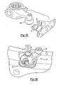
- Figure 3A shows details of the liner ring 51, and in particular a slot or track 68.
- An actuation structure 70 includes a bearing 172 which is to be received in the slot 68.
- the bearing 172 is associated with a drive having a spindle 76 driven by an actuator motor 78.
- a restrictor plate 74 seals off the mounting of the spindle in a fixed housing.
- a control for motor 78 receives feedback with regard to the condition of the engine, and can determine whether airflow is desired for cooling air at the inner periphery of the nozzle, and as actuation air to supplement the air acting on the sync ring.
- the control and motor 78 are shown schematically, however, it would preferably include a rotary motor, and a control for selectively driving the motor.
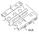
- Figure 3C shows features of the outer ring 58, and in particular a slot 64 which is associated with a lug 66 on the liner ring 51. While a single mating structure 64 and 66 is shown, there could be a plurality of such mating structures spaced around the periphery of the rings. Further, valve closures 62 extend forwardly from a forward face 63 of the outer ring 58. When the closures 62 are aligned with the openings 56 airflow is blocked. When the outer ring 58 is rotated, closures 62 are spaced from openings 56 such that the air can flow into the openings 56.
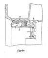
- Figure 4A shows a first position which may be considered a "hover" position for an associated aircraft. In this position, the temperature within the nozzle may not be as high as sometimes are experienced. As shown, the liner ring 51 has been rotated such that solid structure 70 is aligned with the openings 54. Now, cooling air will not be delivered to the interior of the nozzle. On the other hand, air can flow through openings 72, and around the outer ring 58, and reach the openings 56 in the housing 57. Figure 4B shows that the openings 54 are blocked while the openings 56 are open.
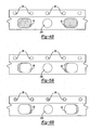
- Figure 5A shows another position, such as when an aircraft carrying the inventive gas turbine engine is under normal flying conditions.
- the liner ring 51 is rotated such that openings 52 are aligned with the openings 54, and cooling air is provided to the nozzle.
- the ring 58 is rotated to a position similar to that shown in Figure 4A such that air can also flow to the openings 56.
- Figure 5B shows that the openings 54 and 56 are both open.
- Figure 6A shows yet another position, wherein reduced airflow to the rear of the sync ring is necessary. As mentioned, such a position would typically occur at low speed and low altitude flying.
- the outer ring 58 is rotated such that the closures 62 block the openings 56.
- the openings 54 are opened.
- the openings 56 are blocked while the openings 54 are opened.
- a designer would be able to selectively form structure on the two rings such that these three positions can be easily achieved by simply rotating the liner ring a particular amount.
Abstract
Description
- This application relates to a control for air pressure supplied to assist an actuator in balancing forces on a linkage for controlling a nozzle cross-sectional area in a gas turbine engine.
- A gas turbine engine includes a fan section, a compression section, a combustion section and a turbine section. An axis of the engine is centrally disposed along the engine and extends longitudinally through the sections. A primary flow path for working medium gases extends axially through the sections of the engine.
- The nozzle for the gas turbine engine is typically provided with an actuation structure that can cause a plurality of flaps to pivot radially inwardly or outwardly to control the size of the nozzle opening. In the prior art, a hydraulic actuator drives a synchronous ring ("sync ring"), which is connected through linkages to the plurality of flaps. A control causes the actuator to move the flaps between various positions to provide a desired cross-sectional area.
- In the prior art, it is also known to supply air pressure to a rear face of the sync ring to assist in handling a load on the actuation structure. In part, this load is created since there is relatively high engine air pressure within the nozzle, and acting on an inner surface of the flaps, and relatively low ambient pressure on an outer surface of the flaps. The high pressure supplied to the rear face of the sync ring assists in carrying some of this load. However, at times, the ratio between the pressure within the nozzle and the ambient pressure is much lower. As an example, at low speed/low altitude applications the ratio is typically low. In such applications there may be too much air pressure supplied to the sync ring.
- Another feature which is often positioned adjacent the nozzle, is a liner ring which controls the flow of cooling air to the interior of the nozzle. The liner ring is rotated between a blocking position and an open position dependent on whether cooling air is necessary. Under certain conditions, such as when an aircraft is hovering, less cooling air is necessary. By blocking the flow of cooling air to the nozzle, additional cooling air is available for other purposes.
- In a disclosed embodiment of this invention, a liner ring as known in the art is rotated to control the flow of cooling air to the inner periphery of a nozzle in a gas turbine engine. When no cooling air is necessary, the liner ring is rotated by a motor to a position such that openings in the liner ring are not aligned with openings in a housing structure leading into the nozzle. In this position, the flow of cooling air will be blocked, and cooling air is available for other purposes in the gas turbine engine. On the other hand, during normal operation when cooling air is desired, the liner ring is rotated to a position such that the openings in the liner ring align with the openings in the housing and cooling air is delivered to the inner periphery of the nozzle. As mentioned, these features of the present invention are as known in the art.
- In one embodiment the liner ring is also constrained to rotate with an outer ring. The outer ring is biased axially relative to the liner ring such that an end surface of the outer ring abuts a valve plate in the housing. The valve plate has openings leading to the rear surface of an actuation structure for the flap. A motor and control can rotate the liner ring and thus, the outer ring between positions selectively allowing or blocking flow to the rear of the sync ring.
- By utilizing a single actuation structure, the additional feature of controlling the flow of air to the rear of the sync ring is achieved with the same motor which is already utilized to rotate the liner ring.
- These and other features of the present invention can be best understood from the following specification and drawings, the following of which is a brief description.
-
- Figure 1A schematically shows a gas turbine engine.
- Figure 1B shows a structure for moving a nozzle as known in the prior art.
- Figure 2 shows an inventive structure to supplement the Figure 1B structure.
- Figure 3A shows a first feature of an actuation structure.
- Figure 3B shows another view of the actuation structure.
- Figure 3C shows a view of the liner ring and the outer ring.
- Figure 4A shows a first operational position.
- Figure 4B shows another view of the first operational position.
- Figure 5A shows a second operational position.
- Figure 5B shows another view of the second operational position.
- Figure 6A shows a third operational position.
- Figure 6B shows another view of the third operational position.
- Figure 1A shows a
gas turbine engine 10. As known, afan section 11 moves air and rotates about anaxial center line 12. Acompressor section 13, a combustion section 14, and aturbine section 15 are also centered on theaxial center line 12. Anozzle section 16 of the turbine discharges gas downstream. Figure 1A is a highly schematic view, however, it does show the main components of the gas turbine engine. Further, while a particular type of gas turbine engine is illustrated in this figure, it should be understood that the present invention extends to other types of gas turbine engines. - As also shown in Figure 1A, a plurality of
flaps 31 at the end of thenozzle 16 can be pivoted radially inwardly or outwardly to control the cross-sectional area at the nozzle. This is as known in the art, and an actuation structure for pivoting theflaps 31 is shown in Figure 1B. As shown, ahydraulic actuator 41 drives async ring 44 through a connection at 46. Air pressure within thenozzle 40 acts on an inner surface of theflaps 31, while anambient pressure 42 outside theflaps 31 acts on an outer surface of theflaps 31. Typically, the air pressure at 40 is much greater than theambient air pressure 42. This high pressure imbalance creates forces on thesync ring 44 and linkages. Thus, pressurized air is delivered throughopenings 48 to a rear surface of thesync ring 44 to assist in handling the load. In this prior art structure, there is no control of the flow of this air. - Figure 2 shows a structure which supplements the Figure 1B actuation structure, and controls the flow of airflow into the rear surface of the
sync ring 44. As shown, anassembly 50 includes aliner ring 51 having a plurality ofopenings 52 which can be selectively aligned withopenings 54 to deliver cooling air into the inner periphery of the nozzle, and flaps 31. As shown, anouter ring 58 is positioned adjacent to theliner ring 51, and as will be explained, controls the flow of air flow throughopenings 56 to the rear surface of thesync ring 44 when less air flow is desired. - A
spring 60 biases theouter ring 58 against theopenings 56 in ahousing structure 57. - Figure 3A shows details of the
liner ring 51, and in particular a slot ortrack 68. Anactuation structure 70 includes abearing 172 which is to be received in theslot 68. - As shown in Figure 3B, the
bearing 172 is associated with a drive having aspindle 76 driven by anactuator motor 78. Arestrictor plate 74 seals off the mounting of the spindle in a fixed housing. A control formotor 78 receives feedback with regard to the condition of the engine, and can determine whether airflow is desired for cooling air at the inner periphery of the nozzle, and as actuation air to supplement the air acting on the sync ring. The control andmotor 78 are shown schematically, however, it would preferably include a rotary motor, and a control for selectively driving the motor. - Figure 3C shows features of the
outer ring 58, and in particular aslot 64 which is associated with alug 66 on theliner ring 51. While asingle mating structure valve closures 62 extend forwardly from aforward face 63 of theouter ring 58. When theclosures 62 are aligned with theopenings 56 airflow is blocked. When theouter ring 58 is rotated,closures 62 are spaced fromopenings 56 such that the air can flow into theopenings 56. - Figure 4A shows a first position which may be considered a "hover" position for an associated aircraft. In this position, the temperature within the nozzle may not be as high as sometimes are experienced. As shown, the
liner ring 51 has been rotated such thatsolid structure 70 is aligned with theopenings 54. Now, cooling air will not be delivered to the interior of the nozzle. On the other hand, air can flow throughopenings 72, and around theouter ring 58, and reach theopenings 56 in thehousing 57. Figure 4B shows that theopenings 54 are blocked while theopenings 56 are open. - Figure 5A shows another position, such as when an aircraft carrying the inventive gas turbine engine is under normal flying conditions. In this position, the
liner ring 51 is rotated such thatopenings 52 are aligned with theopenings 54, and cooling air is provided to the nozzle. Further, thering 58 is rotated to a position similar to that shown in Figure 4A such that air can also flow to theopenings 56. Figure 5B shows that theopenings - Figure 6A shows yet another position, wherein reduced airflow to the rear of the sync ring is necessary. As mentioned, such a position would typically occur at low speed and low altitude flying. In this position, the
outer ring 58 is rotated such that theclosures 62 block theopenings 56. At the same time, theopenings 54 are opened. Again, as shown in Figure 6B, theopenings 56 are blocked while theopenings 54 are opened. - As shown, in positions 4B, 5B and 6B,
other openings 200 ensure a minimum flow of cooling air regardless of whetheropenings 54 are opened or closed. - A designer would be able to selectively form structure on the two rings such that these three positions can be easily achieved by simply rotating the liner ring a particular amount.
- Although a preferred embodiment of this invention has been disclosed, a worker of ordinary skill in this art would recognize that certain modifications would come within the scope of this invention. For that reason, the following claims should be studied to determine the true scope and content of this invention.
Claims (10)
- A nozzle (16) for a gas turbine engine (10) comprising:a plurality of flaps (31) which may move to provide a desired cross-sectional area for a nozzle outlet;an actuator structure (41) for driving said flaps (31) through a linkage (46), said actuator structure (41) including at least one actuator member moving the flaps (31) through an intermediate structure (44);an air supply for supplying pressurized air to a rear surface of said intermediate structure (44), said pressurized air assisting said actuator structure (41) in holding said flap (31) at a desired position, and resisting a force from pressure (40) within said nozzle (16);a liner ring (51) for being rotated to control the flow of cooling air to an inner periphery of said nozzle (16), and a valve (58) for controlling flow of pressurized air to said rear surface of said intermediate structure (44), said valve (58) being controlled to reduce the flow of air when certain system conditions are sensed, said liner ring (51) moving with said valve (58).
- The nozzle (16) as set forth in Claim 1, wherein a pressure ratio between the air pressure within said nozzle (40), and an ambient pressure (42) is utilized to control said valve (58).
- The nozzle (16) as set forth in Claim 2, wherein the flow of pressurized air to said rear surface is reduced when said ratio is less than three.
- The nozzle (16) as set forth in any preceding claim, wherein said valve (58) is an outer ring which rotates with said liner ring (51), but is separate from said liner ring (51) such that it can move axially relative to said liner ring (51).
- The nozzle (16) as set forth in Claim 4, wherein a spring (60) is placed between surfaces on said outer ring (58) and said liner ring (51) and biases said outer ring (58) against a member with a plurality of ports (56) which are selectively opened or closed by said outer ring (58) to control the flow of air to said rear surface of said intermediate structure (44).
- The nozzle (16) as set forth in any preceding claim, wherein a rotating linkage (70) drives said liner ring (51) to rotate, said liner ring (51) having a plurality of spaced openings (52), said openings being selectively aligned with openings (54) in a fixed surface to allow or block the flow of cooling air into said nozzle (16).
- The nozzle (16) as set forth in Claim 6, wherein a bearing (172) on said rotating linkage (70) is received within a slot (68) in said liner ring (51).
- The nozzle (16) as set forth in any preceding claim, wherein said intermediate structure (44) is a sync ring defining a chamber for receiving pressurized air, and being connected to said actuator (41).
- A method of operating a nozzle (16) in a gas turbine engine (10) comprising the steps of:(1) providing a plurality of flaps (31) that may move to provide a desired cross-sectional area for a nozzle outlet, and providing an actuator structure (41) having at least one intermediate structure (44) that moves the flaps (31); and(2) rotating a rotatable structure (50) to control the flow of air flow to a rear surface of said intermediate structure (44), to either block or allow the flow of air to the intermediate structure (44) dependent on system conditions, and further rotating said rotatable structure (50) to control a flow of cooling air into an interior of said nozzle (16).
- The method as set forth in Claim 9, wherein said rotatable structure (50) includes a liner ring (51) controlling the flow of cooling air to the interior of the nozzle (16), and an outer ring (58) for controlling the flow of cooling air to the rear surface of the intermediate structure (44), said outer ring (58) being constrained to rotate with said liner ring (51).
Applications Claiming Priority (1)
| Application Number | Priority Date | Filing Date | Title |
|---|---|---|---|
| US11/588,884 US7854124B2 (en) | 2006-10-27 | 2006-10-27 | Combined control for supplying cooling air and support air in a turbine engine nozzle |
Publications (3)
| Publication Number | Publication Date |
|---|---|
| EP1918560A2 true EP1918560A2 (en) | 2008-05-07 |
| EP1918560A3 EP1918560A3 (en) | 2011-06-15 |
| EP1918560B1 EP1918560B1 (en) | 2013-02-13 |
Family
ID=38969846
Family Applications (1)
| Application Number | Title | Priority Date | Filing Date |
|---|---|---|---|
| EP07254244A Active EP1918560B1 (en) | 2006-10-27 | 2007-10-26 | Combined control for supplying cooling air and support air in a turbine engine nozzle |
Country Status (3)
| Country | Link |
|---|---|
| US (1) | US7854124B2 (en) |
| EP (1) | EP1918560B1 (en) |
| JP (1) | JP2008111434A (en) |
Families Citing this family (11)
| Publication number | Priority date | Publication date | Assignee | Title |
|---|---|---|---|---|
| US8015996B2 (en) * | 2005-04-28 | 2011-09-13 | United Technologies Corporation | Gas turbine engine air valve assembly |
| US7845176B2 (en) * | 2007-03-20 | 2010-12-07 | United Technologies Corporation | Mode strut and divergent flap interface |
| US8235345B2 (en) | 2008-04-30 | 2012-08-07 | United Technologies Corp. | Gas turbine engine systems and related methods involving thermally isolated retention |
| FR2933128B1 (en) * | 2008-06-25 | 2010-09-17 | Snecma | DEVICE FOR COLLECTING AIR IN A TURBOMACHINE |
| FR2933127B1 (en) * | 2008-06-25 | 2015-04-24 | Snecma | DEVICE FOR COLLECTING AIR IN A TURBOMACHINE |
| FR2937679B1 (en) * | 2008-10-24 | 2010-12-03 | Snecma | DEVICE FOR COLLECTING AIR IN A TURBOMACHINE |
| US9140213B2 (en) | 2011-12-06 | 2015-09-22 | United Technologies Corporation | Leaf spring damper for a turbine engine fuel delivery system |
| US9057455B2 (en) * | 2012-01-20 | 2015-06-16 | Hamilton Sundstrand Corporation | Crank |
| US9840984B2 (en) * | 2013-08-20 | 2017-12-12 | United Technologies Corporation | Linkage to control and restrain flap movement |
| PL421120A1 (en) | 2017-04-04 | 2018-10-08 | General Electric Company Polska Spolka Z Ograniczona Odpowiedzialnoscia | Turbine engine and component parts to be used in it |
| US11444507B2 (en) * | 2019-10-04 | 2022-09-13 | Hamilton Sundstrand Corporation | Actuation motor with cooling fins |
Citations (4)
| Publication number | Priority date | Publication date | Assignee | Title |
|---|---|---|---|---|
| US5209059A (en) * | 1991-12-27 | 1993-05-11 | The United States Of America As Represented By The Secretary Of The Air Force | Active cooling apparatus for afterburners |
| EP0833047A2 (en) * | 1996-09-27 | 1998-04-01 | United Technologies Corporation | Pressure balanced synchronizing nozzle |
| EP1156280A2 (en) * | 2000-05-15 | 2001-11-21 | United Technologies Corporation | Gas turbine engine liner |
| FR2860045A1 (en) * | 2003-09-24 | 2005-03-25 | Snecma Moteurs | Ducted-fan turbine engine for military application, has annular flow straightening chamber that is delimited at its downstream by conical ring, and piercing that is formed in leading wall and supplies cooling air to chamber |
Family Cites Families (12)
| Publication number | Priority date | Publication date | Assignee | Title |
|---|---|---|---|---|
| US4440347A (en) * | 1981-12-28 | 1984-04-03 | United Technologies Corporation | Simplified means for balancing the loads on a variable area nozzle |
| US4440346A (en) * | 1981-12-28 | 1984-04-03 | United Technologies Corporation | Axially translatable variable area convergent/divergent nozzle |
| US4447009A (en) * | 1981-12-28 | 1984-05-08 | United Technologies Corporation | Three-dimensional axially translatable convergent/divergent nozzle assembly |
| US4420932A (en) * | 1982-03-02 | 1983-12-20 | The United States Of America As Represented By The Secretary Of The Air Force | Pressure control system for convergent-divergent exhaust nozzle |
| US5150839A (en) * | 1991-03-14 | 1992-09-29 | General Electric Company | Nozzle load management |
| US5833139A (en) * | 1995-09-06 | 1998-11-10 | United Technologies Corporation | Single variable flap exhaust nozzle |
| US5797544A (en) * | 1996-09-27 | 1998-08-25 | United Technologies Corporation | C/D nozzle with synchronizing ring link suspension |
| US5813611A (en) | 1996-09-27 | 1998-09-29 | United Technologies Corporation | Compact pressure balanced fulcrum-link nozzle |
| US6021637A (en) * | 1997-09-29 | 2000-02-08 | General Electric Company | Integrated fluidic CD nozzle for gas turbine engine |
| US6694723B2 (en) * | 2002-03-27 | 2004-02-24 | United Technologies Corporation | Valve assembly for gas turbine engine |
| US7225622B2 (en) | 2003-07-21 | 2007-06-05 | United Technologies Corporation | Turbine engine nozzle |
| US7581382B2 (en) * | 2005-04-28 | 2009-09-01 | United Technologies Corporation | Gas turbine engine air valve assembly |
-
2006
- 2006-10-27 US US11/588,884 patent/US7854124B2/en active Active
-
2007
- 2007-10-19 JP JP2007271939A patent/JP2008111434A/en active Pending
- 2007-10-26 EP EP07254244A patent/EP1918560B1/en active Active
Patent Citations (4)
| Publication number | Priority date | Publication date | Assignee | Title |
|---|---|---|---|---|
| US5209059A (en) * | 1991-12-27 | 1993-05-11 | The United States Of America As Represented By The Secretary Of The Air Force | Active cooling apparatus for afterburners |
| EP0833047A2 (en) * | 1996-09-27 | 1998-04-01 | United Technologies Corporation | Pressure balanced synchronizing nozzle |
| EP1156280A2 (en) * | 2000-05-15 | 2001-11-21 | United Technologies Corporation | Gas turbine engine liner |
| FR2860045A1 (en) * | 2003-09-24 | 2005-03-25 | Snecma Moteurs | Ducted-fan turbine engine for military application, has annular flow straightening chamber that is delimited at its downstream by conical ring, and piercing that is formed in leading wall and supplies cooling air to chamber |
Also Published As
| Publication number | Publication date |
|---|---|
| EP1918560B1 (en) | 2013-02-13 |
| US7854124B2 (en) | 2010-12-21 |
| JP2008111434A (en) | 2008-05-15 |
| US20080098742A1 (en) | 2008-05-01 |
| EP1918560A3 (en) | 2011-06-15 |
Similar Documents
| Publication | Publication Date | Title |
|---|---|---|
| EP1918560B1 (en) | Combined control for supplying cooling air and support air in a turbine engine nozzle | |
| EP1472446B1 (en) | Actuator for an air turbine starter valve | |
| EP2384400B1 (en) | Variable pressure ratio compressor | |
| US6684898B2 (en) | Dual actuator air turbine starter valve | |
| EP2066890B1 (en) | Modulating flow through gas turbine engine cooling system | |
| EP1749253B1 (en) | Pneumatic valve control having improved opening characteristics and an air turbine starter incorporating the same | |
| EP3626942B1 (en) | Ducted gas turbine engine stability bleed valve with passive and active shutoff | |
| EP1939437B1 (en) | Turbine engine with modulated flow fan and method of operation | |
| US20070234738A1 (en) | Self-actuating bleed valve for gas turbine engine | |
| US11873771B2 (en) | Propeller assembly and pitch control unit | |
| US11162458B2 (en) | Ventilation and extinguishing device for a gas turbine engine | |
| EP2074316B1 (en) | Managing low pressure turbine maximum speed in a turbofan engine | |
| EP2932068B1 (en) | Gas turbine engine with cooling scheme for drive gear system and pitch control | |
| EP2960468B1 (en) | Geared turbofan engine with low pressure environmental control system for aircraft | |
| EP2395222B1 (en) | Gas turbine engine system and corresponding controlling method | |
| EP1870332A1 (en) | Decoupled ducting for twin-engine reaction rotor drive | |
| EP1302640B1 (en) | Variable cycle boost propulsor | |
| EP1908950B1 (en) | Pressure balance control for gas turbine engine nozzle | |
| EP1722071B1 (en) | Gas turbine engine air valve assembly and a method for reengineering an engine configuration | |
| EP3636896A1 (en) | A controller assembly | |
| EP2074310B1 (en) | Controlling the aerodynamic drag of a gas turbine engine during a shutdown state | |
| EP3842627B1 (en) | Air turbine starter air valve |
Legal Events
| Date | Code | Title | Description |
|---|---|---|---|
| PUAI | Public reference made under article 153(3) epc to a published international application that has entered the european phase |
Free format text: ORIGINAL CODE: 0009012 |
|
| AK | Designated contracting states |
Kind code of ref document: A2 Designated state(s): AT BE BG CH CY CZ DE DK EE ES FI FR GB GR HU IE IS IT LI LT LU LV MC MT NL PL PT RO SE SI SK TR |
|
| AX | Request for extension of the european patent |
Extension state: AL BA HR MK RS |
|
| PUAL | Search report despatched |
Free format text: ORIGINAL CODE: 0009013 |
|
| AK | Designated contracting states |
Kind code of ref document: A3 Designated state(s): AT BE BG CH CY CZ DE DK EE ES FI FR GB GR HU IE IS IT LI LT LU LV MC MT NL PL PT RO SE SI SK TR |
|
| AX | Request for extension of the european patent |
Extension state: AL BA HR MK RS |
|
| 17P | Request for examination filed |
Effective date: 20111215 |
|
| AKX | Designation fees paid |
Designated state(s): DE FR GB |
|
| GRAP | Despatch of communication of intention to grant a patent |
Free format text: ORIGINAL CODE: EPIDOSNIGR1 |
|
| GRAS | Grant fee paid |
Free format text: ORIGINAL CODE: EPIDOSNIGR3 |
|
| GRAA | (expected) grant |
Free format text: ORIGINAL CODE: 0009210 |
|
| AK | Designated contracting states |
Kind code of ref document: B1 Designated state(s): DE FR GB |
|
| REG | Reference to a national code |
Ref country code: GB Ref legal event code: FG4D |
|
| REG | Reference to a national code |
Ref country code: DE Ref legal event code: R096 Ref document number: 602007028392 Country of ref document: DE Effective date: 20130411 |
|
| PLBE | No opposition filed within time limit |
Free format text: ORIGINAL CODE: 0009261 |
|
| STAA | Information on the status of an ep patent application or granted ep patent |
Free format text: STATUS: NO OPPOSITION FILED WITHIN TIME LIMIT |
|
| 26N | No opposition filed |
Effective date: 20131114 |
|
| REG | Reference to a national code |
Ref country code: DE Ref legal event code: R097 Ref document number: 602007028392 Country of ref document: DE Effective date: 20131114 |
|
| REG | Reference to a national code |
Ref country code: FR Ref legal event code: ST Effective date: 20140630 |
|
| PG25 | Lapsed in a contracting state [announced via postgrant information from national office to epo] |
Ref country code: FR Free format text: LAPSE BECAUSE OF NON-PAYMENT OF DUE FEES Effective date: 20131031 |
|
| REG | Reference to a national code |
Ref country code: DE Ref legal event code: R082 Ref document number: 602007028392 Country of ref document: DE Representative=s name: SCHMITT-NILSON SCHRAUD WAIBEL WOHLFROM PATENTA, DE |
|
| REG | Reference to a national code |
Ref country code: DE Ref legal event code: R082 Ref document number: 602007028392 Country of ref document: DE Representative=s name: SCHMITT-NILSON SCHRAUD WAIBEL WOHLFROM PATENTA, DE Ref country code: DE Ref legal event code: R081 Ref document number: 602007028392 Country of ref document: DE Owner name: UNITED TECHNOLOGIES CORP. (N.D.GES.D. STAATES , US Free format text: FORMER OWNER: UNITED TECHNOLOGIES CORPORATION, EAST HARTFORD, CONN., US |
|
| REG | Reference to a national code |
Ref country code: DE Ref legal event code: R081 Ref document number: 602007028392 Country of ref document: DE Owner name: RAYTHEON TECHNOLOGIES CORPORATION (N.D.GES.D.S, US Free format text: FORMER OWNER: UNITED TECHNOLOGIES CORP. (N.D.GES.D. STAATES DELAWARE), FARMINGTON, CONN., US |
|
| P01 | Opt-out of the competence of the unified patent court (upc) registered |
Effective date: 20230519 |
|
| PGFP | Annual fee paid to national office [announced via postgrant information from national office to epo] |
Ref country code: GB Payment date: 20230920 Year of fee payment: 17 |
|
| PGFP | Annual fee paid to national office [announced via postgrant information from national office to epo] |
Ref country code: DE Payment date: 20230920 Year of fee payment: 17 |