JP2008111434A - Gas turbine engine nozzle and method for operating gas turbine engine nozzle - Google Patents
Gas turbine engine nozzle and method for operating gas turbine engine nozzle Download PDFInfo
- Publication number
- JP2008111434A JP2008111434A JP2007271939A JP2007271939A JP2008111434A JP 2008111434 A JP2008111434 A JP 2008111434A JP 2007271939 A JP2007271939 A JP 2007271939A JP 2007271939 A JP2007271939 A JP 2007271939A JP 2008111434 A JP2008111434 A JP 2008111434A
- Authority
- JP
- Japan
- Prior art keywords
- nozzle
- ring
- air
- flow
- liner ring
- Prior art date
- Legal status (The legal status is an assumption and is not a legal conclusion. Google has not performed a legal analysis and makes no representation as to the accuracy of the status listed.)
- Pending
Links
Images


Classifications
-
- F—MECHANICAL ENGINEERING; LIGHTING; HEATING; WEAPONS; BLASTING
- F02—COMBUSTION ENGINES; HOT-GAS OR COMBUSTION-PRODUCT ENGINE PLANTS
- F02K—JET-PROPULSION PLANTS
- F02K1/00—Plants characterised by the form or arrangement of the jet pipe or nozzle; Jet pipes or nozzles peculiar thereto
- F02K1/78—Other construction of jet pipes
- F02K1/82—Jet pipe walls, e.g. liners
-
- F—MECHANICAL ENGINEERING; LIGHTING; HEATING; WEAPONS; BLASTING
- F02—COMBUSTION ENGINES; HOT-GAS OR COMBUSTION-PRODUCT ENGINE PLANTS
- F02K—JET-PROPULSION PLANTS
- F02K1/00—Plants characterised by the form or arrangement of the jet pipe or nozzle; Jet pipes or nozzles peculiar thereto
- F02K1/06—Varying effective area of jet pipe or nozzle
- F02K1/12—Varying effective area of jet pipe or nozzle by means of pivoted flaps
Abstract
Description
本発明は、アクチュエータがガスタービンエンジンのノズル断面積を制御するリンク機構に作用する力のバランスを保つのを補助するために供給される空気圧を制御する制御装置に関する。 The present invention relates to a control device that controls the air pressure supplied to assist an actuator in maintaining a balance of forces acting on a link mechanism that controls the nozzle cross-sectional area of a gas turbine engine.
ガスタービンエンジンは、ファンセクション、圧縮セクション、燃焼セクション、およびタービンセクションを備える。エンジンの軸は、エンジンに沿って中心に位置し、各セクションを通って長手方向に延びる。作動媒体ガス用の主流路が、エンジンの各セクションを軸方向に貫通している。 The gas turbine engine includes a fan section, a compression section, a combustion section, and a turbine section. The engine shaft is centrally located along the engine and extends longitudinally through each section. A main flow path for working medium gas extends axially through each section of the engine.
ガスタービンエンジン用のノズルは、典型的には、ノズル開口の大きさを制御するために複数のフラップを半径方向内方または外方に枢動させる作動構造を備える。先行技術では、流体アクチュエータが、同期リングを駆動し、この同期リングは、リンク機構を介して、複数のフラップに連結されている。所望の断面積をもたらすために、制御装置が、アクチュエータによってフラップを種々の位置の間で移動させる。 Nozzles for gas turbine engines typically include an actuation structure that pivots a plurality of flaps radially inward or outward to control the size of the nozzle opening. In the prior art, a fluid actuator drives a synchronization ring, which is connected to a plurality of flaps via a linkage. In order to provide the desired cross-sectional area, the controller moves the flap between various positions by means of an actuator.
作動構造への負荷に対抗するのを補助するために、空気圧を同期リングの後面に供給することも、先行技術として知られている。この負荷の一部は、比較的高い空気圧がノズル内でフラップの内面に作用し、比較的低い外気圧がフラップの外面に作用することによって、生じる。同期リングの後面に供給される高圧は、この負荷の一部を支持するように働く。しかし、時には、ノズル内の圧力と外気圧との比率が極めて小さいことがある。一例として、低速/低高度の運転時では、通常、この比率が低い。このような運転時には、同期リングに作用する空気圧が高すぎる場合がある。 It is also known in the prior art to supply air pressure to the rear face of the synchronization ring to help counteract loads on the operating structure. Part of this load is caused by the relatively high air pressure acting on the inner surface of the flap in the nozzle and the relatively low external air pressure acting on the outer surface of the flap. The high pressure supplied to the rear face of the synchronization ring serves to support part of this load. However, sometimes the ratio between the pressure inside the nozzle and the outside air pressure is very small. As an example, this ratio is usually low during low / low altitude driving. During such operation, the air pressure acting on the synchronization ring may be too high.
ノズルに隣接して配置されることが多い他の特徴部は、ノズルの内部への冷却空気の流れを制御するライナリングである。ライナリングは、冷却空気が必要であるかどうかによって、閉位置と開位置との間で回転する。条件によっては、例えば、航空機がホバリングしているときは、必要な冷却空気が比較的少ない。この場合、ノズルへの冷却空気の流れを阻止することによって、付加的な冷却空気が他の目的に利用可能となる。 Another feature often placed adjacent to the nozzle is a liner ring that controls the flow of cooling air into the interior of the nozzle. The liner ring rotates between a closed position and an open position depending on whether cooling air is required. Depending on conditions, for example, when the aircraft is hovering, relatively little cooling air is required. In this case, additional cooling air is available for other purposes by blocking the flow of cooling air to the nozzle.
本発明は、アクチュエータがガスタービンエンジンのノズル断面積を制御するリンク機構に作用する力のバランスを保つのを補助するために供給される空気圧を制御する制御装置を提供する。 The present invention provides a control device that controls the air pressure supplied to help the actuator balance the forces acting on the linkage that controls the nozzle cross-sectional area of the gas turbine engine.
本発明の開示される実施形態では、当技術分野において周知のライナリングは、ガスタービンのノズルの内周への冷却空気の流れを制御するように、回転される。冷却空気が必要でないとき、ライナリングは、モータによって、ライナリングの開口がノズル内に通じるハウジング構造の開口と整列しない位置に、回転される。この位置では、冷却空気の流れが阻止され、冷却空気は、ガスタービンエンジン内において他の目的に利用される。一方、冷却空気が望まれる通常の運転中、ライナリングは、ライナリングの開口がハウジングの開口と整列する位置に回転され、冷却空気は、ノズルの内周に送給される。前述したように、本発明のこれらの特徴は、当技術分野において、すでに知られている。 In the disclosed embodiment of the present invention, a liner ring, well known in the art, is rotated to control the flow of cooling air to the inner periphery of the gas turbine nozzle. When cooling air is not required, the liner ring is rotated by the motor to a position where the opening in the liner ring is not aligned with the opening in the housing structure leading into the nozzle. In this position, the flow of cooling air is blocked and the cooling air is used for other purposes within the gas turbine engine. On the other hand, during normal operation where cooling air is desired, the liner ring is rotated to a position where the opening in the liner ring is aligned with the opening in the housing, and the cooling air is delivered to the inner periphery of the nozzle. As mentioned above, these features of the present invention are already known in the art.
また、ライナリングは、外側リングと共に回転するように、拘束されている。外側リングは、その端面がハウジングの弁板と当接するように、ライナリングに対して軸方向に付勢されている。この弁板は、フラップ用の作動構造の後面に通じる開口を有する。モータおよび制御装置によって、ライナリング、従って、外側リングを、同期リングの後面への流れを選択的に許容する位置または選択的に阻止する位置間で、回転させることができる。 Also, the liner ring is constrained to rotate with the outer ring. The outer ring is urged in the axial direction with respect to the liner ring so that the end face thereof is in contact with the valve plate of the housing. This valve plate has an opening leading to the rear surface of the flap actuating structure. By means of the motor and the controller, the liner ring, and thus the outer ring, can be rotated between a position that selectively allows or selectively blocks flow to the rear face of the synchronization ring.
単一の作動構造を利用することによって、同期リングの後面への空気の流れを制御する付加的な特徴部は、ライナリングを回転させるのにすでに利用されているのと同じモータによって、実現される。 By utilizing a single actuation structure, the additional features that control the flow of air to the rear face of the synchronization ring are realized by the same motor already utilized to rotate the liner ring. The
本発明のこれらおよび他の特徴は、以下の詳細な説明および後で簡単に説明する図面から最もよく理解されるだろう。 These and other features of the present invention will be best understood from the following detailed description and the drawings briefly described below.
図1Aは、ガスタービンエンジン10を示している。周知のように、ファンセクション11は、空気を動かし、軸方向中心線12を中心として回転する。圧縮機セクション13、燃焼セクション14、およびタービンセクション15も、軸方向中心線12を中心に配置されている。タービンのノズルセクション16は、ガスを下流に排出する。図1Aは、極めて概略的な図であるが、ガスタービンエンジンの主な構成要素を示している。なお、特定の形式のガスタービンエンジンがこの図には示されているが、本発明は、他の形式のガスタービンエンジンにも及ぶことが理解されるべきである。
FIG. 1A shows a
図1Aにも示されるように、ノズル16の端部の複数のフラップ31は、ノズルの断面積を制御するために、半径方向内方または半径方向外方に枢動される。これは、当技術分野において周知であり、フラップ31を枢動させる作動構造が、図1Bに示されている。図示されるように、流体アクチュエータ41が、連結部46を介して、同期リング44を駆動する。ノズル内の空気圧40がフラップ31の内面に作用すると共に、フラップ31の外部の外気圧42がフラップ31の外面に作用する。通常、空気圧40は、外気圧よりも著しく高い。この高い圧力不均衡によって、同期リング44およびリンク機構に作用する力が生じる。従って、この負荷に対抗するのを補助するために、加圧空気が、開口48を通って、同期リング44の後面に送給される。この先行技術の構造では、この空気の流れは制御されない。
As also shown in FIG. 1A, the plurality of
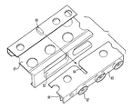
図2は、図1Bの作動構造を補足し、同期リング44の後面への空気流れを制御する構造を示している。図示されるように、アッセンブリ50は、複数の開口52を有するライナリング51を備える。これらの開口52を、冷却空気をノズルの内周およびフラップ31に送給するために、選択的に開口54と整列させることができる。図示されるように、外側リング58は、ライナリング51に隣接して配置され、後述するように、所望の空気流れが比較的少ないとき、開口56を通って同期リング44の後面に向かう空気流れを制御する。
FIG. 2 supplements the operating structure of FIG. 1B and shows a structure for controlling the air flow to the rear surface of the
バネ60が、外側リング58をハウジング構造57の開口56に付勢している。
A
図3Aは、ライナリング51の詳細、特に、スロットまたはトラック68を示している。作動構造70は、スロット68内に収容される軸受172を備える。
FIG. 3A shows details of the
図3Bに示されるように、軸受172は、アクチュエータモータ78によって駆動されるスピンドル76を有する駆動装置と関連している。制流プレート74が、固定ハウジングへのスピンドルの取付けを密封する。モータ78用の制御装置が、エンジンの状態に関して、フィードバックデータを受信し、空気流れがノズルの内周への冷却空気として望まれているかどうか、および空気流れが同期リングに作用する空気を補足する作動空気として望まれているかどうかを決定する。制御装置およびモータ78は、概略的に示されているが、モータ78は、回転式であると好ましく、制御装置は、そのモータを選択的に制御する形式であると好ましい。
As shown in FIG. 3B, the
図3Cは、外側リング58、特にライナリング51のラグ66と関連するスロット64を示している。単一の嵌合構造64,66が示されているが、リングの周りに離間して配置される複数のこのような嵌合構造があってもよい。さらに、弁閉鎖体62が、外側リング58の前面63から前方に延びている。これらの閉鎖体62が開口56と整列すると、空気流れが阻止される。外側リング58が回転すると、閉鎖体62が開口56から離間し、これによって、空気が開口56内に流れる。
FIG. 3C shows the
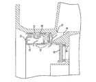
図4Aは、関連する航空機用の「ホバリング」位置とみなすことができる第1の位置を示している。この位置では、ノズル内の温度は、他の状態で経験されるほど高くない場合がある。図示されるように、ライナリング51は、中実構造70が開口54と整列するように回転されている。この場合、冷却空気は、ノズルの内部に送給されない。一方、空気は、開口72内および外側リングの周囲に流れ、ハウジング57の開口56に達する。図4Bは、開口54が塞がれると共に、開口56が開いた状態を示している。
FIG. 4A shows a first position that can be considered a “hovering” position for the associated aircraft. In this position, the temperature in the nozzle may not be as high as is experienced in other conditions. As shown, the
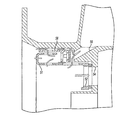
図5Aは、他の位置、例えば、本発明のタービンエンジンを有する航空機が通常の飛行状態にあるときを示している。この位置では、ライナリング51は、開口52が開口54と整列するように、回転され、冷却空気が、ノズルに供給される。さらに、外側リング58が、図4Aに示されるのと同様の位置に回転され、これによって、空気が開口56にも流れる。図5Bは、開口54,56の両方が開いた状態を示している。
FIG. 5A shows another position, for example when an aircraft having the turbine engine of the present invention is in normal flight. In this position, the
図6Aは、同期リングの後面への空気流れを減少させる必要があるさらに他の位置を示している。前述したように、このような位置は、典型的には、低速度および低高度の飛行時に生じる。この位置では、外側リング58は、閉鎖体62が開口56を塞ぐように、回転される。同時に、開口54が開かれる。ここでも、図6Bに示されるように、開口56が塞がれると共に、開口54が開かれる。
FIG. 6A shows yet another position where the air flow to the back of the synchronization ring needs to be reduced. As previously mentioned, such positions typically occur during low speed and low altitude flights. In this position, the
図示されるように、図4B,5B,6Bに示される位置では、他の開口200によって、開口54の開閉とは無関係に、最小限の冷却空気が確保される。
As shown in the figure, at the positions shown in FIGS. 4B, 5B, and 6B, a minimum amount of cooling air is secured by the
設計者であれば、ライナリングを特定量だけ単純に回転させることによって、これらの3つの位置が容易に得られるように、2つのリング構造を選択的に形成することができるだろう。 A designer could selectively form two ring structures so that these three positions are easily obtained by simply rotating the liner ring by a certain amount.
本発明の好ましい実施形態について、開示した。より簡素化された装置が、「ガスタービンエンジンノズル用の圧力バランスの制御」と題する同時係属中の米国特許出願第11/527,188号に開示されている。 A preferred embodiment of the present invention has been disclosed. A more simplified apparatus is disclosed in copending US patent application Ser. No. 11 / 527,188 entitled “Controlling Pressure Balance for Gas Turbine Engine Nozzles”.
本発明の好ましい実施形態を開示したが、当業者であれば、いくつかの修正が本発明の範囲内においてなされ得ることを認めるだろう。この理由から、本発明の真の範囲および内容を決定するには、特許請求の範囲が検討されるべきである。 While preferred embodiments of the invention have been disclosed, those skilled in the art will recognize that several modifications can be made within the scope of the invention. For this reason, the following claims should be studied to determine the true scope and content of this invention.
Claims (10)
ノズル出口に所望の断面積をもたらすように移動可能な複数のフラップと、
前記フラップをリンク機構を介して駆動するアクチュエータ構造であって、前記フラップを中間部材を介して移動させる少なくとも1つのアクチュエータ部材を備える、アクチュエータ構造と、
前記中間部材の後面に加圧空気を供給する空気源であって、前記アクチュエータ部材が前記フラップを所望位置に保持し、前記ノズル内の圧力による力に対抗するのを補助する、空気源と、
前記ノズルの内周への冷却空気の流れを制御するように回転するライナリング、および前記中間部材の前記後面への加圧空気の流れを制御する弁であって、前記弁が、所定のシステム状態が検知されたとき、空気の流れを減少させるように制御され、前記ライナリングが、前記弁と共に移動する、ライナリングおよび弁と、
を備えることを特徴とするノズル。 A nozzle for a gas turbine engine,
A plurality of flaps movable to provide a desired cross-sectional area at the nozzle outlet;
An actuator structure for driving the flap via a link mechanism, the actuator structure comprising at least one actuator member for moving the flap via an intermediate member;
An air source for supplying pressurized air to a rear surface of the intermediate member, the air source assisting the actuator member to hold the flap in a desired position and to counter the force due to pressure in the nozzle;
A liner ring that rotates to control the flow of cooling air to the inner periphery of the nozzle, and a valve that controls the flow of pressurized air to the rear surface of the intermediate member, the valve being a predetermined system A liner ring and a valve that are controlled to reduce air flow when a condition is detected, and wherein the liner ring moves with the valve;
A nozzle comprising:
(1)ノズル出口に所望の断面積をもたらすように移動可能である複数のフラップを設けると共に、前記フラップを移動させる少なくとも1つの中間部材を有するアクチュエータ構造を設けるステップと、
(2)システム状態に応じて、前記中間部材への空気の流れを阻止するかまたは許容するために、前記中間部材の後面への空気流れを制御する回転可能な構造を回転させ、さらに、前記ノズルの内部への冷却空気の流れを制御するために、前記回転可能な構造を回転させるステップと、
を含むことを特徴とする方法。 A method for operating a nozzle of a gas turbine engine, comprising:
(1) providing a plurality of flaps movable to provide a desired cross-sectional area at the nozzle outlet, and providing an actuator structure having at least one intermediate member for moving the flaps;
(2) Rotating a rotatable structure that controls the air flow to the rear surface of the intermediate member to block or allow air flow to the intermediate member, depending on system conditions; Rotating the rotatable structure to control the flow of cooling air into the interior of the nozzle;
A method comprising the steps of:
Applications Claiming Priority (1)
| Application Number | Priority Date | Filing Date | Title |
|---|---|---|---|
| US11/588,884 US7854124B2 (en) | 2006-10-27 | 2006-10-27 | Combined control for supplying cooling air and support air in a turbine engine nozzle |
Publications (1)
| Publication Number | Publication Date |
|---|---|
| JP2008111434A true JP2008111434A (en) | 2008-05-15 |
Family
ID=38969846
Family Applications (1)
| Application Number | Title | Priority Date | Filing Date |
|---|---|---|---|
| JP2007271939A Pending JP2008111434A (en) | 2006-10-27 | 2007-10-19 | Gas turbine engine nozzle and method for operating gas turbine engine nozzle |
Country Status (3)
| Country | Link |
|---|---|
| US (1) | US7854124B2 (en) |
| EP (1) | EP1918560B1 (en) |
| JP (1) | JP2008111434A (en) |
Families Citing this family (11)
| Publication number | Priority date | Publication date | Assignee | Title |
|---|---|---|---|---|
| US8015996B2 (en) * | 2005-04-28 | 2011-09-13 | United Technologies Corporation | Gas turbine engine air valve assembly |
| US7845176B2 (en) * | 2007-03-20 | 2010-12-07 | United Technologies Corporation | Mode strut and divergent flap interface |
| US8235345B2 (en) | 2008-04-30 | 2012-08-07 | United Technologies Corp. | Gas turbine engine systems and related methods involving thermally isolated retention |
| FR2933128B1 (en) * | 2008-06-25 | 2010-09-17 | Snecma | DEVICE FOR COLLECTING AIR IN A TURBOMACHINE |
| FR2933127B1 (en) * | 2008-06-25 | 2015-04-24 | Snecma | DEVICE FOR COLLECTING AIR IN A TURBOMACHINE |
| FR2937679B1 (en) * | 2008-10-24 | 2010-12-03 | Snecma | DEVICE FOR COLLECTING AIR IN A TURBOMACHINE |
| US9140213B2 (en) | 2011-12-06 | 2015-09-22 | United Technologies Corporation | Leaf spring damper for a turbine engine fuel delivery system |
| US9057455B2 (en) * | 2012-01-20 | 2015-06-16 | Hamilton Sundstrand Corporation | Crank |
| US9840984B2 (en) * | 2013-08-20 | 2017-12-12 | United Technologies Corporation | Linkage to control and restrain flap movement |
| PL421120A1 (en) | 2017-04-04 | 2018-10-08 | General Electric Company Polska Spolka Z Ograniczona Odpowiedzialnoscia | Turbine engine and component parts to be used in it |
| US11444507B2 (en) * | 2019-10-04 | 2022-09-13 | Hamilton Sundstrand Corporation | Actuation motor with cooling fins |
Citations (6)
| Publication number | Priority date | Publication date | Assignee | Title |
|---|---|---|---|---|
| JPH10103153A (en) * | 1996-09-27 | 1998-04-21 | United Technol Corp <Utc> | Toward-end thinning/thickening exhaust nozzle for gas turbine engine power device supplying power to aircraft |
| US5797544A (en) * | 1996-09-27 | 1998-08-25 | United Technologies Corporation | C/D nozzle with synchronizing ring link suspension |
| US5833139A (en) * | 1995-09-06 | 1998-11-10 | United Technologies Corporation | Single variable flap exhaust nozzle |
| US6021637A (en) * | 1997-09-29 | 2000-02-08 | General Electric Company | Integrated fluidic CD nozzle for gas turbine engine |
| JP2005042719A (en) * | 2003-07-21 | 2005-02-17 | United Technol Corp <Utc> | Turbine engine nozzle sub-assembly and manufacturing method therefor |
| US20050091964A1 (en) * | 2003-09-24 | 2005-05-05 | Snecma Moteurs | Ventilation system for a convergent divergent exhaust nozzle |
Family Cites Families (10)
| Publication number | Priority date | Publication date | Assignee | Title |
|---|---|---|---|---|
| US4440346A (en) * | 1981-12-28 | 1984-04-03 | United Technologies Corporation | Axially translatable variable area convergent/divergent nozzle |
| US4440347A (en) * | 1981-12-28 | 1984-04-03 | United Technologies Corporation | Simplified means for balancing the loads on a variable area nozzle |
| US4447009A (en) * | 1981-12-28 | 1984-05-08 | United Technologies Corporation | Three-dimensional axially translatable convergent/divergent nozzle assembly |
| US4420932A (en) * | 1982-03-02 | 1983-12-20 | The United States Of America As Represented By The Secretary Of The Air Force | Pressure control system for convergent-divergent exhaust nozzle |
| US5150839A (en) * | 1991-03-14 | 1992-09-29 | General Electric Company | Nozzle load management |
| US5209059A (en) * | 1991-12-27 | 1993-05-11 | The United States Of America As Represented By The Secretary Of The Air Force | Active cooling apparatus for afterburners |
| US5794850A (en) * | 1996-09-27 | 1998-08-18 | United Technologies Corporation | Enclosed pressure balanced sync ring nozzle |
| US6418709B1 (en) * | 2000-05-15 | 2002-07-16 | United Technologies Corporation | Gas turbine engine liner |
| US6694723B2 (en) * | 2002-03-27 | 2004-02-24 | United Technologies Corporation | Valve assembly for gas turbine engine |
| US7581382B2 (en) * | 2005-04-28 | 2009-09-01 | United Technologies Corporation | Gas turbine engine air valve assembly |
-
2006
- 2006-10-27 US US11/588,884 patent/US7854124B2/en active Active
-
2007
- 2007-10-19 JP JP2007271939A patent/JP2008111434A/en active Pending
- 2007-10-26 EP EP07254244A patent/EP1918560B1/en active Active
Patent Citations (6)
| Publication number | Priority date | Publication date | Assignee | Title |
|---|---|---|---|---|
| US5833139A (en) * | 1995-09-06 | 1998-11-10 | United Technologies Corporation | Single variable flap exhaust nozzle |
| JPH10103153A (en) * | 1996-09-27 | 1998-04-21 | United Technol Corp <Utc> | Toward-end thinning/thickening exhaust nozzle for gas turbine engine power device supplying power to aircraft |
| US5797544A (en) * | 1996-09-27 | 1998-08-25 | United Technologies Corporation | C/D nozzle with synchronizing ring link suspension |
| US6021637A (en) * | 1997-09-29 | 2000-02-08 | General Electric Company | Integrated fluidic CD nozzle for gas turbine engine |
| JP2005042719A (en) * | 2003-07-21 | 2005-02-17 | United Technol Corp <Utc> | Turbine engine nozzle sub-assembly and manufacturing method therefor |
| US20050091964A1 (en) * | 2003-09-24 | 2005-05-05 | Snecma Moteurs | Ventilation system for a convergent divergent exhaust nozzle |
Also Published As
| Publication number | Publication date |
|---|---|
| EP1918560A2 (en) | 2008-05-07 |
| US7854124B2 (en) | 2010-12-21 |
| EP1918560A3 (en) | 2011-06-15 |
| US20080098742A1 (en) | 2008-05-01 |
| EP1918560B1 (en) | 2013-02-13 |
Similar Documents
| Publication | Publication Date | Title |
|---|---|---|
| JP2008111434A (en) | Gas turbine engine nozzle and method for operating gas turbine engine nozzle | |
| US8092153B2 (en) | Bypass air scoop for gas turbine engine | |
| US6684898B2 (en) | Dual actuator air turbine starter valve | |
| US8863529B2 (en) | Variable pressure ratio compressor | |
| EP1472446B1 (en) | Actuator for an air turbine starter valve | |
| EP1749253B1 (en) | Pneumatic valve control having improved opening characteristics and an air turbine starter incorporating the same | |
| US11208913B2 (en) | Gas turbine engine having minimum cooling airflow | |
| JP4884102B2 (en) | Valve assembly for a gas turbine engine | |
| EP3318726B1 (en) | System and method for controlling dual starter air valve | |
| JP2006161814A (en) | Gas turbine engine and its oil system | |
| JP2009002329A (en) | Turbine engine and method for regulating bearing load in turbine engine | |
| US6910851B2 (en) | Turbofan jet engine having a turbine case cooling valve | |
| US20170114657A1 (en) | Bleed valve arrangement | |
| JP2004169703A (en) | Variable form turbine | |
| KR20060113380A (en) | Gas turbine engine air valve assembly | |
| US9217390B2 (en) | Thrust reverser maintenance actuation system | |
| US9988927B2 (en) | Housing for a gas turbine, aircraft engine, and a process for operating a gas turbine | |
| JP5057520B2 (en) | Relief device for turbojet engine and turbojet engine equipped with the relief device | |
| JP4137950B2 (en) | Gas turbine engine air valve assembly | |
| JP2008082327A (en) | Nozzle for gas turbine engine and operation method of gas turbine engine | |
| JP4614972B2 (en) | Air supply ram air flow path for aircraft | |
| JPH02286861A (en) | Turbo jet engine | |
| EP3620698B1 (en) | Globe butterfly valve | |
| JP2010185363A (en) | Turbo fan engine |
Legal Events
| Date | Code | Title | Description |
|---|---|---|---|
| A131 | Notification of reasons for refusal |
Free format text: JAPANESE INTERMEDIATE CODE: A131 Effective date: 20100126 |
|
| A02 | Decision of refusal |
Free format text: JAPANESE INTERMEDIATE CODE: A02 Effective date: 20100622 |