US7581382B2 - Gas turbine engine air valve assembly - Google Patents
Gas turbine engine air valve assembly Download PDFInfo
- Publication number
- US7581382B2 US7581382B2 US11/118,584 US11858405A US7581382B2 US 7581382 B2 US7581382 B2 US 7581382B2 US 11858405 A US11858405 A US 11858405A US 7581382 B2 US7581382 B2 US 7581382B2
- Authority
- US
- United States
- Prior art keywords
- assembly
- valving
- engine
- valving element
- aperture
- Prior art date
- Legal status (The legal status is an assumption and is not a legal conclusion. Google has not performed a legal analysis and makes no representation as to the accuracy of the status listed.)
- Active, expires
Links
Images


Classifications
-
- F—MECHANICAL ENGINEERING; LIGHTING; HEATING; WEAPONS; BLASTING
- F01—MACHINES OR ENGINES IN GENERAL; ENGINE PLANTS IN GENERAL; STEAM ENGINES
- F01D—NON-POSITIVE DISPLACEMENT MACHINES OR ENGINES, e.g. STEAM TURBINES
- F01D17/00—Regulating or controlling by varying flow
- F01D17/10—Final actuators
- F01D17/105—Final actuators by passing part of the fluid
-
- A—HUMAN NECESSITIES
- A01—AGRICULTURE; FORESTRY; ANIMAL HUSBANDRY; HUNTING; TRAPPING; FISHING
- A01K—ANIMAL HUSBANDRY; AVICULTURE; APICULTURE; PISCICULTURE; FISHING; REARING OR BREEDING ANIMALS, NOT OTHERWISE PROVIDED FOR; NEW BREEDS OF ANIMALS
- A01K93/00—Floats for angling, with or without signalling devices
-
- F—MECHANICAL ENGINEERING; LIGHTING; HEATING; WEAPONS; BLASTING
- F01—MACHINES OR ENGINES IN GENERAL; ENGINE PLANTS IN GENERAL; STEAM ENGINES
- F01D—NON-POSITIVE DISPLACEMENT MACHINES OR ENGINES, e.g. STEAM TURBINES
- F01D17/00—Regulating or controlling by varying flow
- F01D17/10—Final actuators
- F01D17/12—Final actuators arranged in stator parts
- F01D17/14—Final actuators arranged in stator parts varying effective cross-sectional area of nozzles or guide conduits
- F01D17/141—Final actuators arranged in stator parts varying effective cross-sectional area of nozzles or guide conduits by means of shiftable members or valves obturating part of the flow path
-
- F—MECHANICAL ENGINEERING; LIGHTING; HEATING; WEAPONS; BLASTING
- F02—COMBUSTION ENGINES; HOT-GAS OR COMBUSTION-PRODUCT ENGINE PLANTS
- F02C—GAS-TURBINE PLANTS; AIR INTAKES FOR JET-PROPULSION PLANTS; CONTROLLING FUEL SUPPLY IN AIR-BREATHING JET-PROPULSION PLANTS
- F02C7/00—Features, components parts, details or accessories, not provided for in, or of interest apart form groups F02C1/00 - F02C6/00; Air intakes for jet-propulsion plants
- F02C7/12—Cooling of plants
-
- F—MECHANICAL ENGINEERING; LIGHTING; HEATING; WEAPONS; BLASTING
- F05—INDEXING SCHEMES RELATING TO ENGINES OR PUMPS IN VARIOUS SUBCLASSES OF CLASSES F01-F04
- F05D—INDEXING SCHEME FOR ASPECTS RELATING TO NON-POSITIVE-DISPLACEMENT MACHINES OR ENGINES, GAS-TURBINES OR JET-PROPULSION PLANTS
- F05D2250/00—Geometry
- F05D2250/40—Movement of components
- F05D2250/41—Movement of components with one degree of freedom
- F05D2250/411—Movement of components with one degree of freedom in rotation
-
- F—MECHANICAL ENGINEERING; LIGHTING; HEATING; WEAPONS; BLASTING
- F05—INDEXING SCHEMES RELATING TO ENGINES OR PUMPS IN VARIOUS SUBCLASSES OF CLASSES F01-F04
- F05D—INDEXING SCHEME FOR ASPECTS RELATING TO NON-POSITIVE-DISPLACEMENT MACHINES OR ENGINES, GAS-TURBINES OR JET-PROPULSION PLANTS
- F05D2260/00—Function
- F05D2260/20—Heat transfer, e.g. cooling
-
- Y—GENERAL TAGGING OF NEW TECHNOLOGICAL DEVELOPMENTS; GENERAL TAGGING OF CROSS-SECTIONAL TECHNOLOGIES SPANNING OVER SEVERAL SECTIONS OF THE IPC; TECHNICAL SUBJECTS COVERED BY FORMER USPC CROSS-REFERENCE ART COLLECTIONS [XRACs] AND DIGESTS
- Y02—TECHNOLOGIES OR APPLICATIONS FOR MITIGATION OR ADAPTATION AGAINST CLIMATE CHANGE
- Y02T—CLIMATE CHANGE MITIGATION TECHNOLOGIES RELATED TO TRANSPORTATION
- Y02T50/00—Aeronautics or air transport
- Y02T50/60—Efficient propulsion technologies, e.g. for aircraft
Definitions
- This invention relates to a valve assembly for a gas turbine engine. Specifically, this invention relates to a valve assembly that controls the amount of cooling air supplied to a nozzle of a gas turbine engine.
- the major components of a typical gas turbine engine may include (beginning at the upstream end, or inlet) a compressor section, a burner (combustor) section, a turbine section, and a nozzle section.
- the engine may have an afterburner section between the turbine section and the nozzle section.
- the compressor section includes a fan section, typically at the upstream end. After passing the fan section, the turbofan engine separates the air into two flow paths.
- a primary flow also referred to as core engine flow
- enters the remainder of the compressor section mixes with fuel, and combusts in the burner section. The gases exit the burner section to power the turbine section.
- a secondary flow (also referred to as bypass flow) avoids the remainder of the compressor section, the burner section and the turbine section. Instead, the secondary flow travels through a duct to a location downstream of the turbine section. The secondary flow mixes with the primary flow downstream of the turbine section.
- the afterburner section may augment the thrust of the engine by igniting additional fuel downstream of the turbine section. The flow then exits the engine through the nozzle.
- the engine may supply cooling air to the nozzle in order to protect the nozzle components from the high temperature exhaust.
- the engine diverts secondary flow from the fan section to cool the nozzle section.
- CTOL take-off and landing
- Certain non-augmented operations of the engine also require cooling air.
- the amount of cooling air need is typically a reduced amount from augmented operations.
- STOVL short take-off vertical landing
- the non-augmented exhaust while still at an elevated temperature, typically exhibits a lower temperature than during augmented operations. Accordingly, the engine can accept a reduced supply of cooling air for the nozzle in STOVL operation.
- Flow of the cooling air may be controlled by one or more valves.
- Exemplary valve structures are shown in U.S. Pat. No. 6,694,723, the disclosure of which is incorporated by reference herein as if set forth at length.
- a gas turbine engine air valve assembly has first and second valving elements.
- the second element is rotatable about a first axis relative to the first element. The rotation controls a flow of air through the first and second elements.
- An actuator is coupled by a linkage to the second element.
- a plurality of follower member assemblies each have an insertion portion extending through a corresponding first aperture in the first valving element and a corresponding second aperture in the second element. The insertion portion is circumferentially fixed relative to one of the first and second valving elements and circumferentially moveable relative to the other of the first and second valving elements.
- the insertion portion may be formed by portions of a bolt and a roller rotatable on the bolt.
- the roller may be on a large diameter proximal bolt portion extending within the second aperture.
- a smaller diameter intermediate bolt portion may be within the first aperture.
- a threaded distal bolt portion may carry a nut to secure the bolt to the first element.
- the assembly may be provided in a reengineering or remanufacturing situation.
- the assembly may replace a dissimilar assembly but may share some components or features therewith.
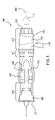
- FIG. 1 is a partially schematic cut-away view of an exemplary gas turbine engine in a first condition/configuration.
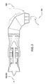
- FIG. 2 is a view of the engine of FIG. 1 in a second condition/configuration.
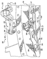
- FIG. 3 is a partial longitudinal view of a nozzle cooling valve of the engine of FIG. 1 in a first orientation.
- FIG. 4 is a partial longitudinal view of the nozzle cooling valve of the engine of FIG. 1 in a second orientation.
- FIG. 5 is a view of a linkage of the valve of FIG. 3 .
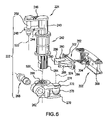
- FIG. 6 is an exploded view of the linkage of FIG. 5 .
- FIG. 7 is a partial longitudinal sectional view of valving and gate elements of the valve of FIG. 3 .
- FIG. 8 is an exploded partial view of a fastener and a gate element of the valve of FIG. 3 .
- FIGS. 1 and 2 show an exemplary engine 100 in two different configurations.
- FIG. 1 shows the engine 100 in a first configuration, such as a conventional take-off and landing (CTOL) configuration.
- FIG. 2 shows the engine 100 in a second configuration, such as a short take-off vertical landing (STOVL) configuration.
- FIG. 2 also shows, in phantom line, the engine 100 in transition between the CTOL and STOVL configurations.
- CTOL take-off and landing
- STOVL short take-off vertical landing
- the engine 100 has an inlet 101 , a compressor section 103 , a burner section 107 , a turbine section 109 , an afterburner section 111 , and a nozzle section 113 .
- the compressor section 103 includes a fan section 105 at the upstream end.
- the engine 100 also includes a bypass duct 115 for the secondary flow of air. The air flows through the engine 100 in the direction indicated by arrow F.
- the engine spools or rotors rotate about an axis 500 which may be at least partially coincident with an engine centerline 502 . In the STOVL configuration, the centerline 502 departs from the axis 500 downstream of the rotors.
- the nozzle section 113 includes a three bearing swivel duct 116 secured to the afterburner section 111 and a nozzle downstream of the duct.
- the three bearing swivel duct has three sections 117 , 119 , 121 .
- the first section 117 rotatably mounts to the afterburner section 111 .
- the second section 119 rotatably mounts to the first section 117 .
- the third section 121 rotatably mounts to the second section 119 .
- Conventional motors (not shown) can rotate the sections 117 , 119 , 121 to any desired exhaust path between the first configuration shown in FIG. 1 and the second configuration shown in FIG. 2 .
- the nozzle can be a conventional flap-type convergent-divergent nozzle 123 or any other suitable nozzle.
- the nozzle 123 is secured to the third section 121 of the swivel duct.
- the nozzle section 113 includes a liner (not shown).
- the liner separates the outer structure of the nozzle section 113 from the hot exhaust gases traveling through the nozzle section.
- the liner and the outer structure 126 of the nozzle section 113 form an annular chamber 127 ( FIG. 3 ).
- the engine 100 distributes cooling air through the annular chamber to cool the liner. After cooling the liner, the cooling air continues downstream to cool the nozzle flaps.
- a bleed (not shown) from the bypass duct 115 supplies the cooling air to the nozzle section 113 using conventional techniques.
- a valve assembly 200 ( FIG. 3 ) controls the amount of cooling air supplied to the nozzle flaps.
- the exemplary valve assembly includes an annular rotary gate 202 which may be rotated about the local engine centerline 502 ( FIG. 2 ).
- the gate 202 has a circumferential array of apertures 204 .
- the apertures 204 may have a degree of overlap with apertures 206 in a static element 208 abutting the gate 202 .
- the rotation of the gate 202 between first and second orientations determines the degree of aperture overlap (and thus of non-occlusion) and thus the effective flow area through the valve between minimum and maximum values.
- the minimum value may be zero (e.g., fully closed) or some greater amount.
- the FIG. 3 condition is approximately half occluded and may represent a minimum flow area condition.
- FIG. 4 shows essentially no occlusion and thus a maximum flow area condition.
- Rotation of the gate between the first and second orientations may be achieved by means of an actuator 220 acting via a linkage 222 .
- the exemplary linkage 222 includes a spindle 224 held for rotation about an axis 520 (e.g., a radial axis orthogonal to and intersecting the engine centerline).
- the actuator 220 may rotate the spindle 224 between first and second orientations associated with the first and second gate orientations/conditions.
- the actuator 220 may be pneumatic, hydraulic, electrical, electro-mechanical, or any other appropriate type.
- the actuator 220 may be constructed as in U.S. Pat. No. 6,694,723 (the '723 patent).
- FIGS. 3 and 4 show further details of the valve assembly 200 .
- the static element 208 is shown unitarily-formed with and extending radially inboard from a proximal/upstream portion of the outer structure 126 of the nozzle 123 .
- the exemplary gate 202 is immediately forward/upstream of the element 208 with the downstream face of the gate 202 facing the upstream face of the element 208 .
- the gate 202 is held for its rotation by support means (not shown).
- Exemplary support means could comprise a rotary bearing structure permitting rotation of the gate 202 but preventing longitudinal translation and radial shifts.
- Alternative means could include fasteners secured to one of the gate 202 and element 208 and having a limited range of motion (e.g., along a circumferential slot) in the other. In such a system, the slot ends could act as stops.
- Yet further alternative means could include an idler crank array as in the '723 patent providing a path combining rotation with longitudinal translation.
- FIGS. 5 and 6 show further details of the linkage 222 .
- a spindle 224 includes a spindle shaft 240 .
- An intermediate portion of the shaft 240 is received within a bushing 242 (e.g., a two-piece bushing).
- the bushing 242 may be secured within an aperture in the engine static structure (e.g., the exemplary third duct section 121 of FIG. 4 ).
- the shaft 240 is thus held by the bushing 242 for rotation about the axis 520 .
- An outboard portion of the spindle shaft 240 includes an input/driving clevis 244 .
- the exemplary clevis 244 is formed by arms 246 and 248 secured (e.g., by welding) to the shaft outboard portion.
- An input/driving pin 250 spans the arms 246 and 248 and has an axis 522 parallel to and spaced apart from the axis 520 .
- the pin 250 is engaged by the actuator to rotate the spindle 224 about the axis 520 .
- An inboard end of the spindle includes an output/driven clevis 260 .
- the exemplary clevis 260 includes a clevis body 262 separately formed from the spindle shaft and mounted thereon by means of complementary splines. Exemplary splines include external splines 264 ( FIG. 6 ) along the spindle shaft inboard portion and internal splines 266 within the body 262 .
- a bolt or other fastener 268 may extend through the body 262 spanning an expansion slot to secure the body 262 to the shaft 240 against translation.
- the body 262 includes arms 270 and 272 .
- a driven/output clevis pin 274 spans the arms and has an axis 524 parallel to and spaced apart from the axis 520 .
- Alternative implementations might include non-parallel axes 522 and/or 524 (e.g., axes intersecting the axis 520 or skew thereto).
- a spherical bearing 276 has an inner bore receiving the shaft of the pin 274 between the arms 270 and 272 . In the exemplary embodiment, the bearing 276 and shaft cooperate to permit the bearing to have non-zero ranges of movement along the axis 524 and rotation about the axis 524 .
- the bearing 276 is received within a slot 280 in a follower bracket 282 .
- the exemplary bracket 282 includes a base 284 for mounting to the gate 202 .
- a pair of arms 286 and 288 extend forward from the base 284 to define the slot 280 therebetween.
- Inboard surfaces 290 of the arms 286 and 288 have a concavity complementary to a convexity of the external surface of the bearing 276 .
- the exemplary surfaces 290 are singularly concave to allow the bearing 276 to translate along the slot from a proximal root of the slot to a distal end of the slot.
- the base 284 is secured against a forward/upstream surface of a web 300 of the gate 202 between inboard and outboard flanges. The securing may be by means of fasteners 302 (e.g., rivets).
- the base may further include a registration protrusion (not shown) for interfitting with a complementary aperture or socket 304 in the web 300
- movement of the actuator produces a rotation of the spindle 224 about the axis 520 .
- This tends to rotate the axis 524 about the axis 520 .
- Rotation of the axis 524 about the axis 520 causes the bearing 276 to transmit a tangential force and thus a torque (about the engine centerline) to the follower 282 and thus to the gate 202 .
- This torque causes rotation of the gate about the engine centerline so as to control the degree of aperture overlap and thus the flow through the valve.
- the axis 524 will tend to shift longitudinally (e.g., toward or away from the gate). This shift is accommodated by the sliding interaction of the bearing 276 longitudinally within the slot 280 and radially along the pin 274 . This sliding interaction decouples the longitudinal motion of the axis 524 from any longitudinal motion of the gate 202 .
- the gate 202 may exclusively rotate.
- the gate 202 may have a relatively small translation (e.g., if mounted by idler cranks in such a way that the permitted translation breaks a seal between the gate and the ring 208 ) so as to avoid sliding friction between the gate and ring.
- FIGS. 7 and 8 show further details of an exemplary gate support means.
- the means includes a circumferential array of fasteners 400 (e.g., between five and twenty bolts) secured to the element 208 .
- Each bolt 400 passes through and has a nonzero range of motion within an associated aperture 402 ( FIG. 8 ) in the gate 202 .
- Each exemplary aperture 402 is a circumferential slot having approximately semi-circular ends 404 and 406 joined by inboard and outboard circular cylindrical segment portions 408 and 410 .
- the exemplary bolts 400 each have an upstream head (e.g., a hex head) 412 .
- a first portion 414 extends distally/downstream thereof to a shoulder 416 separating it from a second portion 418 of smaller transverse sectional area.
- the exemplary portions 414 and 418 are circular cylindrical.
- a threaded downstream/distal end portion 420 carries a nut 422 .
- the second portion 418 is accommodated within an associated aperture 424 in the element 208 (e.g., a clearance fit accommodating manufacturing tolerances).
- the nut upstream face 426 bears against the downstream face 428 of the element 208 and the shoulder 416 bears against the upstream face 429 of the element 208 to hold the bolt in place.
- An associated flanged roller/bushing 430 has a sleeve 432 accommodated between each bolt first portion 414 and the associated slot 402 .
- a radially extending flange 434 extends outward at the sleeve upstream end.
- the radially extending flange 434 at the sleeve upstream end keeps the ring from falling forward during assembly and pressure reversals while running. It also controls the axial gap of the entire valve assembly.
- the roller inboard surface is in close sliding proximity to the outer surface of the first portion 414 .
- the roller sleeve outboard surface is closely accommodated within the slot 402 to guide the gate 202 during rotation between the maximum and minimum flow conditions.
- roller flange downstream surface 436 slidingly engages the gate upstream surface 437 to limit friction during rotation of the gate.
- roller rim surface 438 may slidingly engage the upstream surface 429 of the element 208 .
- Exemplary bolt, roller, and nut materials are nickel-based superalloys.
- the exemplary valve assembly 200 may be provided in the remanufacturing of a baseline engine or the reengineering of a baseline engine configuration.
- the baseline could lack such a valve assembly.
- the baseline could have a different valve assembly such as that of the '723 patent. This might be particularly relevant if the reengineering included elimination of the idler crank mounting means of the '723 patent in favor of a purely rotational gate movement.
Landscapes
- Engineering & Computer Science (AREA)
- Mechanical Engineering (AREA)
- General Engineering & Computer Science (AREA)
- Combustion & Propulsion (AREA)
- Chemical & Material Sciences (AREA)
- Environmental Sciences (AREA)
- Life Sciences & Earth Sciences (AREA)
- Animal Husbandry (AREA)
- Biodiversity & Conservation Biology (AREA)
- Control Of Turbines (AREA)
- Supercharger (AREA)
- Multiple-Way Valves (AREA)
- Structures Of Non-Positive Displacement Pumps (AREA)
- Mechanically-Actuated Valves (AREA)
- Sliding Valves (AREA)
Abstract
Description
Claims (14)
Priority Applications (10)
| Application Number | Priority Date | Filing Date | Title |
|---|---|---|---|
| US11/118,584 US7581382B2 (en) | 2005-04-28 | 2005-04-28 | Gas turbine engine air valve assembly |
| TW095104897A TW200641240A (en) | 2005-04-28 | 2006-02-14 | Gas turbine engine air valve assembly |
| AU2006200658A AU2006200658A1 (en) | 2005-04-28 | 2006-02-17 | Gas turbine engine air valve assembly |
| IL173839A IL173839A0 (en) | 2005-04-28 | 2006-02-21 | Gas turbine engine air valve assembly |
| CA002537621A CA2537621A1 (en) | 2005-04-28 | 2006-02-23 | Gas turbine engine air valve assembly |
| SG200601223A SG126822A1 (en) | 2005-04-28 | 2006-02-24 | Gas turbine engine air valve assembly |
| JP2006049569A JP2006307837A (en) | 2005-04-28 | 2006-02-27 | Air valve assembly of gas turbine engine |
| KR1020060018547A KR20060113380A (en) | 2005-04-28 | 2006-02-27 | Gas turbine engine air valve assembly |
| NO20060939A NO20060939L (en) | 2005-04-28 | 2006-02-27 | Gas turbine engine air valve assembly |
| EP20060251067 EP1719878B1 (en) | 2005-04-28 | 2006-02-28 | Gas turbine engine air valve assembly |
Applications Claiming Priority (1)
| Application Number | Priority Date | Filing Date | Title |
|---|---|---|---|
| US11/118,584 US7581382B2 (en) | 2005-04-28 | 2005-04-28 | Gas turbine engine air valve assembly |
Publications (2)
| Publication Number | Publication Date |
|---|---|
| US20090049837A1 US20090049837A1 (en) | 2009-02-26 |
| US7581382B2 true US7581382B2 (en) | 2009-09-01 |
Family
ID=36698722
Family Applications (1)
| Application Number | Title | Priority Date | Filing Date |
|---|---|---|---|
| US11/118,584 Active 2028-06-01 US7581382B2 (en) | 2005-04-28 | 2005-04-28 | Gas turbine engine air valve assembly |
Country Status (10)
| Country | Link |
|---|---|
| US (1) | US7581382B2 (en) |
| EP (1) | EP1719878B1 (en) |
| JP (1) | JP2006307837A (en) |
| KR (1) | KR20060113380A (en) |
| AU (1) | AU2006200658A1 (en) |
| CA (1) | CA2537621A1 (en) |
| IL (1) | IL173839A0 (en) |
| NO (1) | NO20060939L (en) |
| SG (1) | SG126822A1 (en) |
| TW (1) | TW200641240A (en) |
Cited By (9)
| Publication number | Priority date | Publication date | Assignee | Title |
|---|---|---|---|---|
| US20080236138A1 (en) * | 2005-09-27 | 2008-10-02 | Volvo Aero Corporation | Arrangement for Propelling an Aircraft, Aircraft and Outlet Nozzle for a Jet Engine |
| US20090217643A1 (en) * | 2008-02-29 | 2009-09-03 | Sokhey Jagdish S | Gas discharge device for a vehicle engine |
| US20120272522A1 (en) * | 2008-04-30 | 2012-11-01 | Andreas Sadil | Gas turbine engine systems and related methods involving thermally isolated retention |
| US20130042630A1 (en) * | 2011-08-19 | 2013-02-21 | United Technologies Corporation | Gas turbine engine accessory mount |
| US20140090398A1 (en) * | 2012-09-28 | 2014-04-03 | United Technologies Corporation | Flexible connection between a wall and a case of a turbine engine |
| US9057455B2 (en) | 2012-01-20 | 2015-06-16 | Hamilton Sundstrand Corporation | Crank |
| US9328735B2 (en) | 2012-09-28 | 2016-05-03 | United Technologies Corporation | Split ring valve |
| US20200056548A1 (en) * | 2018-08-14 | 2020-02-20 | United Technologies Corporation | Bleed valve actuation system |
| US20260009403A1 (en) * | 2022-10-04 | 2026-01-08 | Safran | Treatment of non-axisymmetric casing with controlled opening |
Families Citing this family (4)
| Publication number | Priority date | Publication date | Assignee | Title |
|---|---|---|---|---|
| US7854124B2 (en) * | 2006-10-27 | 2010-12-21 | United Technologies Corporation | Combined control for supplying cooling air and support air in a turbine engine nozzle |
| US20130232949A1 (en) * | 2012-03-09 | 2013-09-12 | Gary J. Dillard | Pressure balanced area control of high aspect ratio nozzle |
| FR3061739B1 (en) * | 2017-01-06 | 2020-07-31 | Safran Aircraft Engines | TURBOMACHINE SET |
| CN114562380B (en) * | 2022-01-13 | 2023-05-05 | 中国航发沈阳发动机研究所 | Adjustable gas injection pipe of rotatable actuator cylinder long distance |
Citations (7)
| Publication number | Priority date | Publication date | Assignee | Title |
|---|---|---|---|---|
| JPS6385226A (en) | 1986-09-29 | 1988-04-15 | Nissan Motor Co Ltd | Gas turbine engine |
| US5127224A (en) * | 1991-03-25 | 1992-07-07 | United Technologies Corporation | Spray-ring mounting assembly |
| US5370497A (en) * | 1991-10-24 | 1994-12-06 | Hitachi, Ltd. | Gas turbine and gas turbine nozzle |
| TW247341B (en) | 1993-10-27 | 1995-05-11 | Westinghouse Electric Corp | |
| US5592814A (en) * | 1994-12-21 | 1997-01-14 | United Technologies Corporation | Attaching brittle composite structures in gas turbine engines for resiliently accommodating thermal expansion |
| US5899058A (en) | 1997-05-20 | 1999-05-04 | United Technologies Corporation | Bypass air valve for a gas turbine engine |
| US20030205043A1 (en) * | 2002-03-27 | 2003-11-06 | Ward Eric J. | Valve assembly for gas turbine engine |
Family Cites Families (6)
| Publication number | Priority date | Publication date | Assignee | Title |
|---|---|---|---|---|
| DE3941715A1 (en) * | 1989-12-18 | 1991-06-20 | Porsche Ag | EXHAUST TURBOCHARGER FOR AN INTERNAL COMBUSTION ENGINE |
| GB2319307B (en) * | 1996-11-12 | 2000-11-08 | Rolls Royce Plc | Gas turbine engine cooling air flow control |
| WO1999037954A1 (en) * | 1998-01-26 | 1999-07-29 | Mitsubishi Heavy Industries, Ltd. | Bypass air volume control device for combustor used in gas turbine |
| JP2003004233A (en) * | 2001-06-26 | 2003-01-08 | Mitsubishi Heavy Ind Ltd | Bypass valve for compressed air and gas turbine |
| US6805165B2 (en) * | 2002-05-02 | 2004-10-19 | Dai-You Lin | Adjustable air stream introducing device |
| FR2860045B1 (en) * | 2003-09-24 | 2006-01-06 | Snecma Moteurs | VENTILATION SYSTEM FOR A DIVERGENT CONVERGENT EJECTION TUBE |
-
2005
- 2005-04-28 US US11/118,584 patent/US7581382B2/en active Active
-
2006
- 2006-02-14 TW TW095104897A patent/TW200641240A/en unknown
- 2006-02-17 AU AU2006200658A patent/AU2006200658A1/en not_active Abandoned
- 2006-02-21 IL IL173839A patent/IL173839A0/en unknown
- 2006-02-23 CA CA002537621A patent/CA2537621A1/en not_active Abandoned
- 2006-02-24 SG SG200601223A patent/SG126822A1/en unknown
- 2006-02-27 JP JP2006049569A patent/JP2006307837A/en active Pending
- 2006-02-27 KR KR1020060018547A patent/KR20060113380A/en not_active Abandoned
- 2006-02-27 NO NO20060939A patent/NO20060939L/en not_active Application Discontinuation
- 2006-02-28 EP EP20060251067 patent/EP1719878B1/en not_active Expired - Lifetime
Patent Citations (8)
| Publication number | Priority date | Publication date | Assignee | Title |
|---|---|---|---|---|
| JPS6385226A (en) | 1986-09-29 | 1988-04-15 | Nissan Motor Co Ltd | Gas turbine engine |
| US5127224A (en) * | 1991-03-25 | 1992-07-07 | United Technologies Corporation | Spray-ring mounting assembly |
| US5370497A (en) * | 1991-10-24 | 1994-12-06 | Hitachi, Ltd. | Gas turbine and gas turbine nozzle |
| TW247341B (en) | 1993-10-27 | 1995-05-11 | Westinghouse Electric Corp | |
| US5592814A (en) * | 1994-12-21 | 1997-01-14 | United Technologies Corporation | Attaching brittle composite structures in gas turbine engines for resiliently accommodating thermal expansion |
| US5899058A (en) | 1997-05-20 | 1999-05-04 | United Technologies Corporation | Bypass air valve for a gas turbine engine |
| US20030205043A1 (en) * | 2002-03-27 | 2003-11-06 | Ward Eric J. | Valve assembly for gas turbine engine |
| US6694723B2 (en) | 2002-03-27 | 2004-02-24 | United Technologies Corporation | Valve assembly for gas turbine engine |
Cited By (14)
| Publication number | Priority date | Publication date | Assignee | Title |
|---|---|---|---|---|
| US20080236138A1 (en) * | 2005-09-27 | 2008-10-02 | Volvo Aero Corporation | Arrangement for Propelling an Aircraft, Aircraft and Outlet Nozzle for a Jet Engine |
| US8061145B2 (en) * | 2005-09-27 | 2011-11-22 | Volvo Aero Corporation | Arrangement for propelling an aircraft, aircraft and outlet nozzle for a jet engine |
| US20090217643A1 (en) * | 2008-02-29 | 2009-09-03 | Sokhey Jagdish S | Gas discharge device for a vehicle engine |
| US8833721B2 (en) * | 2008-04-30 | 2014-09-16 | United Technologies Corporation | Gas turbine engine systems and related methods involving thermally isolated retention |
| US20120272522A1 (en) * | 2008-04-30 | 2012-11-01 | Andreas Sadil | Gas turbine engine systems and related methods involving thermally isolated retention |
| US20130042630A1 (en) * | 2011-08-19 | 2013-02-21 | United Technologies Corporation | Gas turbine engine accessory mount |
| US9057455B2 (en) | 2012-01-20 | 2015-06-16 | Hamilton Sundstrand Corporation | Crank |
| US20140090398A1 (en) * | 2012-09-28 | 2014-04-03 | United Technologies Corporation | Flexible connection between a wall and a case of a turbine engine |
| US9328735B2 (en) | 2012-09-28 | 2016-05-03 | United Technologies Corporation | Split ring valve |
| US9366185B2 (en) * | 2012-09-28 | 2016-06-14 | United Technologies Corporation | Flexible connection between a wall and a case of a turbine engine |
| US20200056548A1 (en) * | 2018-08-14 | 2020-02-20 | United Technologies Corporation | Bleed valve actuation system |
| US11149653B2 (en) * | 2018-08-14 | 2021-10-19 | Raytheon Technologies Corporation | Bleed valve actuation system having split ring segments and splice bracket |
| US20260009403A1 (en) * | 2022-10-04 | 2026-01-08 | Safran | Treatment of non-axisymmetric casing with controlled opening |
| US12546336B2 (en) * | 2022-10-04 | 2026-02-10 | Safran | Treatment of non-axisymmetric casing with controlled opening |
Also Published As
| Publication number | Publication date |
|---|---|
| SG126822A1 (en) | 2006-11-29 |
| KR20060113380A (en) | 2006-11-02 |
| EP1719878A3 (en) | 2009-09-16 |
| EP1719878A2 (en) | 2006-11-08 |
| NO20060939L (en) | 2006-10-30 |
| TW200641240A (en) | 2006-12-01 |
| US20090049837A1 (en) | 2009-02-26 |
| EP1719878B1 (en) | 2015-04-29 |
| JP2006307837A (en) | 2006-11-09 |
| AU2006200658A1 (en) | 2006-11-16 |
| IL173839A0 (en) | 2006-07-05 |
| CA2537621A1 (en) | 2006-10-28 |
Similar Documents
| Publication | Publication Date | Title |
|---|---|---|
| US7581382B2 (en) | Gas turbine engine air valve assembly | |
| JP4471566B2 (en) | Passage liner support device for gas turbine engine frame | |
| US9803559B2 (en) | Variable vane and seal arrangement | |
| US9328735B2 (en) | Split ring valve | |
| US10392969B2 (en) | Moment accommodating fastener assembly | |
| US10047629B2 (en) | Multi-segment adjustable stator vane for a variable area vane arrangement | |
| US9046272B2 (en) | Combustion liner assembly having a mount stake coupled to an upstream support | |
| US8015996B2 (en) | Gas turbine engine air valve assembly | |
| US11852029B2 (en) | Scoop assembly for rotational equipment | |
| US20260078681A1 (en) | Hub assembly having a ptich lock system | |
| US12410916B2 (en) | Annular dome assembly for a combustor | |
| EP3348799B1 (en) | Multi-flowpath fluid control valve | |
| EP3967912B1 (en) | Valve assembly and lockout mechanism | |
| EP3677837B1 (en) | Combustor cooling panel with flow guide | |
| US10746041B2 (en) | Shroud and shroud assembly process for variable vane assemblies | |
| US10801412B2 (en) | Pressure zone spraybars | |
| US20160169111A1 (en) | Pivoting stowable spraybar | |
| EP3431770B1 (en) | Clutched compressor section for gas turbine engine |
Legal Events
| Date | Code | Title | Description |
|---|---|---|---|
| AS | Assignment |
Owner name: UNITED TECHNOLOGIES CORPORATION, CONNECTICUT Free format text: ASSIGNMENT OF ASSIGNORS INTEREST;ASSIGNORS:SADIL, ANDREAS;ENGLEHART, JOSEPH F.;REEL/FRAME:016528/0452;SIGNING DATES FROM 20050426 TO 20050427 |
|
| STCF | Information on status: patent grant |
Free format text: PATENTED CASE |
|
| CC | Certificate of correction | ||
| FPAY | Fee payment |
Year of fee payment: 4 |
|
| FPAY | Fee payment |
Year of fee payment: 8 |
|
| AS | Assignment |
Owner name: RAYTHEON TECHNOLOGIES CORPORATION, MASSACHUSETTS Free format text: CHANGE OF NAME;ASSIGNOR:UNITED TECHNOLOGIES CORPORATION;REEL/FRAME:054062/0001 Effective date: 20200403 |
|
| MAFP | Maintenance fee payment |
Free format text: PAYMENT OF MAINTENANCE FEE, 12TH YEAR, LARGE ENTITY (ORIGINAL EVENT CODE: M1553); ENTITY STATUS OF PATENT OWNER: LARGE ENTITY Year of fee payment: 12 |
|
| AS | Assignment |
Owner name: RAYTHEON TECHNOLOGIES CORPORATION, CONNECTICUT Free format text: CORRECTIVE ASSIGNMENT TO CORRECT THE AND REMOVE PATENT APPLICATION NUMBER 11886281 AND ADD PATENT APPLICATION NUMBER 14846874. TO CORRECT THE RECEIVING PARTY ADDRESS PREVIOUSLY RECORDED AT REEL: 054062 FRAME: 0001. ASSIGNOR(S) HEREBY CONFIRMS THE CHANGE OF ADDRESS;ASSIGNOR:UNITED TECHNOLOGIES CORPORATION;REEL/FRAME:055659/0001 Effective date: 20200403 |
|
| AS | Assignment |
Owner name: RTX CORPORATION, CONNECTICUT Free format text: CHANGE OF NAME;ASSIGNOR:RAYTHEON TECHNOLOGIES CORPORATION;REEL/FRAME:064714/0001 Effective date: 20230714 |