EP1918527A2 - Ensemble moteur à turbine à gaz et et son procédé d'assemblage - Google Patents
Ensemble moteur à turbine à gaz et et son procédé d'assemblage Download PDFInfo
- Publication number
- EP1918527A2 EP1918527A2 EP07119445A EP07119445A EP1918527A2 EP 1918527 A2 EP1918527 A2 EP 1918527A2 EP 07119445 A EP07119445 A EP 07119445A EP 07119445 A EP07119445 A EP 07119445A EP 1918527 A2 EP1918527 A2 EP 1918527A2
- Authority
- EP
- European Patent Office
- Prior art keywords
- assembly
- coupled
- turbine engine
- low
- gas turbine
- Prior art date
- Legal status (The legal status is an assumption and is not a legal conclusion. Google has not performed a legal analysis and makes no representation as to the accuracy of the status listed.)
- Withdrawn
Links
Images


Classifications
-
- F—MECHANICAL ENGINEERING; LIGHTING; HEATING; WEAPONS; BLASTING
- F02—COMBUSTION ENGINES; HOT-GAS OR COMBUSTION-PRODUCT ENGINE PLANTS
- F02K—JET-PROPULSION PLANTS
- F02K3/00—Plants including a gas turbine driving a compressor or a ducted fan
- F02K3/02—Plants including a gas turbine driving a compressor or a ducted fan in which part of the working fluid by-passes the turbine and combustion chamber
- F02K3/04—Plants including a gas turbine driving a compressor or a ducted fan in which part of the working fluid by-passes the turbine and combustion chamber the plant including ducted fans, i.e. fans with high volume, low pressure outputs, for augmenting the jet thrust, e.g. of double-flow type
- F02K3/072—Plants including a gas turbine driving a compressor or a ducted fan in which part of the working fluid by-passes the turbine and combustion chamber the plant including ducted fans, i.e. fans with high volume, low pressure outputs, for augmenting the jet thrust, e.g. of double-flow type with counter-rotating, e.g. fan rotors
-
- F—MECHANICAL ENGINEERING; LIGHTING; HEATING; WEAPONS; BLASTING
- F01—MACHINES OR ENGINES IN GENERAL; ENGINE PLANTS IN GENERAL; STEAM ENGINES
- F01D—NON-POSITIVE DISPLACEMENT MACHINES OR ENGINES, e.g. STEAM TURBINES
- F01D15/00—Adaptations of machines or engines for special use; Combinations of engines with devices driven thereby
- F01D15/12—Combinations with mechanical gearing
-
- F—MECHANICAL ENGINEERING; LIGHTING; HEATING; WEAPONS; BLASTING
- F05—INDEXING SCHEMES RELATING TO ENGINES OR PUMPS IN VARIOUS SUBCLASSES OF CLASSES F01-F04
- F05D—INDEXING SCHEME FOR ASPECTS RELATING TO NON-POSITIVE-DISPLACEMENT MACHINES OR ENGINES, GAS-TURBINES OR JET-PROPULSION PLANTS
- F05D2260/00—Function
- F05D2260/40—Transmission of power
- F05D2260/403—Transmission of power through the shape of the drive components
- F05D2260/4031—Transmission of power through the shape of the drive components as in toothed gearing
- F05D2260/40311—Transmission of power through the shape of the drive components as in toothed gearing of the epicyclical, planetary or differential type
-
- Y—GENERAL TAGGING OF NEW TECHNOLOGICAL DEVELOPMENTS; GENERAL TAGGING OF CROSS-SECTIONAL TECHNOLOGIES SPANNING OVER SEVERAL SECTIONS OF THE IPC; TECHNICAL SUBJECTS COVERED BY FORMER USPC CROSS-REFERENCE ART COLLECTIONS [XRACs] AND DIGESTS
- Y02—TECHNOLOGIES OR APPLICATIONS FOR MITIGATION OR ADAPTATION AGAINST CLIMATE CHANGE
- Y02T—CLIMATE CHANGE MITIGATION TECHNOLOGIES RELATED TO TRANSPORTATION
- Y02T50/00—Aeronautics or air transport
- Y02T50/60—Efficient propulsion technologies, e.g. for aircraft
Definitions
- This invention relates generally to gas turbine engines, and more specifically to gas turbine engine assemblies that each include a booster compressor coupled to a low-pressure turbine and methods of assembling the same.
- At least some known gas turbine engines include a fan, a core engine, and a power turbine disposed downstream from the core engine.
- the core engine includes at least one compressor, a combustor, a high-pressure turbine and a low-pressure turbine disposed downstream from the core engine. More specifically, the compressor and high-pressure turbine are coupled through a shaft to define a high-pressure rotor assembly. Air entering the core engine is mixed with fuel and ignited to form a high energy gas stream. The high energy gas stream flows through the high-pressure turbine to rotatably drive the high-pressure turbine such that the shaft, in turn, rotatably drives the compressor.
- At least one known gas turbine engine includes a counter-rotating low-pressure turbine that is coupled to a counter-rotating fan and a booster compressor.
- An outer rotating spool, a rotating frame, a mid-turbine frame, and two concentric shafts, are installed within the gas turbine engine to facilitate supporting the counter-rotating low-pressure turbine.
- the installation of the aforementioned components also enables a first fan assembly to be coupled to a first turbine and a second fan assembly to be coupled to a second turbine such that the first fan assembly and the second fan assembly each rotate in the same rotational direction as the first turbine and the second turbine, respectively.
- the overall weight, design complexity and/or manufacturing costs of such an engine are increased.
- a method for assembling a gas turbine engine includes coupling a low-pressure turbine to a core turbine engine, coupling a counter-rotating fan assembly including a forward fan assembly and an axially aft fan assembly to the low-pressure turbine such that the forward fan assembly rotates in a first direction and the aft fan assembly rotates in an opposite second direction, and coupling a booster compressor directly to the low-pressure turbine such that the booster compressor rotates in the first direction.
- a gas turbine engine assembly in another aspect, includes a core gas turbine engine, a low-pressure turbine coupled to the core turbine engine, a counter-rotating fan assembly coupled to the low-pressure turbine, and a booster compressor coupled directly to the low-pressure turbine such that the booster compressor and the low-pressure turbine rotate in the same direction.
- Figure 1 is a cross-sectional view of a portion of an exemplary turbine engine assembly
- Figure 2 is an enlarged cross-sectional view of a portion of the counter-rotating fan assembly shown in Figure 1;
- Figure 3 is an enlarged cross-sectional view of a portion of the counter-rotating fan assembly shown in Figure 2;
- Figure 4 is an end view of the gearbox shown in Figure 3.
- Figure 5 is a side view of a portion of gearbox 100 shown in Figure 4.
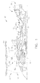
- FIG. 1 is a cross-sectional view of a portion of an exemplary turbine engine assembly 10 having a longitudinal axis 11.
- turbine engine assembly 10 includes a core gas turbine engine 12, a low-pressure turbine 14 that is disposed axially downstream from core gas turbine engine 12, and a counter-rotating fan assembly 16 that is disposed axially upstream from core gas turbine engine 12.
- Core gas turbine engine 12 includes an outer casing 20 that defines an annular core engine inlet 22.
- Casing 20 surrounds a low-pressure booster compressor 24 that is utilized to increase an operating pressure of the inlet air to a first pressure level.
- a high-pressure, multi-stage, axial-flow compressor 26 receives pressurized air from booster compressor 24 and further increases the pressure of the air to a second, higher operating pressure.
- the high-pressure air is channeled to a combustor 28 and is mixed with fuel.
- the fuel-air mixture is ignited to raise the temperature and energy level of the pressurized air.
- the high energy combustion products flow to a first or high-pressure turbine 30 for driving compressor 26 through a first drive shaft 32, and then to second or low-pressure turbine 14 to drive counter-rotating fan assembly 16 and booster compressor 24 through a second drive shaft 34 that is disposed coaxially inside first drive shaft 32.
- the exhaust stream is then discharged through an exhaust nozzle 36 to provide propulsive jet thrust.
- Counter-rotating fan assembly 16 includes a first or forward fan assembly 50 and a second or aft fan assembly 52 each of which is disposed about longitudinal centerline axis 11.
- the terms "forward fan” and “aft fan” are used herein to indicate that fan assembly 50 is disposed axially upstream from fan assembly 52.
- fan assemblies 50 and 52 are positioned at an upstream end of core gas turbine engine 12 as illustrated.
- fan assemblies 50 and 52 are each positioned at a downstream end of core gas turbine engine 12.
- Fan assemblies 50 and 52 each include at least one row of rotor blades 60 and 62, respectively, and are each positioned within a nacelle 64. Blades 60 and 62 are coupled to respective rotor disks 66 and 68.
- booster compressor 24 includes a plurality of rows of rotor blades 70 that are coupled to a respective rotor disk 72.
- booster compressor 24 is positioned downstream from an inlet guide vane assembly 74 and is coupled to low-pressure turbine 14 via shaft 34 which will be discussed in more detail below.
- booster compressor 24 is shown as having only three rows of rotor blades 70, it should be realized that booster compressor 24 may have a single row of rotor blades 70, or a plurality of rows of rotor blades 70 that are interdigitated with a plurality of rows of guide vanes 76.
- guide vanes 76 are fixedly coupled to a booster case 78. In another embodiment, guide vanes 76 are movable during engine operation to facilitate varying a quantity of air channeled through booster compressor 24.
- booster compressor 24 is disposed axially downstream from a fan frame assembly 67 such that fan frame assembly 67 is disposed axially between booster compressor 24 and aft fan assembly 52.
- Figure 2 is an enlarged cross-sectional view of a portion of turbine engine assembly 10 shown in Figure 1.
- Figure 3 is an enlarged cross-sectional view of a portion of turbine engine assembly 10 shown in Figure 2.
- first fan assembly 50 includes a cone 84 positioned about longitudinal axis 11.
- Cone 84 is connected at a first or forward end 86 to rotor disk 66, as shown in Figure 2, and at a second or downstream end 88 to a first output of a gearbox 100, as shown in Figure 3.
- Second fan assembly 52 includes a cone 90 positioned coaxially about at least a portion of cone 84 along longitudinal axis 11. Cone 90 is coupled at a first or forward end 92 to rotor disk 68 and at a second or downstream end 94 to a second output of gearbox 100.
- booster compressor 24 is directly coupled to low-pressure turbine 14 utilizing a flexible connection 150 such that booster compressor 24 rotates at the same rotational speed as low-pressure turbine 14 and in the same rotational direction.
- Low-pressure turbine 14 is coupled to gearbox 100 using shaft 34 to facilitate driving or rotating forward fan assembly 50 and aft fan assembly 52 via gearbox 100.
- forward fan assembly 50 rotates in a first rotational direction 80 and aft fan assembly 52 rotates in an opposite second direction 82.
- gearbox 100 is a dual-output gearbox that includes an input 104 that is coupled to shaft 34, a first output 105 that is coupled to downstream end 88 of cone 84, and a second output 106 that is coupled to downstream end 94 of cone 90.
- a first bearing assembly 110 such as a thrust bearing assembly, is positioned about drive shaft 34 and/or longitudinal axis 11.
- First bearing assembly 110 operatively couples and/or is mounted between drive shaft 34 and gearbox 100.
- thrust bearing assembly 110 includes a radially inner race 111 that is splined and/or coupled to a drive shaft extension 112 such that inner race 111 is rotatable about longitudinal axis 11 with drive shaft 34.
- drive shaft extension 112 is coupled between gearbox input 104 and drive shaft 34.
- Inner race 111 has a surface 113 defining an inner groove 114 of thrust bearing assembly 110.
- Surface 113 defining inner groove 114 has a generally arcuate profile.
- Thrust bearing assembly 110 includes a radially outer race 116 securely coupled to frame 13.
- outer race 116 and/or frame 13 acts as a ground for the transfer of thrust loads and/or forces developed or generated by counter-rotating fan assembly 16.
- Outer race 116 has a surface 117, generally opposing surface 113, which forms an outer groove 118 of thrust bearing assembly 110.
- Surface 117, defining outer groove 118 has a generally arcuate profile.
- At least one roller element, such as a plurality of bearings 119 is movably positioned between inner race 111 and outer race 116. Each bearing 119 is in rolling contact with inner groove 114 and outer groove 118 to allow drive shaft 34 to rotate freely with respect to structure 13.
- a second bearing assembly 120 such as a roller bearing assembly, is positioned radially about longitudinal axis 11.
- roller bearing assembly 120 is positioned radially inwardly from cone 84 at or near forward end 86 and radially outwardly of shaft 34.
- a second bearing assembly such as a ball bearing assembly 121 is positioned radially about longitudinal axis 11.
- ball bearing assembly 121 is positioned radially inwardly of cone 90 at or near forward end 92 and radially outwardly of cone 84.
- bearing assemblies 120 and 121 are bearings that function as differential bearing assemblies in combination with a fourth bearing assembly 130 to support first fan assembly 50 and/or transfer thrust loads and/or forces from first fan assembly 50 to first bearing assembly 110.
- fourth bearing assembly 130 is a thrust bearing that includes an outer race 136 that is coupled to cone 84 downstream end 88 and a radially inner race 138 that is coupled or splined to shaft 34.
- bearing assembly 130 acts as a ground for the transfer of thrust loads and/or forces developed or generated by first fan assembly 50.
- a fifth bearing assembly such as roller bearing assembly 140, is positioned about the outer surface of cone 90 at or near forward end 92, as shown in Figure 2.
- Fifth bearing assembly 140 includes a radially outer bearing race 142 that is coupled to fan frame 67 via a support structure 15, a radially inner race 144 that is coupled to forward end 92 of cone 90, and at least one rolling element 146 that is coupled within bearing races 142 and 144.
- Roller bearing assembly 140 acts to support second fan assembly 52 and/or transfer radial loads and/or forces from second fan assembly 52 to fan frame 67.
- turbofan engine assembly 10 may also include a differential bearing assembly 190 that is disposed between support structure 15 and cone 90 to provide rotational support for second fan assembly 52.
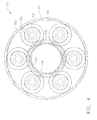
- Figure 4 is an end view of gearbox 100 shown in Figure 3.
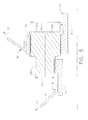
- Figure 5 is a side view of a portion of gearbox 100 shown in Figure 4.
- gearbox 100 is connected to a fixed or stationary component of gas turbine engine 10, such as frame 13 of core turbine engine 12, as shown in Figure 3.
- Gearbox 100 includes input 104 that is rotatably coupled to second drive shaft 34, first output 105 that is coupled to forward fan assembly 50 via cone 84, and second output 106 that is coupled to aft fan assembly 52 via cone 90.
- Gearbox 100 has a substantially toroidal cross-sectional profile and substantially circumscribes drive shaft 34.
- gearbox 100 includes a least one first or sun gear 300 that is coupled to input 104, and a plurality of second or planetary gears 302 that are each rotatably coupled to sun gear 300.
- gearbox 100 includes sun gear 300 and a set of planetary gears 302 cooperating to produce differential speeds.
- sun gear 300 is directly coupled to shaft 34, via input 104, and planetary gears 302 are disposed to intermesh with sun gear 300 and a ring gear 301 to facilitate driving aft fan assembly 52 via output 106.
- gearbox 100 includes a unitary support structure also referred to as a gorilla cage that is configured to support sun gear 300 and planetary gears 302.
- each planetary gear 302 is coupled to the support structure utilizing a fastener 304 such as a bolt for example that facilitates securing the planetary gears 302 within the support structure.
- each planetary gear 302 includes a respective bearing assembly 306 such that planetary gears 302 rotate freely with respect to sun gear 300.
- sun gear 300 has a diameter 340
- each planetary gear 302 includes a first gear portion 350 having a first diameter 360 and a second gear portion 352 having a second diameter 362, that is greater than first diameter 360, and is coupled axially aft from first gear portion 350.
- first and second gear portions are formed together such that each planetary gear 302 is a unitary structure.
- first and second gear portions 350 and 352 are formed separately and coupled together using a fastener (not shown).
- sun gear diameter 340, first gear portion diameter 360 and second gear portion diameter 362 are selected based on the desired rotational speeds of first and second fan assemblies 50 and 52, respectively.
- sun gear 300 is meshed or drivingly coupled to second gear portion 352. Since second gear portion 352 has a diameter 362 that is greater than the diameter 360 of first gear portion 350 the rotational speeds of both forward fan assembly 50 and aft fan assembly 52 will be set at a different rotational speed.
- sun gear 300 is meshed or drivingly coupled to first gear portion 350.
- each of sun gear 300, first gear portion 350 and second gear portion 352 can be varied to facilitate driving both forward and aft fan assemblies 50 and 52 at the desired rotational speeds. Additionally, since forward fan assembly 50 is rotatably coupled to first gear portion 350 and aft fan assembly 52 is rotatably coupled to second gear portion 352, and each has a different diameter, the rotational speeds of both fan assemblies are different, and can therefore be set to optimize the overall performance of the gas turbine fan assembly.
- second drive shaft 34 causes input 104 to rotate in first rotational direction 80, which subsequently rotates sun gear 300. Since sun gear 300 is rotatably coupled to first output 105, sun gear 300 facilitates driving forward fan assembly 50, via output 105 in the same direction as drive shaft 34. Additionally, since sun gear 300 is intermeshed with planetary gears 302, rotating sun gear 300 causes planetary gears 302 to rotate and thus drive aft fan assembly 52 via ring gear 301 through second output 106 in a second direction 82 that is opposite to the rotational direction of forward fan assembly 50.
- the gas turbine engine assembly described herein includes a dual output gearbox coupled between a high speed low-pressure turbine and a counter-rotating fan assembly to facilitate varying the rotational speed of one or both of the fan assemblies relative to the rotational speed of the low-pressure turbine.
- the booster compressor is directly coupled to the low-pressure turbine. This configuration enables the low-pressure turbine and booster compressor to operate at relatively high speeds thus increasing overall engine efficiency with nearly axial exit velocity, which simplifies the turbine rear frame and reduces low-pressure turbine exit area for weight and cost savings.
- the gear ratio for the forward fan assembly is approximately 1.7 to 1 and the gear ratio for the aft fan is approximately 2.6 to 1, to enable the aft fan to rotate at a rotational speed that is less than the rotational speed of the forward fan and thus improve overall engine efficiency.
- the gear ratios of the front fan and the aft fan assemblies may be further increased to define an engine with high bypass ratio and low fan pressure to facilitate minimizing the number of low-pressure turbine stages and thus reduce overall engine noise to meet the very low noise signature requirements currently being explored by various airplane manufacturers.
- the gas turbine engine assembly described herein utilizes a counter-rotating fan to increase fan efficiency, reduce fan tip speed, reduce noise, and/or reduce fan diameter compared to a single fan engine and also eliminates the bypass outlet guide vanes.
- the gas turbine engine assembly described herein does not include a counter-rotating low-pressure turbine, the mid turbine frame, the outer rotating spool, the rotating rear frame, a second low-pressure turbine shaft, and an outer rotating seal located between the outer rotating spool and the outer stationary casing may each be eliminated, thus reducing cost, weight, and design complexity.
- any gear losses occurring in the configuration described herein are offset by eliminating the significant counter-rotating low-pressure turbine outer seal leakage, and contains all the major changes from a conventional engine in the front of the geared engine for easy access.
- the gas turbine engine assembly described herein is estimated to be substantially lighter than known counter-rotating fan engines. As a result, the gas turbine engine assembly described herein is estimated to reduce fuel consumption by approximately 1.8% from known counter-rotating fan engines. Additionally, the gas turbine engine assembly described herein may more readily meet the low noise requirements and improved fuel-burn being demanded by the airline industry.
- FIG. 1 An exemplary embodiment of a gas turbine engine assembly that includes a booster compressor directly driven from the low-pressure turbine and a gearbox coupled to a counter-rotating fan assembly and are described above in detail.
- the components are not limited to the specific embodiments described herein, but rather, components of each system may be utilized independently and separately from other components described herein.
- the gearbox described herein can also be used in combination with other known gas turbine engines that include a forward and an aft fan assembly.
- gas turbine engine assembly 10 also includes a fuse 200 that is approximately disk shaped and includes a radially inner portion 230 that is coupled to input 104 via splines 216 and a radially outer portion 232 that is coupled to first portion 230 via splines 218.
- the thickness of fuse 200 is selected such that first portion 230 will separate from second portion 232, i.e. fuse 200 will break, when fuse 200 is subjected to a load and/or torque between approximately 45% and approximately 55% of the total torque load on the low-pressure turbine drive shaft.
Landscapes
- Engineering & Computer Science (AREA)
- Mechanical Engineering (AREA)
- General Engineering & Computer Science (AREA)
- Chemical & Material Sciences (AREA)
- Combustion & Propulsion (AREA)
- Structures Of Non-Positive Displacement Pumps (AREA)
- Retarders (AREA)
- Supercharger (AREA)
Applications Claiming Priority (1)
| Application Number | Priority Date | Filing Date | Title |
|---|---|---|---|
| US11/555,042 US7841165B2 (en) | 2006-10-31 | 2006-10-31 | Gas turbine engine assembly and methods of assembling same |
Publications (2)
| Publication Number | Publication Date |
|---|---|
| EP1918527A2 true EP1918527A2 (fr) | 2008-05-07 |
| EP1918527A3 EP1918527A3 (fr) | 2012-03-28 |
Family
ID=38691989
Family Applications (1)
| Application Number | Title | Priority Date | Filing Date |
|---|---|---|---|
| EP07119445A Withdrawn EP1918527A3 (fr) | 2006-10-31 | 2007-10-29 | Ensemble moteur à turbine à gaz et et son procédé d'assemblage |
Country Status (5)
| Country | Link |
|---|---|
| US (1) | US7841165B2 (fr) |
| EP (1) | EP1918527A3 (fr) |
| JP (2) | JP5486765B2 (fr) |
| CA (1) | CA2606736C (fr) |
| RU (1) | RU2468233C2 (fr) |
Cited By (12)
| Publication number | Priority date | Publication date | Assignee | Title |
|---|---|---|---|---|
| EP2535527A3 (fr) * | 2011-06-17 | 2014-02-26 | United Technologies Corporation | Turbosoufflante avec support de rotor de soufflante |
| EP2258929A3 (fr) * | 2009-05-22 | 2014-05-21 | United Technologies Corporation | Appareil et procédé de fourniture d'un liquide d'amortissement dans un moteur à turbine à gaz |
| US8911203B2 (en) | 2009-11-20 | 2014-12-16 | United Technologies Corporation | Fan rotor support |
| EP2809927A4 (fr) * | 2012-01-31 | 2015-12-16 | United Technologies Corp | Emplacement de sonde de capteur de vitesse dans une turbine à gaz |
| EP3045772A1 (fr) * | 2015-01-15 | 2016-07-20 | United Technologies Corporation | Moteur turbofan avec un système de transmission de couple divisé |
| FR3042011A1 (fr) * | 2015-10-05 | 2017-04-07 | Snecma | Ensemble de propulsion d'un aeronef equipe d'une soufflante principale et d'au moins une soufflante deportee |
| EP3187691A1 (fr) * | 2015-12-29 | 2017-07-05 | General Electric Company | Turboréacteur à double flux et procédé d'assemblage |
| US9869249B2 (en) | 2012-01-31 | 2018-01-16 | United Technologies Corporation | Speed sensor probe location in gas turbine engine |
| EP3460199A1 (fr) * | 2017-09-20 | 2019-03-27 | General Electric Company | Système de graissage pour section de turbine à engrenages |
| EP3901421A3 (fr) * | 2020-04-24 | 2021-11-17 | Raytheon Technologies Corporation | Compartiment de palier avant sans boîtier pour moteur à turbine à gaz |
| US11629649B2 (en) | 2020-05-11 | 2023-04-18 | Raytheon Technologies Corporation | Gas turbine engine with speed sensor |
| EP4170143A1 (fr) * | 2021-10-19 | 2023-04-26 | Raytheon Technologies Corporation | Compresseur basse pression monté à califourchon |
Families Citing this family (88)
| Publication number | Priority date | Publication date | Assignee | Title |
|---|---|---|---|---|
| WO2006060000A1 (fr) | 2004-12-01 | 2006-06-08 | United Technologies Corporation | Ensemble aubes de guidage d'admission de soufflante variable, turbomachine dotee d'un tel ensemble et procede de commande correspondant |
| US7493754B2 (en) * | 2005-10-19 | 2009-02-24 | General Electric Company | Gas turbine engine assembly and methods of assembling same |
| US7685808B2 (en) * | 2005-10-19 | 2010-03-30 | General Electric Company | Gas turbine engine assembly and methods of assembling same |
| US7493753B2 (en) * | 2005-10-19 | 2009-02-24 | General Electric Company | Gas turbine engine assembly and methods of assembling same |
| US7726113B2 (en) * | 2005-10-19 | 2010-06-01 | General Electric Company | Gas turbine engine assembly and methods of assembling same |
| US7603844B2 (en) * | 2005-10-19 | 2009-10-20 | General Electric Company | Gas turbine engine assembly and methods of assembling same |
| US7526913B2 (en) * | 2005-10-19 | 2009-05-05 | General Electric Company | Gas turbine engine assembly and methods of assembling same |
| US7490460B2 (en) * | 2005-10-19 | 2009-02-17 | General Electric Company | Gas turbine engine assembly and methods of assembling same |
| US7490461B2 (en) * | 2005-10-19 | 2009-02-17 | General Electric Company | Gas turbine engine assembly and methods of assembling same |
| US7513103B2 (en) * | 2005-10-19 | 2009-04-07 | General Electric Company | Gas turbine engine assembly and methods of assembling same |
| US20130019585A1 (en) * | 2007-05-11 | 2013-01-24 | Brian Merry | Variable fan inlet guide vane for turbine engine |
| US11242805B2 (en) * | 2007-08-01 | 2022-02-08 | Raytheon Technologies Corporation | Turbine section of high bypass turbofan |
| US8844265B2 (en) * | 2007-08-01 | 2014-09-30 | United Technologies Corporation | Turbine section of high bypass turbofan |
| US20150377124A1 (en) * | 2007-08-01 | 2015-12-31 | United Technologies Corporation | Turbine section of high bypass turbofan |
| US20150377123A1 (en) * | 2007-08-01 | 2015-12-31 | United Technologies Corporation | Turbine section of high bypass turbofan |
| US11486311B2 (en) * | 2007-08-01 | 2022-11-01 | Raytheon Technologies Corporation | Turbine section of high bypass turbofan |
| US11346289B2 (en) | 2007-08-01 | 2022-05-31 | Raytheon Technologies Corporation | Turbine section of high bypass turbofan |
| US11149650B2 (en) * | 2007-08-01 | 2021-10-19 | Raytheon Technologies Corporation | Turbine section of high bypass turbofan |
| US9701415B2 (en) | 2007-08-23 | 2017-07-11 | United Technologies Corporation | Gas turbine engine with axial movable fan variable area nozzle |
| US9494084B2 (en) | 2007-08-23 | 2016-11-15 | United Technologies Corporation | Gas turbine engine with fan variable area nozzle for low fan pressure ratio |
| US10167813B2 (en) | 2007-08-23 | 2019-01-01 | United Technologies Corporation | Gas turbine engine with fan variable area nozzle to reduce fan instability |
| US8590286B2 (en) * | 2007-12-05 | 2013-11-26 | United Technologies Corp. | Gas turbine engine systems involving tip fans |
| US8534074B2 (en) | 2008-05-13 | 2013-09-17 | Rolls-Royce Corporation | Dual clutch arrangement and method |
| US20140174056A1 (en) | 2008-06-02 | 2014-06-26 | United Technologies Corporation | Gas turbine engine with low stage count low pressure turbine |
| US8128021B2 (en) | 2008-06-02 | 2012-03-06 | United Technologies Corporation | Engine mount system for a turbofan gas turbine engine |
| US20100005810A1 (en) * | 2008-07-11 | 2010-01-14 | Rob Jarrell | Power transmission among shafts in a turbine engine |
| US8480527B2 (en) | 2008-08-27 | 2013-07-09 | Rolls-Royce Corporation | Gearing arrangement |
| US8075438B2 (en) | 2008-12-11 | 2011-12-13 | Rolls-Royce Corporation | Apparatus and method for transmitting a rotary input into counter-rotating outputs |
| US8021267B2 (en) | 2008-12-11 | 2011-09-20 | Rolls-Royce Corporation | Coupling assembly |
| US8191352B2 (en) * | 2008-12-19 | 2012-06-05 | General Electric Company | Geared differential speed counter-rotatable low pressure turbine |
| US8517672B2 (en) * | 2010-02-23 | 2013-08-27 | General Electric Company | Epicyclic gearbox |
| JP6018065B2 (ja) * | 2010-09-30 | 2016-11-02 | ゼネラル・エレクトリック・カンパニイ | 二系統燃料の航空機システムおよびそれを動作させるための方法 |
| US9541007B2 (en) * | 2011-04-15 | 2017-01-10 | United Technologies Corporation | Coupling shaft for gas turbine fan drive gear system |
| US9239012B2 (en) | 2011-06-08 | 2016-01-19 | United Technologies Corporation | Flexible support structure for a geared architecture gas turbine engine |
| US8770922B2 (en) | 2011-06-08 | 2014-07-08 | United Technologies Corporation | Flexible support structure for a geared architecture gas turbine engine |
| US9133729B1 (en) | 2011-06-08 | 2015-09-15 | United Technologies Corporation | Flexible support structure for a geared architecture gas turbine engine |
| US8814503B2 (en) | 2011-06-08 | 2014-08-26 | United Technologies Corporation | Flexible support structure for a geared architecture gas turbine engine |
| US8297917B1 (en) * | 2011-06-08 | 2012-10-30 | United Technologies Corporation | Flexible support structure for a geared architecture gas turbine engine |
| US9410608B2 (en) | 2011-06-08 | 2016-08-09 | United Technologies Corporation | Flexible support structure for a geared architecture gas turbine engine |
| US9631558B2 (en) | 2012-01-03 | 2017-04-25 | United Technologies Corporation | Geared architecture for high speed and small volume fan drive turbine |
| US9021778B2 (en) | 2011-06-28 | 2015-05-05 | United Technologies Corporation | Differential gear system with carrier drive |
| US9896966B2 (en) | 2011-08-29 | 2018-02-20 | United Technologies Corporation | Tie rod for a gas turbine engine |
| US20130186058A1 (en) | 2012-01-24 | 2013-07-25 | William G. Sheridan | Geared turbomachine fan and compressor rotation |
| US20130192251A1 (en) * | 2012-01-31 | 2013-08-01 | Peter M. Munsell | Buffer system that communicates buffer supply air to one or more portions of a gas turbine engine |
| US8246292B1 (en) * | 2012-01-31 | 2012-08-21 | United Technologies Corporation | Low noise turbine for geared turbofan engine |
| US9028200B2 (en) | 2012-02-29 | 2015-05-12 | United Technologies Corporation | Counter rotating low pressure turbine with splitter gear system |
| US9022725B2 (en) | 2012-02-29 | 2015-05-05 | United Technologies Corporation | Counter-rotating low pressure turbine with gear system mounted to turbine exhaust case |
| US20130219907A1 (en) | 2012-02-29 | 2013-08-29 | Frederick M. Schwarz | Geared turbofan architecture for improved thrust density |
| US9011076B2 (en) | 2012-02-29 | 2015-04-21 | United Technologies Corporation | Counter-rotating low pressure turbine with gear system mounted to turbine exhaust case |
| US9194290B2 (en) | 2012-02-29 | 2015-11-24 | United Technologies Corporation | Counter-rotating low pressure turbine without turbine exhaust case |
| US9080512B2 (en) | 2012-02-29 | 2015-07-14 | United Technologies Corporation | Counter-rotating low pressure turbine with gear system mounted to mid turbine frame |
| US10018119B2 (en) | 2012-04-02 | 2018-07-10 | United Technologies Corporation | Geared architecture with inducer for gas turbine engine |
| US10125693B2 (en) | 2012-04-02 | 2018-11-13 | United Technologies Corporation | Geared turbofan engine with power density range |
| US20130255274A1 (en) * | 2012-04-02 | 2013-10-03 | Daniel Bernard Kupratis | Geared architecture with speed change device for gas turbine engine |
| JP5915352B2 (ja) * | 2012-04-19 | 2016-05-11 | トヨタ自動車株式会社 | 変速機を備えたターボプロップ/ファン型ジェットエンジン |
| US8956108B2 (en) | 2012-05-11 | 2015-02-17 | Pratt & Whitney Canada Corp | Geared fan assembly |
| US8572943B1 (en) | 2012-05-31 | 2013-11-05 | United Technologies Corporation | Fundamental gear system architecture |
| US8756908B2 (en) | 2012-05-31 | 2014-06-24 | United Technologies Corporation | Fundamental gear system architecture |
| US20150308351A1 (en) | 2012-05-31 | 2015-10-29 | United Technologies Corporation | Fundamental gear system architecture |
| US9228535B2 (en) * | 2012-07-24 | 2016-01-05 | United Technologies Corporation | Geared fan with inner counter rotating compressor |
| US20160138474A1 (en) | 2012-09-28 | 2016-05-19 | United Technologies Corporation | Low noise compressor rotor for geared turbofan engine |
| US9624834B2 (en) | 2012-09-28 | 2017-04-18 | United Technologies Corporation | Low noise compressor rotor for geared turbofan engine |
| EP2904239B1 (fr) * | 2012-10-02 | 2020-05-06 | United Technologies Corporation | Assemblage comprenant un moteur à double flux à engrenage, un mât de liaison et une aile |
| US9777639B2 (en) | 2012-12-23 | 2017-10-03 | United Technologies Corporation | Turbine engine gearbox mount with multiple fuse joints |
| US9500133B2 (en) | 2012-12-23 | 2016-11-22 | United Technologies Corporation | Mount with an axial upstream linkage for connecting a gearbox to a turbine engine case |
| US8678743B1 (en) * | 2013-02-04 | 2014-03-25 | United Technologies Corporation | Method for setting a gear ratio of a fan drive gear system of a gas turbine engine |
| US9863326B2 (en) | 2013-03-12 | 2018-01-09 | United Technologies Corporation | Flexible coupling for geared turbine engine |
| US20140290211A1 (en) * | 2013-03-13 | 2014-10-02 | United Technologies Corporation | Turbine engine including balanced low pressure stage count |
| US10605172B2 (en) | 2013-03-14 | 2020-03-31 | United Technologies Corporation | Low noise turbine for geared gas turbine engine |
| US11719161B2 (en) | 2013-03-14 | 2023-08-08 | Raytheon Technologies Corporation | Low noise turbine for geared gas turbine engine |
| US9739205B2 (en) | 2013-12-23 | 2017-08-22 | United Technologies Corporation | Geared turbofan with a gearbox upstream of a fan drive turbine |
| US20160195010A1 (en) * | 2014-07-15 | 2016-07-07 | United Technologies Corporation | Vaneless counterrotating turbine |
| US10077660B2 (en) | 2014-12-03 | 2018-09-18 | General Electric Company | Turbine engine assembly and method of manufacturing |
| CA2915233C (fr) * | 2015-01-08 | 2018-12-04 | David A. Topol | Rotor de compresseur peu bruyant pour reacteur a reducteur |
| US10669946B2 (en) | 2015-06-05 | 2020-06-02 | Raytheon Technologies Corporation | Geared architecture for a gas turbine engine |
| US10119465B2 (en) | 2015-06-23 | 2018-11-06 | United Technologies Corporation | Geared turbofan with independent flexible ring gears and oil collectors |
| US9909451B2 (en) | 2015-07-09 | 2018-03-06 | General Electric Company | Bearing assembly for supporting a rotor shaft of a gas turbine engine |
| FR3043714B1 (fr) * | 2015-11-16 | 2017-12-22 | Snecma | Partie avant de turbomachine d'aeronef comprenant une soufflante unique entrainee par un reducteur, ainsi que des aubes directrices de sortie structurales agencees en partie en amont d'un bec de separation |
| US10465606B2 (en) * | 2017-02-08 | 2019-11-05 | General Electric Company | Counter rotating turbine with reversing reduction gearbox |
| US10823114B2 (en) | 2017-02-08 | 2020-11-03 | General Electric Company | Counter rotating turbine with reversing reduction gearbox |
| US10738646B2 (en) | 2017-06-12 | 2020-08-11 | Raytheon Technologies Corporation | Geared turbine engine with gear driving low pressure compressor and fan at common speed, and failsafe overspeed protection and shear section |
| US10612555B2 (en) | 2017-06-16 | 2020-04-07 | United Technologies Corporation | Geared turbofan with overspeed protection |
| US11002152B2 (en) * | 2019-02-14 | 2021-05-11 | Raytheon Technologies Corporation | Integrated fan inlet case and bearing support for a gas turbine engine |
| FR3098548B1 (fr) | 2019-07-08 | 2022-07-15 | Safran Trans Systems | Reducteur mecanique pour une turbomachine d’aeronef |
| CN114109596B (zh) * | 2020-08-31 | 2023-06-20 | 中国航发商用航空发动机有限责任公司 | 涡扇发动机 |
| US20220090512A1 (en) * | 2020-09-18 | 2022-03-24 | Ge Avio Srl | Turbomachine |
| US11428160B2 (en) | 2020-12-31 | 2022-08-30 | General Electric Company | Gas turbine engine with interdigitated turbine and gear assembly |
| CN115596556A (zh) * | 2021-07-08 | 2023-01-13 | 通用电气阿维奥有限责任公司(It) | 燃气涡轮发动机 |
Citations (6)
| Publication number | Priority date | Publication date | Assignee | Title |
|---|---|---|---|---|
| FR2121524A1 (fr) * | 1971-01-08 | 1972-08-25 | United Kingdom Government | |
| GB2195712A (en) * | 1986-10-08 | 1988-04-13 | Rolls Royce Plc | A turbofan gas turbine engine |
| GB2199375A (en) * | 1986-12-23 | 1988-07-06 | Rolls Royce Plc | A turbofan gas turbine engine |
| EP0521379A1 (fr) * | 1991-07-03 | 1993-01-07 | Mtu Motoren- Und Turbinen-Union MàNchen Gmbh | Propfan avec compresseur contrarotative à basse pression |
| DE19828562A1 (de) * | 1998-06-26 | 1999-12-30 | Mtu Muenchen Gmbh | Triebwerk mit gegenläufig drehenden Rotoren |
| EP1403500A1 (fr) * | 2002-09-30 | 2004-03-31 | General Electric Company | Réacteur comprenant des turbines contrarotatives basse pression à répartition variable de couple, des soufflantes contrarotatives, ainsi qu'un booster non contrarotatif |
Family Cites Families (28)
| Publication number | Priority date | Publication date | Assignee | Title |
|---|---|---|---|---|
| JPS4924242B1 (fr) * | 1970-04-28 | 1974-06-21 | ||
| US4102595A (en) * | 1976-10-19 | 1978-07-25 | General Electric Company | Bleed valve control system |
| US4964315A (en) * | 1984-10-03 | 1990-10-23 | General Electric Company | Transmission having dual counterrotating output shafts |
| GB2209575A (en) * | 1987-09-05 | 1989-05-17 | Rolls Royce Plc | A gearbox arrangement for driving contra-rotating multi-bladed rotors |
| DE3812027A1 (de) * | 1988-04-11 | 1989-10-26 | Mtu Muenchen Gmbh | Propfan-turbotriebwerk |
| DE3837994A1 (de) * | 1988-11-09 | 1990-05-10 | Mtu Muenchen Gmbh | Vorrichtung zur verstellung der rotorschaufeln eines propfan/turboproptriebwerkes |
| US5010729A (en) * | 1989-01-03 | 1991-04-30 | General Electric Company | Geared counterrotating turbine/fan propulsion system |
| US4969325A (en) * | 1989-01-03 | 1990-11-13 | General Electric Company | Turbofan engine having a counterrotating partially geared fan drive turbine |
| JPH1018860A (ja) * | 1996-04-30 | 1998-01-20 | Hiroyasu Tanigawa | 磁気動力伝達装置を含むエネルギ変換方法及び装置 |
| FR2749883B1 (fr) * | 1996-06-13 | 1998-07-31 | Snecma | Procede et support de palier permettant de maintenir en fonctionnement un turbomoteur pour aeronef apres apparition d'un balourd accidentel sur un rotor |
| US6240719B1 (en) * | 1998-12-09 | 2001-06-05 | General Electric Company | Fan decoupler system for a gas turbine engine |
| US6732502B2 (en) | 2002-03-01 | 2004-05-11 | General Electric Company | Counter rotating aircraft gas turbine engine with high overall pressure ratio compressor |
| US6619030B1 (en) | 2002-03-01 | 2003-09-16 | General Electric Company | Aircraft engine with inter-turbine engine frame supported counter rotating low pressure turbine rotors |
| US6739120B2 (en) | 2002-04-29 | 2004-05-25 | General Electric Company | Counterrotatable booster compressor assembly for a gas turbine engine |
| US6666017B2 (en) | 2002-05-24 | 2003-12-23 | General Electric Company | Counterrotatable booster compressor assembly for a gas turbine engine |
| US6846158B2 (en) * | 2002-09-06 | 2005-01-25 | General Electric Company | Method and apparatus for varying the critical speed of a shaft |
| US6763652B2 (en) * | 2002-09-24 | 2004-07-20 | General Electric Company | Variable torque split aircraft gas turbine engine counter rotating low pressure turbines |
| US6763653B2 (en) | 2002-09-24 | 2004-07-20 | General Electric Company | Counter rotating fan aircraft gas turbine engine with aft booster |
| FR2866074B1 (fr) * | 2004-02-11 | 2006-04-28 | Snecma Moteurs | Architecture d'un turboreacteur ayant une double soufflante a l'avant |
| FR2866073B1 (fr) * | 2004-02-11 | 2006-07-28 | Snecma Moteurs | Turboreacteur ayant deux soufflantes contrarotatives solidaires d'un compresseur a basse pression contrarotatif |
| FR2866387B1 (fr) * | 2004-02-12 | 2008-03-14 | Snecma Moteurs | Adaptation aerodynamique de la soufflante arriere d'un turboreacteur double soufflante |
| RU2264553C1 (ru) * | 2004-04-23 | 2005-11-20 | ЗАО "Энергетика" | Турбореактивный двигатель |
| DE102004042739A1 (de) * | 2004-09-03 | 2006-03-09 | Mtu Aero Engines Gmbh | Fan für ein Flugtriebwerk sowie Flugtriebwerk |
| US7096674B2 (en) | 2004-09-15 | 2006-08-29 | General Electric Company | High thrust gas turbine engine with improved core system |
| US7093446B2 (en) | 2004-09-15 | 2006-08-22 | General Electric Company | Gas turbine engine having improved core system |
| SE527711C2 (sv) * | 2004-10-06 | 2006-05-16 | Volvo Aero Corp | Lagerstativstruktur och gasturbinmotor som innefattar lagerstativstrukturen |
| US7334392B2 (en) * | 2004-10-29 | 2008-02-26 | General Electric Company | Counter-rotating gas turbine engine and method of assembling same |
| FR2878289A1 (fr) * | 2004-11-19 | 2006-05-26 | Snecma Moteurs Sa | Turbomachine avec un dispositif de decouplage commun aux premier et deuxieme paliers de son arbre d'entrainement |
-
2006
- 2006-10-31 US US11/555,042 patent/US7841165B2/en not_active Expired - Fee Related
-
2007
- 2007-10-18 CA CA2606736A patent/CA2606736C/fr not_active Expired - Fee Related
- 2007-10-26 JP JP2007278711A patent/JP5486765B2/ja not_active Expired - Fee Related
- 2007-10-29 EP EP07119445A patent/EP1918527A3/fr not_active Withdrawn
- 2007-10-30 RU RU2007140321/06A patent/RU2468233C2/ru not_active IP Right Cessation
-
2012
- 2012-01-30 JP JP2012016441A patent/JP2012132462A/ja active Pending
Patent Citations (6)
| Publication number | Priority date | Publication date | Assignee | Title |
|---|---|---|---|---|
| FR2121524A1 (fr) * | 1971-01-08 | 1972-08-25 | United Kingdom Government | |
| GB2195712A (en) * | 1986-10-08 | 1988-04-13 | Rolls Royce Plc | A turbofan gas turbine engine |
| GB2199375A (en) * | 1986-12-23 | 1988-07-06 | Rolls Royce Plc | A turbofan gas turbine engine |
| EP0521379A1 (fr) * | 1991-07-03 | 1993-01-07 | Mtu Motoren- Und Turbinen-Union MàNchen Gmbh | Propfan avec compresseur contrarotative à basse pression |
| DE19828562A1 (de) * | 1998-06-26 | 1999-12-30 | Mtu Muenchen Gmbh | Triebwerk mit gegenläufig drehenden Rotoren |
| EP1403500A1 (fr) * | 2002-09-30 | 2004-03-31 | General Electric Company | Réacteur comprenant des turbines contrarotatives basse pression à répartition variable de couple, des soufflantes contrarotatives, ainsi qu'un booster non contrarotatif |
Cited By (20)
| Publication number | Priority date | Publication date | Assignee | Title |
|---|---|---|---|---|
| EP2258929A3 (fr) * | 2009-05-22 | 2014-05-21 | United Technologies Corporation | Appareil et procédé de fourniture d'un liquide d'amortissement dans un moteur à turbine à gaz |
| US9790855B2 (en) | 2009-05-22 | 2017-10-17 | United Technologies Corporation | Apparatus and method for providing damper liquid in a gas turbine engine |
| US8911203B2 (en) | 2009-11-20 | 2014-12-16 | United Technologies Corporation | Fan rotor support |
| EP2535527A3 (fr) * | 2011-06-17 | 2014-02-26 | United Technologies Corporation | Turbosoufflante avec support de rotor de soufflante |
| EP2809927B1 (fr) | 2012-01-31 | 2017-11-01 | United Technologies Corporation | Emplacement de sonde de capteur de vitesse dans une turbine à gaz |
| EP2809927A4 (fr) * | 2012-01-31 | 2015-12-16 | United Technologies Corp | Emplacement de sonde de capteur de vitesse dans une turbine à gaz |
| US9869249B2 (en) | 2012-01-31 | 2018-01-16 | United Technologies Corporation | Speed sensor probe location in gas turbine engine |
| EP3045772A1 (fr) * | 2015-01-15 | 2016-07-20 | United Technologies Corporation | Moteur turbofan avec un système de transmission de couple divisé |
| US10072571B2 (en) | 2015-01-15 | 2018-09-11 | United Technologies Corporation | Gas turbine engine split torque fan drive gear system |
| FR3042011A1 (fr) * | 2015-10-05 | 2017-04-07 | Snecma | Ensemble de propulsion d'un aeronef equipe d'une soufflante principale et d'au moins une soufflante deportee |
| CN107023334A (zh) * | 2015-12-29 | 2017-08-08 | 通用电气公司 | 涡轮风扇发动机组件及其组装方法 |
| EP3187691A1 (fr) * | 2015-12-29 | 2017-07-05 | General Electric Company | Turboréacteur à double flux et procédé d'assemblage |
| CN107023334B (zh) * | 2015-12-29 | 2019-04-30 | 通用电气公司 | 涡轮风扇发动机组件及其组装方法 |
| US10760589B2 (en) | 2015-12-29 | 2020-09-01 | General Electric Company | Turbofan engine assembly and methods of assembling the same |
| EP3460199A1 (fr) * | 2017-09-20 | 2019-03-27 | General Electric Company | Système de graissage pour section de turbine à engrenages |
| US11255221B2 (en) | 2017-09-20 | 2022-02-22 | General Electric Company | Lube system for geared turbine section |
| EP3901421A3 (fr) * | 2020-04-24 | 2021-11-17 | Raytheon Technologies Corporation | Compartiment de palier avant sans boîtier pour moteur à turbine à gaz |
| US11352979B2 (en) | 2020-04-24 | 2022-06-07 | Raytheon Technologies Corporation | Housing less front bearing compartment for gas turbine engine |
| US11629649B2 (en) | 2020-05-11 | 2023-04-18 | Raytheon Technologies Corporation | Gas turbine engine with speed sensor |
| EP4170143A1 (fr) * | 2021-10-19 | 2023-04-26 | Raytheon Technologies Corporation | Compresseur basse pression monté à califourchon |
Also Published As
| Publication number | Publication date |
|---|---|
| CA2606736C (fr) | 2016-04-05 |
| CA2606736A1 (fr) | 2008-04-30 |
| JP5486765B2 (ja) | 2014-05-07 |
| RU2007140321A (ru) | 2009-05-10 |
| JP2008115856A (ja) | 2008-05-22 |
| US7841165B2 (en) | 2010-11-30 |
| EP1918527A3 (fr) | 2012-03-28 |
| US20080098716A1 (en) | 2008-05-01 |
| JP2012132462A (ja) | 2012-07-12 |
| RU2468233C2 (ru) | 2012-11-27 |
Similar Documents
| Publication | Publication Date | Title |
|---|---|---|
| CA2606736C (fr) | Ensemble de turbine a gaz et methodes d'assemblage | |
| US7752836B2 (en) | Gas turbine assembly and methods of assembling same | |
| US7526913B2 (en) | Gas turbine engine assembly and methods of assembling same | |
| US7513103B2 (en) | Gas turbine engine assembly and methods of assembling same | |
| US7493754B2 (en) | Gas turbine engine assembly and methods of assembling same | |
| US7726113B2 (en) | Gas turbine engine assembly and methods of assembling same | |
| US7832193B2 (en) | Gas turbine engine assembly and methods of assembling same | |
| US7490461B2 (en) | Gas turbine engine assembly and methods of assembling same | |
| US7685808B2 (en) | Gas turbine engine assembly and methods of assembling same | |
| US7490460B2 (en) | Gas turbine engine assembly and methods of assembling same | |
| US7493753B2 (en) | Gas turbine engine assembly and methods of assembling same | |
| EP1921253B1 (fr) | Assemblage de moteur de réacteur à double flux | |
| CA2606860A1 (fr) | Turbosoufflante et methode de montage connexe |
Legal Events
| Date | Code | Title | Description |
|---|---|---|---|
| PUAI | Public reference made under article 153(3) epc to a published international application that has entered the european phase |
Free format text: ORIGINAL CODE: 0009012 |
|
| AK | Designated contracting states |
Kind code of ref document: A2 Designated state(s): AT BE BG CH CY CZ DE DK EE ES FI FR GB GR HU IE IS IT LI LT LU LV MC MT NL PL PT RO SE SI SK TR |
|
| AX | Request for extension of the european patent |
Extension state: AL BA HR MK RS |
|
| PUAL | Search report despatched |
Free format text: ORIGINAL CODE: 0009013 |
|
| AK | Designated contracting states |
Kind code of ref document: A3 Designated state(s): AT BE BG CH CY CZ DE DK EE ES FI FR GB GR HU IE IS IT LI LT LU LV MC MT NL PL PT RO SE SI SK TR |
|
| AX | Request for extension of the european patent |
Extension state: AL BA HR MK RS |
|
| RIC1 | Information provided on ipc code assigned before grant |
Ipc: F02K 3/072 20060101ALI20120217BHEP Ipc: F01D 15/12 20060101AFI20120217BHEP |
|
| 17P | Request for examination filed |
Effective date: 20120928 |
|
| AKX | Designation fees paid |
Designated state(s): DE FR GB IT |
|
| STAA | Information on the status of an ep patent application or granted ep patent |
Free format text: STATUS: THE APPLICATION IS DEEMED TO BE WITHDRAWN |
|
| 18D | Application deemed to be withdrawn |
Effective date: 20170503 |