EP1918522A2 - Turbinenbauteil - Google Patents
Turbinenbauteil Download PDFInfo
- Publication number
- EP1918522A2 EP1918522A2 EP07254134A EP07254134A EP1918522A2 EP 1918522 A2 EP1918522 A2 EP 1918522A2 EP 07254134 A EP07254134 A EP 07254134A EP 07254134 A EP07254134 A EP 07254134A EP 1918522 A2 EP1918522 A2 EP 1918522A2
- Authority
- EP
- European Patent Office
- Prior art keywords
- cooling
- airfoil
- trailing edge
- path
- tip flag
- Prior art date
- Legal status (The legal status is an assumption and is not a legal conclusion. Google has not performed a legal analysis and makes no representation as to the accuracy of the status listed.)
- Granted
Links
- 238000001816 cooling Methods 0.000 claims abstract description 82
- NJPPVKZQTLUDBO-UHFFFAOYSA-N novaluron Chemical compound C1=C(Cl)C(OC(F)(F)C(OC(F)(F)F)F)=CC=C1NC(=O)NC(=O)C1=C(F)C=CC=C1F NJPPVKZQTLUDBO-UHFFFAOYSA-N 0.000 claims abstract description 25
- 238000003491 array Methods 0.000 abstract 1
- 238000002485 combustion reaction Methods 0.000 description 7
- 239000000919 ceramic Substances 0.000 description 3
- 239000000446 fuel Substances 0.000 description 3
- 239000011796 hollow space material Substances 0.000 description 3
- 238000000034 method Methods 0.000 description 2
- 238000010248 power generation Methods 0.000 description 2
- 238000000576 coating method Methods 0.000 description 1
- 238000005495 investment casting Methods 0.000 description 1
- 239000000203 mixture Substances 0.000 description 1
- 238000012986 modification Methods 0.000 description 1
- 230000004048 modification Effects 0.000 description 1
- 230000003647 oxidation Effects 0.000 description 1
- 238000007254 oxidation reaction Methods 0.000 description 1
- 230000003068 static effect Effects 0.000 description 1
Images
Classifications
-
- F—MECHANICAL ENGINEERING; LIGHTING; HEATING; WEAPONS; BLASTING
- F01—MACHINES OR ENGINES IN GENERAL; ENGINE PLANTS IN GENERAL; STEAM ENGINES
- F01D—NON-POSITIVE DISPLACEMENT MACHINES OR ENGINES, e.g. STEAM TURBINES
- F01D5/00—Blades; Blade-carrying members; Heating, heat-insulating, cooling or antivibration means on the blades or the members
- F01D5/12—Blades
- F01D5/14—Form or construction
- F01D5/18—Hollow blades, i.e. blades with cooling or heating channels or cavities; Heating, heat-insulating or cooling means on blades
- F01D5/187—Convection cooling
-
- F—MECHANICAL ENGINEERING; LIGHTING; HEATING; WEAPONS; BLASTING
- F01—MACHINES OR ENGINES IN GENERAL; ENGINE PLANTS IN GENERAL; STEAM ENGINES
- F01D—NON-POSITIVE DISPLACEMENT MACHINES OR ENGINES, e.g. STEAM TURBINES
- F01D25/00—Component parts, details, or accessories, not provided for in, or of interest apart from, other groups
- F01D25/08—Cooling; Heating; Heat-insulation
- F01D25/12—Cooling
-
- F—MECHANICAL ENGINEERING; LIGHTING; HEATING; WEAPONS; BLASTING
- F01—MACHINES OR ENGINES IN GENERAL; ENGINE PLANTS IN GENERAL; STEAM ENGINES
- F01D—NON-POSITIVE DISPLACEMENT MACHINES OR ENGINES, e.g. STEAM TURBINES
- F01D5/00—Blades; Blade-carrying members; Heating, heat-insulating, cooling or antivibration means on the blades or the members
- F01D5/02—Blade-carrying members, e.g. rotors
- F01D5/08—Heating, heat-insulating or cooling means
-
- F—MECHANICAL ENGINEERING; LIGHTING; HEATING; WEAPONS; BLASTING
- F02—COMBUSTION ENGINES; HOT-GAS OR COMBUSTION-PRODUCT ENGINE PLANTS
- F02C—GAS-TURBINE PLANTS; AIR INTAKES FOR JET-PROPULSION PLANTS; CONTROLLING FUEL SUPPLY IN AIR-BREATHING JET-PROPULSION PLANTS
- F02C7/00—Features, components parts, details or accessories, not provided for in, or of interest apart form groups F02C1/00 - F02C6/00; Air intakes for jet-propulsion plants
- F02C7/12—Cooling of plants
-
- F—MECHANICAL ENGINEERING; LIGHTING; HEATING; WEAPONS; BLASTING
- F05—INDEXING SCHEMES RELATING TO ENGINES OR PUMPS IN VARIOUS SUBCLASSES OF CLASSES F01-F04
- F05D—INDEXING SCHEME FOR ASPECTS RELATING TO NON-POSITIVE-DISPLACEMENT MACHINES OR ENGINES, GAS-TURBINES OR JET-PROPULSION PLANTS
- F05D2240/00—Components
- F05D2240/10—Stators
- F05D2240/12—Fluid guiding means, e.g. vanes
- F05D2240/122—Fluid guiding means, e.g. vanes related to the trailing edge of a stator vane
-
- F—MECHANICAL ENGINEERING; LIGHTING; HEATING; WEAPONS; BLASTING
- F05—INDEXING SCHEMES RELATING TO ENGINES OR PUMPS IN VARIOUS SUBCLASSES OF CLASSES F01-F04
- F05D—INDEXING SCHEME FOR ASPECTS RELATING TO NON-POSITIVE-DISPLACEMENT MACHINES OR ENGINES, GAS-TURBINES OR JET-PROPULSION PLANTS
- F05D2240/00—Components
- F05D2240/20—Rotors
- F05D2240/30—Characteristics of rotor blades, i.e. of any element transforming dynamic fluid energy to or from rotational energy and being attached to a rotor
- F05D2240/304—Characteristics of rotor blades, i.e. of any element transforming dynamic fluid energy to or from rotational energy and being attached to a rotor related to the trailing edge of a rotor blade
-
- F—MECHANICAL ENGINEERING; LIGHTING; HEATING; WEAPONS; BLASTING
- F05—INDEXING SCHEMES RELATING TO ENGINES OR PUMPS IN VARIOUS SUBCLASSES OF CLASSES F01-F04
- F05D—INDEXING SCHEME FOR ASPECTS RELATING TO NON-POSITIVE-DISPLACEMENT MACHINES OR ENGINES, GAS-TURBINES OR JET-PROPULSION PLANTS
- F05D2260/00—Function
- F05D2260/20—Heat transfer, e.g. cooling
- F05D2260/221—Improvement of heat transfer
- F05D2260/2212—Improvement of heat transfer by creating turbulence
-
- F—MECHANICAL ENGINEERING; LIGHTING; HEATING; WEAPONS; BLASTING
- F05—INDEXING SCHEMES RELATING TO ENGINES OR PUMPS IN VARIOUS SUBCLASSES OF CLASSES F01-F04
- F05D—INDEXING SCHEME FOR ASPECTS RELATING TO NON-POSITIVE-DISPLACEMENT MACHINES OR ENGINES, GAS-TURBINES OR JET-PROPULSION PLANTS
- F05D2260/00—Function
- F05D2260/20—Heat transfer, e.g. cooling
- F05D2260/221—Improvement of heat transfer
- F05D2260/2214—Improvement of heat transfer by increasing the heat transfer surface
- F05D2260/22141—Improvement of heat transfer by increasing the heat transfer surface using fins or ribs
-
- Y—GENERAL TAGGING OF NEW TECHNOLOGICAL DEVELOPMENTS; GENERAL TAGGING OF CROSS-SECTIONAL TECHNOLOGIES SPANNING OVER SEVERAL SECTIONS OF THE IPC; TECHNICAL SUBJECTS COVERED BY FORMER USPC CROSS-REFERENCE ART COLLECTIONS [XRACs] AND DIGESTS
- Y02—TECHNOLOGIES OR APPLICATIONS FOR MITIGATION OR ADAPTATION AGAINST CLIMATE CHANGE
- Y02T—CLIMATE CHANGE MITIGATION TECHNOLOGIES RELATED TO TRANSPORTATION
- Y02T50/00—Aeronautics or air transport
- Y02T50/60—Efficient propulsion technologies, e.g. for aircraft
Definitions
- This application relates to a turbine component, such as a turbine blade, wherein a tip flag is provided to direct cooling air to a radially outer portion of the trailing edge of the blade. Pedestals in the area of the radially outer portion of the trailing edge provide additional cooling at a particularly challenging area.
- Gas turbine engines are known, and include a plurality of sections mounted along a serial flow path.
- a fan directs air into a compressor where it is compressed.
- the compressed air is delivered into a combustion section.
- the combustion section the compressed air is mixed with fuel and combusted.
- Products of combustion pass downstream over turbine rotors.
- the turbine rotors are driven by the products of combustion, and drive the fan and compressor sections.
- the turbine includes a plurality of rotors each having circumferentially spaced blades that are removable from the rotor.
- stationary vanes are positioned adjacent to the turbine rotors.
- the products of combustion are hot, and thus the rotor blades and vanes are exposed to high temperatures.
- One method to address the high temperatures experienced by the blades is the use of internal air cooling passages in the blade airfoil.
- the design of turbine blades includes optimizing air cooling passages.
- One standard type of passage is a serpentine path. In a serpentine path, cooling air is directed radially outwardly from an inner platform of the blade and toward an outer tip of the blade. The air reaches the outer tip of the blade and circulates back toward the platform, eventually returning again back radially outwardly.
- Another type of cooling air passage directs air along a length of the airfoil, and then direct the air outwardly to openings at a trailing edge. This type of cooling air passage is often utilized with a plurality of metering openings which meter the amount of air being delivered to trailing edge skin cooling openings:
- the cooling of the radially outermost portion of the airfoil at the trailing edge has proven problematic.
- the cooling air path delivering air to the trailing edge has delivered much of its air outwardly for skin cooling before reaching the radially outer portion of the trailing edge.
- cooling is not as effective as it is at radially inner locations.
- additional cooling has been delivered by a tip flag including a divider directing some air from a radially outer part of the serpentine path to the radially outer portion of the traveling edge.
- This air provides additional cooling to the area in question.
- additional cooling is still necessary.
- One further refinement of the tip flag concept is to provide trip strips on the walls of the blade along the tip flag path. These tip strips create turbulence in the airflow, and thus increase cooling. Even so, there are still problems with spallation of external coatings, burning, and oxidation at the area in question.
- additional cooling is provided at the radially outer trailing edge of a turbine component having an airfoil.
- a tip flag is utilized to direct cooling air to the radially outermost portion of the trailing edge.
- the tip flag is provided with a heat transfer pedestal array along a tip flag path, with the pedestals providing additional heat transfer surfaces to remove additional heat from the airfoil.
- the radially outermost portions of the areas of the airfoil which are cooled by the direct flow, and through the metering holes are also improved.
- the last few metering holes are replaced by a pedestal array.
- the pedestal array provides additional heat transfer surfaces which remove heat from the area in question.
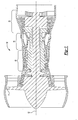
- Figure 1 shows a gas turbine engine 10, such as a gas turbine used for power generation or propulsion, circumferentially disposed about an engine centerline, or axial centerline axis 12.
- the engine 10 includes a fan 11, compressors 11, 13, a combustion section 14 and a turbine 15.
- air compressed in the compressors is mixed with fuel which is burned in the combustion section 40 and expanded in turbine 15.
- the air compressed in the compressor and the fuel mixture expanded in the turbine 15 can both be referred to as a hot gas stream flow.
- the turbine 15 includes rotors that, in response to the expansion, rotate, driving the compressors and fan.
- the turbine 15 comprises alternating rows of rotary blades 30 and static airfoils or vanes 19.
- Figure 1 is a somewhat schematic representation, for illustrative purposes only, and is not a limitation of the instant invention, that may be employed on gas turbines used for electrical power generation and aircraft.
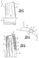
- Figure 2 shows a turbine blade 30 having an airfoil 31 and a platform 38.
- the platform 38 serves to mount the turbine blade 30 in a turbine rotor.
- the airfoil 31 extends from a leading edge 32 to a trailing edge 34.
- Skin cooling openings 36 are provided at the trailing edge and cooling air is directed outwardly through those openings to cooling the trailing edge.
- the airfoil 31 has a curved shape, between a wall 29 and a wall 27. As is known, these walls define a generally hollow space, and internal cooling flow passages such as shown in 40 and 42 are formed within the hollow space.
- the hollow space is generally formed by a ceramic core during the lost wax investment casting process.
- a serpentine path is provided by passages 40, 42, 43. Air circulates from the platform 38 radially outwardly through passage 40, returns radially inwardly through passage 42, and then returns radially outwardly through passage 43 and exits the airfoil 31.
- a tip flag rib 48 extends from a divider wall 47 which separates a direct passage 44 from the serpentine passage 40. The tip flag rib 48 directs a portion of the air from the passage 40 outwardly through the tip flag path 50 and to the trailing edge 34. This provides additional cooling at a radially outer portion of the trailing edge.
- the direct flow channel 44 directs air through a plurality of metering holes 46 to the skin cooling openings 36.
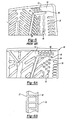
- FIG. 5 shows further features of the tip flag, and the passages 46.
- the tip flag path 50 may be provided with trip strips 52.
- Trip strips 52 are formed on the inner surfaces of the walls 27 and 29, but do not extend across the space between the walls.
- the trip strips are designed to create turbulence in the cooling airflow, thus increasing the heat transfer.
- Trip strips also cannot be used as far toward the trailing edge as pedestals due to manufacturability issues associated with the thinness and fragility of the ceramic core. While the present invention and the prior art problem are discussed with regard to turbine blades, other airfoils or gas turbine components can benefit from this invention. In particular, the invention can extend to stationary vanes.
- FIG. 6A shows an inventive turbine blade 60.
- the tip flag 48 still directs air into a tip flag path 61.
- a pedestal array 62 is provided in the path 61.
- the pedestals 62 extend entirely across the airfoil, and between the walls 27 and 29. The pedestals serve to deliver more heat into the cooling airflow, and thus better address the problem mentioned above.
- a second pedestal array 64 is formed to replace the last several metering holes 46 radially inward the tip flag 48. This pedestal array 64 also removes additional heat from the area and allows for a more robust and manufacturable ceramic core.
- the pedestal array 64 has pedestals of greater diameter than the pedestals 62.
Landscapes
- Engineering & Computer Science (AREA)
- Mechanical Engineering (AREA)
- General Engineering & Computer Science (AREA)
- Chemical & Material Sciences (AREA)
- Combustion & Propulsion (AREA)
- Turbine Rotor Nozzle Sealing (AREA)
Applications Claiming Priority (1)
| Application Number | Priority Date | Filing Date | Title |
|---|---|---|---|
| US11/585,054 US7607891B2 (en) | 2006-10-23 | 2006-10-23 | Turbine component with tip flagged pedestal cooling |
Publications (3)
| Publication Number | Publication Date |
|---|---|
| EP1918522A2 true EP1918522A2 (de) | 2008-05-07 |
| EP1918522A3 EP1918522A3 (de) | 2011-07-20 |
| EP1918522B1 EP1918522B1 (de) | 2016-05-18 |
Family
ID=38739920
Family Applications (1)
| Application Number | Title | Priority Date | Filing Date |
|---|---|---|---|
| EP07254134.5A Active EP1918522B1 (de) | 2006-10-23 | 2007-10-18 | Bauteil für ein Gasturbinentriebwerk |
Country Status (6)
| Country | Link |
|---|---|
| US (1) | US7607891B2 (de) |
| EP (1) | EP1918522B1 (de) |
| JP (1) | JP2008106743A (de) |
| KR (1) | KR20080036510A (de) |
| MX (1) | MX2007013107A (de) |
| SG (1) | SG142227A1 (de) |
Cited By (6)
| Publication number | Priority date | Publication date | Assignee | Title |
|---|---|---|---|---|
| WO2009109462A1 (de) * | 2008-03-07 | 2009-09-11 | Alstom Technology Ltd | Schaufel für eine gasturbine |
| FR2954798A1 (fr) * | 2009-12-31 | 2011-07-01 | Snecma | Aube a ventilation interieure |
| EP3184743A1 (de) * | 2015-12-22 | 2017-06-28 | General Electric Company | Turbinenschaufel mit hinterkantenkühlkreis |
| EP3203026A1 (de) * | 2016-01-22 | 2017-08-09 | United Technologies Corporation | Gasturbinenschaufel mit sockelanordnung |
| FR3096074A1 (fr) * | 2019-05-17 | 2020-11-20 | Safran Aircraft Engines | Aube de turbomachine à bord de fuite ayant un refroidissement amélioré |
| US10900361B2 (en) | 2015-12-04 | 2021-01-26 | Mikro Systems, Inc. | Turbine airfoil with biased trailing edge cooling arrangement |
Families Citing this family (26)
| Publication number | Priority date | Publication date | Assignee | Title |
|---|---|---|---|---|
| US9133715B2 (en) * | 2006-09-20 | 2015-09-15 | United Technologies Corporation | Structural members in a pedestal array |
| US8807945B2 (en) | 2011-06-22 | 2014-08-19 | United Technologies Corporation | Cooling system for turbine airfoil including ice-cream-cone-shaped pedestals |
| US20130243575A1 (en) | 2012-03-13 | 2013-09-19 | United Technologies Corporation | Cooling pedestal array |
| US10100645B2 (en) | 2012-08-13 | 2018-10-16 | United Technologies Corporation | Trailing edge cooling configuration for a gas turbine engine airfoil |
| US9759072B2 (en) | 2012-08-30 | 2017-09-12 | United Technologies Corporation | Gas turbine engine airfoil cooling circuit arrangement |
| US9115590B2 (en) | 2012-09-26 | 2015-08-25 | United Technologies Corporation | Gas turbine engine airfoil cooling circuit |
| EP2964891B1 (de) | 2013-03-05 | 2019-06-12 | Rolls-Royce North American Technologies, Inc. | Komponentenanordnung eines gasturbinenmotors |
| WO2014163698A1 (en) | 2013-03-07 | 2014-10-09 | Vandervaart Peter L | Cooled gas turbine engine component |
| WO2015031057A1 (en) | 2013-08-28 | 2015-03-05 | United Technologies Corporation | Gas turbine engine airfoil crossover and pedestal rib cooling arrangement |
| US9963975B2 (en) * | 2015-02-09 | 2018-05-08 | United Technologies Corporation | Trip strip restagger |
| US10053989B2 (en) | 2015-12-21 | 2018-08-21 | General Electric Company | Cooling circuit for a multi-wall blade |
| US9926788B2 (en) | 2015-12-21 | 2018-03-27 | General Electric Company | Cooling circuit for a multi-wall blade |
| US9976425B2 (en) | 2015-12-21 | 2018-05-22 | General Electric Company | Cooling circuit for a multi-wall blade |
| US10030526B2 (en) | 2015-12-21 | 2018-07-24 | General Electric Company | Platform core feed for a multi-wall blade |
| US10060269B2 (en) | 2015-12-21 | 2018-08-28 | General Electric Company | Cooling circuits for a multi-wall blade |
| US10119405B2 (en) | 2015-12-21 | 2018-11-06 | General Electric Company | Cooling circuit for a multi-wall blade |
| US9932838B2 (en) | 2015-12-21 | 2018-04-03 | General Electric Company | Cooling circuit for a multi-wall blade |
| US10563518B2 (en) | 2016-02-15 | 2020-02-18 | General Electric Company | Gas turbine engine trailing edge ejection holes |
| US10508552B2 (en) * | 2016-04-11 | 2019-12-17 | United Technologies Corporation | Internally cooled airfoil |
| US10221696B2 (en) | 2016-08-18 | 2019-03-05 | General Electric Company | Cooling circuit for a multi-wall blade |
| US10267162B2 (en) | 2016-08-18 | 2019-04-23 | General Electric Company | Platform core feed for a multi-wall blade |
| US10208607B2 (en) | 2016-08-18 | 2019-02-19 | General Electric Company | Cooling circuit for a multi-wall blade |
| US10208608B2 (en) | 2016-08-18 | 2019-02-19 | General Electric Company | Cooling circuit for a multi-wall blade |
| US10227877B2 (en) | 2016-08-18 | 2019-03-12 | General Electric Company | Cooling circuit for a multi-wall blade |
| US10920597B2 (en) * | 2017-12-13 | 2021-02-16 | Solar Turbines Incorporated | Turbine blade cooling system with channel transition |
| US10914178B2 (en) | 2019-03-12 | 2021-02-09 | Raytheon Technologies Corporation | Airfoils having tapered tip flag cavity and cores for forming the same |
Citations (4)
| Publication number | Priority date | Publication date | Assignee | Title |
|---|---|---|---|---|
| US4278400A (en) * | 1978-09-05 | 1981-07-14 | United Technologies Corporation | Coolable rotor blade |
| US5403159A (en) * | 1992-11-30 | 1995-04-04 | United Technoligies Corporation | Coolable airfoil structure |
| US5931638A (en) * | 1997-08-07 | 1999-08-03 | United Technologies Corporation | Turbomachinery airfoil with optimized heat transfer |
| US20050084370A1 (en) * | 2003-07-29 | 2005-04-21 | Heinz-Jurgen Gross | Cooled turbine blade |
Family Cites Families (11)
| Publication number | Priority date | Publication date | Assignee | Title |
|---|---|---|---|---|
| FR2476207A1 (fr) * | 1980-02-19 | 1981-08-21 | Snecma | Perfectionnement aux aubes de turbines refroidies |
| US4474532A (en) * | 1981-12-28 | 1984-10-02 | United Technologies Corporation | Coolable airfoil for a rotary machine |
| US4767268A (en) * | 1987-08-06 | 1988-08-30 | United Technologies Corporation | Triple pass cooled airfoil |
| US5052889A (en) * | 1990-05-17 | 1991-10-01 | Pratt & Whintey Canada | Offset ribs for heat transfer surface |
| DE69328439T2 (de) * | 1992-11-24 | 2000-12-14 | United Technologies Corp | Kühlbare schaufelsstruktur |
| EP0954679B1 (de) * | 1996-06-28 | 2003-01-22 | United Technologies Corporation | Kühlbare schaufelstruktur für eine gasturbine |
| US5975851A (en) * | 1997-12-17 | 1999-11-02 | United Technologies Corporation | Turbine blade with trailing edge root section cooling |
| US6139269A (en) * | 1997-12-17 | 2000-10-31 | United Technologies Corporation | Turbine blade with multi-pass cooling and cooling air addition |
| JPH11223102A (ja) * | 1998-02-04 | 1999-08-17 | Mitsubishi Heavy Ind Ltd | ガスタービン動翼 |
| US6257831B1 (en) * | 1999-10-22 | 2001-07-10 | Pratt & Whitney Canada Corp. | Cast airfoil structure with openings which do not require plugging |
| US7014424B2 (en) * | 2003-04-08 | 2006-03-21 | United Technologies Corporation | Turbine element |
-
2006
- 2006-10-23 US US11/585,054 patent/US7607891B2/en active Active
-
2007
- 2007-08-01 KR KR1020070077401A patent/KR20080036510A/ko not_active Application Discontinuation
- 2007-09-25 SG SG200708820-6A patent/SG142227A1/en unknown
- 2007-10-10 JP JP2007263986A patent/JP2008106743A/ja active Pending
- 2007-10-18 EP EP07254134.5A patent/EP1918522B1/de active Active
- 2007-10-19 MX MX2007013107A patent/MX2007013107A/es not_active Application Discontinuation
Patent Citations (4)
| Publication number | Priority date | Publication date | Assignee | Title |
|---|---|---|---|---|
| US4278400A (en) * | 1978-09-05 | 1981-07-14 | United Technologies Corporation | Coolable rotor blade |
| US5403159A (en) * | 1992-11-30 | 1995-04-04 | United Technoligies Corporation | Coolable airfoil structure |
| US5931638A (en) * | 1997-08-07 | 1999-08-03 | United Technologies Corporation | Turbomachinery airfoil with optimized heat transfer |
| US20050084370A1 (en) * | 2003-07-29 | 2005-04-21 | Heinz-Jurgen Gross | Cooled turbine blade |
Cited By (13)
| Publication number | Priority date | Publication date | Assignee | Title |
|---|---|---|---|---|
| US8182225B2 (en) | 2008-03-07 | 2012-05-22 | Alstomtechnology Ltd | Blade for a gas turbine |
| WO2009109462A1 (de) * | 2008-03-07 | 2009-09-11 | Alstom Technology Ltd | Schaufel für eine gasturbine |
| FR2954798A1 (fr) * | 2009-12-31 | 2011-07-01 | Snecma | Aube a ventilation interieure |
| WO2011080319A1 (fr) * | 2009-12-31 | 2011-07-07 | Snecma | Aube a ventilation interieure |
| CN102713160A (zh) * | 2009-12-31 | 2012-10-03 | 斯奈克玛 | 内部通风叶片 |
| RU2554397C2 (ru) * | 2009-12-31 | 2015-06-27 | Снекма | Лопатка с внутренним вентилированием |
| US10900361B2 (en) | 2015-12-04 | 2021-01-26 | Mikro Systems, Inc. | Turbine airfoil with biased trailing edge cooling arrangement |
| EP3184743A1 (de) * | 2015-12-22 | 2017-06-28 | General Electric Company | Turbinenschaufel mit hinterkantenkühlkreis |
| US9938836B2 (en) | 2015-12-22 | 2018-04-10 | General Electric Company | Turbine airfoil with trailing edge cooling circuit |
| US10570749B2 (en) | 2016-01-22 | 2020-02-25 | United Technologies Corporation | Gas turbine blade with pedestal array |
| EP3203026A1 (de) * | 2016-01-22 | 2017-08-09 | United Technologies Corporation | Gasturbinenschaufel mit sockelanordnung |
| FR3096074A1 (fr) * | 2019-05-17 | 2020-11-20 | Safran Aircraft Engines | Aube de turbomachine à bord de fuite ayant un refroidissement amélioré |
| US11199100B2 (en) | 2019-05-17 | 2021-12-14 | Safran Aircraft Engines | Turbomachine blade with trailing edge having improved cooling |
Also Published As
| Publication number | Publication date |
|---|---|
| KR20080036510A (ko) | 2008-04-28 |
| MX2007013107A (es) | 2009-02-13 |
| EP1918522B1 (de) | 2016-05-18 |
| JP2008106743A (ja) | 2008-05-08 |
| US7607891B2 (en) | 2009-10-27 |
| SG142227A1 (en) | 2008-05-28 |
| US20080095636A1 (en) | 2008-04-24 |
| EP1918522A3 (de) | 2011-07-20 |
Similar Documents
| Publication | Publication Date | Title |
|---|---|---|
| EP1918522B1 (de) | Bauteil für ein Gasturbinentriebwerk | |
| US7775768B2 (en) | Turbine component with axially spaced radially flowing microcircuit cooling channels | |
| US8172533B2 (en) | Turbine blade internal cooling configuration | |
| EP1959097B1 (de) | Prallkühlung für Verkleidung und Innenteil einer Gasturbinenmotorschaufel | |
| US9206697B2 (en) | Aerofoil cooling | |
| US7575414B2 (en) | Turbine nozzle with trailing edge convection and film cooling | |
| US8177507B2 (en) | Triangular serpentine cooling channels | |
| EP2888462B1 (de) | Innenkühlungsfunktionen für eine gasturbinenmotorschaufel | |
| US10830049B2 (en) | Leading edge hybrid cavities and cores for airfoils of gas turbine engine | |
| US10247099B2 (en) | Pedestals with heat transfer augmenter | |
| US8297925B2 (en) | Aerofoil configuration | |
| US7726944B2 (en) | Turbine blade with improved durability tip cap | |
| EP2551458A2 (de) | Schaufelkühl- und -abdichtsystem | |
| EP3190262A1 (de) | Kühlkanal für austrittskante einer turbinenschaufel | |
| US10794194B2 (en) | Staggered core printout | |
| EP3647544A1 (de) | Gegühltes gasturbinen leitschaufelprofil | |
| US20180051569A1 (en) | Engine component with porous section | |
| US10253636B2 (en) | Flow exchange baffle insert for a gas turbine engine component | |
| GB2577199A (en) | Blade for a turbomachine turbine, comprising internal passages for circulating cooling air |
Legal Events
| Date | Code | Title | Description |
|---|---|---|---|
| PUAI | Public reference made under article 153(3) epc to a published international application that has entered the european phase |
Free format text: ORIGINAL CODE: 0009012 |
|
| AK | Designated contracting states |
Kind code of ref document: A2 Designated state(s): AT BE BG CH CY CZ DE DK EE ES FI FR GB GR HU IE IS IT LI LT LU LV MC MT NL PL PT RO SE SI SK TR |
|
| AX | Request for extension of the european patent |
Extension state: AL BA HR MK RS |
|
| PUAL | Search report despatched |
Free format text: ORIGINAL CODE: 0009013 |
|
| AK | Designated contracting states |
Kind code of ref document: A3 Designated state(s): AT BE BG CH CY CZ DE DK EE ES FI FR GB GR HU IE IS IT LI LT LU LV MC MT NL PL PT RO SE SI SK TR |
|
| AX | Request for extension of the european patent |
Extension state: AL BA HR MK RS |
|
| 17P | Request for examination filed |
Effective date: 20120118 |
|
| AKX | Designation fees paid |
Designated state(s): DE GB |
|
| GRAP | Despatch of communication of intention to grant a patent |
Free format text: ORIGINAL CODE: EPIDOSNIGR1 |
|
| INTG | Intention to grant announced |
Effective date: 20160208 |
|
| GRAS | Grant fee paid |
Free format text: ORIGINAL CODE: EPIDOSNIGR3 |
|
| GRAA | (expected) grant |
Free format text: ORIGINAL CODE: 0009210 |
|
| AK | Designated contracting states |
Kind code of ref document: B1 Designated state(s): DE GB |
|
| REG | Reference to a national code |
Ref country code: GB Ref legal event code: FG4D |
|
| REG | Reference to a national code |
Ref country code: DE Ref legal event code: R096 Ref document number: 602007046346 Country of ref document: DE |
|
| RAP2 | Party data changed (patent owner data changed or rights of a patent transferred) |
Owner name: UNITED TECHNOLOGIES CORPORATION |
|
| REG | Reference to a national code |
Ref country code: DE Ref legal event code: R097 Ref document number: 602007046346 Country of ref document: DE |
|
| PLBE | No opposition filed within time limit |
Free format text: ORIGINAL CODE: 0009261 |
|
| STAA | Information on the status of an ep patent application or granted ep patent |
Free format text: STATUS: NO OPPOSITION FILED WITHIN TIME LIMIT |
|
| 26N | No opposition filed |
Effective date: 20170221 |
|
| REG | Reference to a national code |
Ref country code: DE Ref legal event code: R082 Ref document number: 602007046346 Country of ref document: DE Representative=s name: SCHMITT-NILSON SCHRAUD WAIBEL WOHLFROM PATENTA, DE |
|
| REG | Reference to a national code |
Ref country code: DE Ref legal event code: R082 Ref document number: 602007046346 Country of ref document: DE Representative=s name: SCHMITT-NILSON SCHRAUD WAIBEL WOHLFROM PATENTA, DE Ref country code: DE Ref legal event code: R081 Ref document number: 602007046346 Country of ref document: DE Owner name: UNITED TECHNOLOGIES CORP. (N.D.GES.D. STAATES , US Free format text: FORMER OWNER: UNITED TECHNOLOGIES CORPORATION, HARTFORD, CONN., US |
|
| REG | Reference to a national code |
Ref country code: DE Ref legal event code: R081 Ref document number: 602007046346 Country of ref document: DE Owner name: RAYTHEON TECHNOLOGIES CORPORATION (N.D.GES.D.S, US Free format text: FORMER OWNER: UNITED TECHNOLOGIES CORP. (N.D.GES.D. STAATES DELAWARE), FARMINGTON, CONN., US |
|
| P01 | Opt-out of the competence of the unified patent court (upc) registered |
Effective date: 20230519 |
|
| PGFP | Annual fee paid to national office [announced via postgrant information from national office to epo] |
Ref country code: GB Payment date: 20230920 Year of fee payment: 17 |
|
| PGFP | Annual fee paid to national office [announced via postgrant information from national office to epo] |
Ref country code: DE Payment date: 20230920 Year of fee payment: 17 |