EP1918145A2 - Structure of commercial vehicle with roof columns, including roof column and method for manufacturing roof column - Google Patents
Structure of commercial vehicle with roof columns, including roof column and method for manufacturing roof column Download PDFInfo
- Publication number
- EP1918145A2 EP1918145A2 EP07020768A EP07020768A EP1918145A2 EP 1918145 A2 EP1918145 A2 EP 1918145A2 EP 07020768 A EP07020768 A EP 07020768A EP 07020768 A EP07020768 A EP 07020768A EP 1918145 A2 EP1918145 A2 EP 1918145A2
- Authority
- EP
- European Patent Office
- Prior art keywords
- roller guide
- profile
- roof
- roller
- roof rail
- Prior art date
- Legal status (The legal status is an assumption and is not a legal conclusion. Google has not performed a legal analysis and makes no representation as to the accuracy of the status listed.)
- Withdrawn
Links
Images

Classifications
-
- B—PERFORMING OPERATIONS; TRANSPORTING
- B60—VEHICLES IN GENERAL
- B60J—WINDOWS, WINDSCREENS, NON-FIXED ROOFS, DOORS, OR SIMILAR DEVICES FOR VEHICLES; REMOVABLE EXTERNAL PROTECTIVE COVERINGS SPECIALLY ADAPTED FOR VEHICLES
- B60J5/00—Doors
- B60J5/04—Doors arranged at the vehicle sides
- B60J5/06—Doors arranged at the vehicle sides slidable; foldable
- B60J5/062—Doors arranged at the vehicle sides slidable; foldable for utility vehicles or public transport
- B60J5/065—Doors arranged at the vehicle sides slidable; foldable for utility vehicles or public transport with non-rigid elements, e.g. side curtains
Definitions
- the invention relates to a commercial vehicle body with roof rails, a roof rail for such a commercial vehicle body and a method for producing a roof rail.
- roof bars are formed by extruded aluminum profiles, in the cross section advantageously guideways for z.
- the roof struts are supported at opposite ends on a front body and on vertical tail stanchions vertically. Additional stanchions in the longitudinal direction of the roof rails can be designed for lateral loading possibilities as slides, so that the roof bars are temporarily supported only at the opposite ends.
- the roof struts should, in order to restrict a light rectangular profile of the cargo space as little as possible, protrude at the corners only by a small amount in the cargo space.
- Common profiles are in particular so-called standard curtain sider profiles such.
- a third roller guide for vertical support of hoops of a folding top assembly is above the first roller guide and a fourth roller guide for horizontal support of the hoop is disposed above the second roller guide.
- first and the second roller guide are arranged vertically spaced from each other and the side curtain is guided by the above arranged first roller guide on the bottom arranged second roller guide over.
- Such spar profiles allow a large cargo space width and cargo space height, but have on the vertical profile leg portions of low torsional stiffness.
- Such spar profiles are z. B. from the DE 100 35 103 A1 , of the DE 102 52 461 A1 or the DE 197 56 617 A1 known.
- profiles with a higher design for lateral loading must also be raised higher.
- the present invention has for its object to provide a commercial vehicle body with roof beams and a roof spar for this purpose, which are further improved, in particular with regard to the spar cross-section.
- both the first rollers on the tarpaulin holders and the second rollers on stake holders are each designed as rollers arranged only on one side of the respective holder.
- a third and a fourth roller guide for vertical or horizontal support of a bow arrangement are provided in a conventional manner.
- the profile cross-section over the first and the second roller guide can advantageously be designed to be multi-walled.
- the formation of a chamber closed in cross section can be provided laterally from a third roller guide located above the first roller guide.
- the chamber may have a substantially rectangular cross-section.
- the chamber is advantageously above the second roller guide.
- One of the third roller guide laterally facing away from the chamber wall preferably forms with a side facing away from the first roller guide wall of the second roller guide a continuous vertical wall surface, which assigns in the commercial vehicle body of the vehicle center.
- the chamber advantageously extends to the top of the profile.
- the roof spar contains a profile body made of aluminum, which is integrally connected in cross-section, and a stabilizing element, which increases the bending stiffness of the roof spar, and which is connected to the latter and extends in the longitudinal direction of the profile body.
- the stabilizing element is advantageously connected substantially over its entire length with the profile body.
- the stiffening element may advantageously contribute significantly to the flexural rigidity of the connected profile, advantageously at least 25%, in particular at least 35%, preferably at least 45% of the total bending stiffness of the connected profile, in particular the bending stiffness against vertical deflection of the roof rail in its installed position.
- the stiffening element may advantageously consist of plastic or in particular of steel.
- the stiffening element is arranged in the above the second roller guide chamber and is preferably formed as a steel profile, in particular steel tube.
- the present in linear form steel profile is inserted into the chamber of the present also in linear form profile body in the longitudinal direction and that subsequently the combined roof rail profile of profile body and stabilizing element of the linear Shape in a curved shape, z. B. by rolling, is transformed, wherein profile body and stabilizing element abut each other at least on a part of the inner wall surfaces of the chamber.
- a compound profile body and stabilizing element can also be done by friction, elastic tension, selective joining elements, positive locking, clinching, gluing, welding or the like.
- the combination of profile body and stabilizing element is advantageously such that a deflection of the profile body is coupled to a deflection of the stabilizing element in substantially the same degree and vice versa.
- the roof rail according to the invention can advantageously replace all of the mentioned common roof rail profiles without disadvantages in the functions for loading space dimensions or stability of the said known roof rail profiles and beyond also for full tarpaulin sliding roofs or the so-called Hamburg roof.
- the universal usability provides significant economic benefits in procurement and warehousing.
- a commercial vehicle body as part of a towing vehicle or a trailer is schematically outlined in side view.
- a loading space RA above a floor group BO of the vehicle is bounded above by roof tarpaulin DP and laterally by longitudinally collapsible side tarpaulins SP, which can be pushed together in a direction of travel FR extending longitudinal direction x of an xyz coordinate system drawn towards the front wall VW out.
- the roof tarpaulin DP is displaceably guided by means of brackets (not shown in detail) along two roof rails HO which are essentially laterally delimiting the cargo space RA, in particular by means of roller arrangements at the ends of the bow and cooperating roller tracks in the roof rails HO.
- the displacement of the side tarpaulins SP also typically takes place via rollers guided in guideways of the roof pillars by a plurality of tarpaulin holders.
- the spars HO are supported vertically at their opposite ends on the front wall VW and on the rear stanchions HR.
- the roof rails HO are also vertically supported in intermediate positions on additional stanchions against the bottom group BO, these intermediate stanchions are often designed for improved lateral loading as sliding, which are releasably and longitudinally displaceable from a closed position in defined longitudinal positions.
- a first sliding tongue SR1 is shown displaced in its intended for driving position and a sliding tongue SR2 to achieve an enlarged lateral opening in the longitudinal direction.
- the slides are slidably guided over guided in other guideways of the roof rails rollers.
- the roof rails HO are typically designed to be curved against an exactly linear shape and, in the unloaded state, exhibit a curvature directed upward in the z direction between their opposite ends a drawn with a broken line as a reference straight connection of the bar ends.
- Fig. 1 is not to scale.
- the relative measures are skewed.
- the relative curvature of the roof struts is much lower than in the sketch and is for example at a length of the roof struts of 13 m only about 100-300 mm.
- the roof rails HO are typically designed as extruded aluminum profiles, in the cross sections of the roller tracks for the bow, the tarpaulin holder and the stanchion holder are already formed.
- the roof struts should, in order to affect the clear profile of the hold RA as little as possible, protrude at the corners only by a small amount in the hold and require little aluminum in the interest of light weight and low material costs.
- the stability of the spars should be reliably guaranteed under the typical loads, the current profiles are always a compromise between the various requirements.
- Typical known profiles are the standard Curtain Sider profile with adjacent roller guides for sliding tongue and side tarpaulin and z , B. referred to as mega-profiles high profiles with superimposed roller guides for pushers and side tarpaulin.
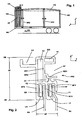
- a preferred profile cross-section of such a roof rail is sketched in cross-section in a yz-plane perpendicular to the longitudinal direction of a roof rail in the installation position.
- the roof spar is preferably in ge per se common type of an aluminum profile body PK2.
- the cross-section of the profile body shows in such profiles in a known per se, a first roller guide F1 with a first roller tread LP for first rollers PR a Side cover assembly connected to the rollers PR via the tarpaulin holder PH, and a second roller guide F2 having a second roller tread LR for second rollers RR of a slider assembly having their slides connected to the rollers RR via stanchions RH.
- the roller treads LP and LR are formed as substantially horizontal extensions of wall legs WF1 of the first roller guide F1 and W12 of the second roller guide F2.
- the roller treads can be curved.
- the two roller guides F1, F2 are separated from each other by the wall leg W12 as an intermediate wall, wherein the intermediate wall can also serve as a limit for a lateral displacement of the guided rollers with the stanchion holders RH.
- the rollers RP on the tarpaulin holders are secured against undesired displacement in the lateral direction y by a laterally outer wall limb WF1.
- the profile cross-section also shows in a conventional manner, a third roller guide LV for the vertical support of a not shown with bowing arrangement and a fourth roller guide LH for horizontal support of such a Spriegelan ever.
- the profile body PK2 has a height HP between an upper boundary plane OE and a lower boundary plane UE.
- the height HP is advantageously less than 110 mm.
- the third roller guide LV is arranged above the first roller guide F1.
- a closed, in particular substantially rectangular, first chamber K1 is advantageously formed in the profile cross section.
- a second chamber K2 is formed, which preferably extends up to the upper boundary plane OE.
- the second chamber K2 forms with its the third roller guide LV and the first chamber K1 facing first vertical wall WK1 and this spaced opposite, the vehicle center, in Fig. 2 left, facing vertical wall WK2 an element within the profile cross-section with high bending stiffness against vertical deflection.
- the horizontal wall sections WZH in the upper boundary of the roller guides F1, F2 and the horizontal wall surface WO at the upper boundary plane OE form elements with high bending stiffness against horizontal deflection of the profile.
- the clear inner cross section of the second chamber K2 is preferably at least twice as large in the vertical extent as in the horizontal extension.
- the vehicle center facing vertical wall WK2 of the second chamber and the vehicle center facing wall leg WF2 the second roller guide preferably form a continuous vertical wall surface, which passes up to the fourth roller guide LH and preferably further up to the upper boundary plane OE is continued.
- the fourth roller guide LH is designed in the sketched preferred example as the vehicle center of the vertical wall surface WK2 projecting.
- a receptacle FD is still formed for a hanging over the upper edge of the tarpaulin sealing membrane and a chamber K3 without further significant function.
- the guides F1 and F2 side by side y are arranged at substantially the same height and each have only one roller tread LP and LR and that the roller assemblies for a side tarpaulin arrangement and a Schiebereptan extract both on the tarpaulin holders PH and the post holders RH only after one side, offset in the preferred example outlined in the direction of the vehicle center against the holder, roles RP or RR wear.
- the width BP of the profile body in the region below the fourth roller guide LH can be kept low, in particular less than 40 mm, preferably approximately 35 mm.
- the entire height HP of the profile cross section can be kept small, in particular smaller than 110 mm.
- a roof rail profile is outlined with a profile body PK3 as aluminum extruded profile, in which the essential features of the profile of Fig. 2, in particular the arrangement of the two roller guides F1 and F2 side by side y next to each other, training only ever a roller tread LP and LR in the two roller guides F1, F2 and the arrangement of rollers RP and RR on only one side of the tarpaulin holder PH and the stanchion RH shows.
- the roller treads LP and LR are manufactured det in this example as protruding in opposite side direction horizontal leg at the lower end of a central web MS , which also forms a partition between the two roller guides F1, F2.
- the roof spar profile with the sketched in Fig. 2 cross-section shows in itself by the advantageous arrangement of the individual elements a high bending stiffness against deflection in both the horizontal and in the vertical direction.
- an additional, extending in the longitudinal direction of the roof rail and connected thereto, preferably connected substantially over the entire length of the spar stabilizing element may be preferably provided from a different material.
- a steel tube SR in the chamber K2 is provided for this purpose for the example of the profile cross-section according to FIG. 2, which has a substantially rectangular cross section adapted to the chamber cross section of the chamber K2.
- the contribution of the stabilizing element SR to the bending stiffness of the entire hollow profile against bending in the vertical direction is advantageously at least 25%, in particular at least 35%, preferably at least 45% of the bending stiffness of the composite roof spar profile, in particular against vertical deflection.
- the stabilizing element SR which is linear in the x direction, is preferably linear in the x direction
- Profile body PK4 inserted into its chamber K2 and by subsequent forming of the composite roof rail from the linear in the x-direction shape in the sketched in Fig. 1 curved shape of the profile body PK4 and the stabilizing element SR are deformed together and remain firmly connected to each other, in particular Bias in the vertical direction on at least part surfaces of the inner wall surfaces of the chamber K2 to each other.
- the stabilizing element SR may also have other shapes than those outlined.
- the chamber K2 can also be subdivided in the vertical direction, but the vertical cross-section through which the stabilizing element is inserted is particularly advantageous due to the large, continuous vertical dimension.
- Profile body and stabilizing element can also be connected to each other in other ways.
- a further profile variant is outlined with another embodiment of a Stabilsticianselements.
- the roller treads LP and LR of the first roller guide F1 and the second roller guide F2 are each carried out on horizontal extensions of wall legs WF1 and WF2, which are each facing outwardly with respect to the juxtaposed roller guide and whose horizontal extensions are directed to the vertical center plane of the profile ,
- a vertical intermediate web ZS which faces downwards from the upper boundary wall WZH of the roller guides, forms a partition wall between the two roller guides and can also serve as a boundary against displacement of the rollers with the holders in the y-direction.
- the other features and advantages of the roller guides of Fig. 2 and Fig. 3 are also obtained in this example.
- the chambers K2 and K3 of the example according to FIG. 2 are in the profile body PK5 of the example according to FIG. 5 in FIG same as in the example of FIG. 3 to a single chamber summarized.
- the stabilizing element SS filling of the chamber K2 with a stiffening material is provided in the example according to FIG. 5, which adjusts to the entire, non-rectangular chamber cross section.
- the stabilizing element SS consists of a plastic, which is introduced into the profile chamber K2 in flexible or flowable form and cured therein, wherein the curing may precede a foaming.
- the plastic material may be added for increased tensile strength fiber elements in the manner of a glass fiber or carbon fiber reinforced plastic.
- stiffening elements SR according to FIG. 4 and SS according to FIG. 5 can also be advantageously combined in such a way that the interior of the stiffening element SR is filled by a material of a stiffening element SS according to FIG. 5 and thereby the shape of the stiffening element SR is stabilized ,
- FIG. 6 shows a further variant of a profile cross section of a profile body PK6 as an aluminum extruded profile in conjunction with a further variant of a stiffening profile.
- the fourth roller guide LH of the preceding examples arranged towards the vehicle center is replaced by a fourth roller guide LA, which is arranged on the side of the chamber K2 of the profile body facing away from the vehicle center.
- the first chamber K1 of the previous profile examples is thereby eliminated.
- the roller treads LP and LR are similar to the variant of FIG.
- the different profile cross-sections and the various stabilizing elements can, insofar as the features do not contradict themselves, also be realized in a different combination.
- the materials for the individual components are not limited to the aforementioned preferred examples.
- the stabilizing element SR of FIG. 5 may also have a different shape than the outlined tube shape, for example, an H-shape or a double-T shape.
- the lateral securing of the tarpaulin holder PH with rollers RP in the first guides or the stanchion holder RH with rollers RP in the second guides serving vertical wall leg or webs without lateral extensions with roller treads are in their vertical extension down to a lesser extent than advantageously limited the vertical extent of the roller guides, but advantageously enough at least up to the upper ends of the respective holder, so that the limiting in the y direction guide by conditioning the holder takes place on these wall legs or webs and the holder bent below the roller axes of the roller tracks away can run.
- FIG. 2 serving as a partition wall legs W12 at the lower end slightly inclined from the stanchion holders RH formed inclined.
Abstract
Description
Die Erfindung betrifft einen Nutzfahrzeugaufbau mit Dachholmen, einen Dachholm für einen solchen Nutzfahrzeugaufbau und ein Verfahren zur Herstellung eines Dachholms.The invention relates to a commercial vehicle body with roof rails, a roof rail for such a commercial vehicle body and a method for producing a roof rail.
Nutzfahrzeugaufbauten sind in einer Variante gebräuchlich, bei welcher ein durch eine Dachanordnung, insbesondere ein Planendach abgedeckter Laderaum im Dachbereich zwei in Fahrzeuglängsrichtung verlaufende Dachholme aufweist. In bevorzugter Ausführung sind die Dachholme durch Aluminium-Strangpressprofile gebildet, in deren Querschnitt vorteilhafterweise Führungsbahnen für z. B. Spriegel eines Faltdaches, Rollen einer Seitenplanenanordnung, Rollen von Schieberungen ausgebildet sein können. Durch die Ausführung als Aluminium-Strangpressprofile können auf einfache Weise mehrere Funktionen in die Holme integriert und das Gewicht im Interesse eines höheren Ladegewichts niedrig gehalten werden. Die Dachholme sind an entgegen gesetzten Enden an einem Frontaufbau und an ortsfesten Heckrungen vertikal abgestützt. Zusätzliche Rungen im Längsverlauf der Dachholme können für seitliche Beladungsmöglichkeiten als Schieberungen ausgeführt sein, so dass die Dachholme zeitweise nur an den entgegen gesetzten Enden abgestützt sind.Commercial vehicle superstructures are customary in a variant in which a cargo space covered by a roof arrangement, in particular a canopy, has two roof pillars extending in the vehicle longitudinal direction in the roof area. In a preferred embodiment, the roof bars are formed by extruded aluminum profiles, in the cross section advantageously guideways for z. B. Spriegel a folding roof, rolling a side canvas arrangement, roles of pushers can be formed. Due to the design as aluminum extruded profiles, several functions can be easily integrated into the spars and the weight can be kept low in the interest of a higher load weight. The roof struts are supported at opposite ends on a front body and on vertical tail stanchions vertically. Additional stanchions in the longitudinal direction of the roof rails can be designed for lateral loading possibilities as slides, so that the roof bars are temporarily supported only at the opposite ends.
Die Dachholme sollen, um ein lichtes Rechteck-Profil des Laderaums möglichst wenig einzuschränken, an den Ecken nur um ein geringes Maß in den Laderaum ragen. Gebräuchliche Profile sind insbesondere sogenannte Standard-Curtain-Sider-Profile, wie z. B. in der
In anderer gebräuchlicher Anordnung sind die erste und die zweite Rollenführung vertikal voneinander beabstandet angeordnet und die Seitenplane ist von der oben angeordneten ersten Rollenführung an der unten angeordneten zweiten Rollenführung vorbei geführt. Derartige Holmprofile ermöglichen eine große Laderaumbreite und Laderaumhöhe, weisen aber an dem vertikalen Profilschenkel Abschnitte geringer Verwindungssteifigkeit auf. Derartige Holmprofile sind z. B. aus der
Der vorliegenden Erfindung liegt die Aufgabe zugrunde, einen Nutzfahrzeugaufbau mit Dachholmen und einen Dachholm hierfür anzugeben, welche insbesondere hinsichtlich des Holmquerschnitts weiter verbessert sind.The present invention has for its object to provide a commercial vehicle body with roof beams and a roof spar for this purpose, which are further improved, in particular with regard to the spar cross-section.
Erfindungsgemäße Lösungen sind in den unabhängigen Ansprüchen beschrieben. Die abhängigen Ansprüche enthalten vorteilhafte Ausgestaltungen und Weiterbildungen der Erfindung.Solutions according to the invention are described in the independent claims. The dependent claims contain advantageous refinements and developments of the invention.
Durch die Ausbildung der ersten und der zweiten auf gleicher Höhe nebeneinander liegenden Rollenführung mit jeweils nur einer Rollenlauffläche ergibt sich auf Höhe der ersten und zweiten Rollenführung eine besonders geringe Baubreite des Dachholmprofils, welche vorteilhafterweise geringer als 40 mm, insbesondere ungefähr gleich 35 mm ist. Entsprechend der nur einen Rollenlauffläche der ersten und der zweiten Rollenführung in dem Dachholmprofil sind sowohl die ersten Rollen an Planenhaltern als auch die zweiten Rollen an Rungenhaltern jeweils als nur auf einer Seite der jeweiligen Halter angeordnete Rollen ausgeführt. Vorzugsweise sind in an sich bekannter Art eine dritte und eine vierte Rollenführung für vertikale bzw. horizontale Abstützung einer Spriegelanordnung vorgesehen.Due to the formation of the first and the second juxtaposed roller guide with only one roller tread at the level of the first and second roller guide results in a particularly small width of the roof rail profile, which advantageously less than 40 mm, in particular is about 35 mm. Corresponding to the only one roller running surface of the first and the second roller guide in the roof rail profile, both the first rollers on the tarpaulin holders and the second rollers on stake holders are each designed as rollers arranged only on one side of the respective holder. Preferably, a third and a fourth roller guide for vertical or horizontal support of a bow arrangement are provided in a conventional manner.
Durch die Anordnung der ersten und der zweiten Rollenanordnung nebeneinander kann vorteilhafterweise der Profilquerschnitt über der ersten und der zweiten Rollenführung mehrwandig aufgebaut sein. Insbesondere kann die Ausbildung einer im Querschnitt geschlossenen Kammer seitlich von einer oberhalb der ersten Rollenführung liegenden dritten Rollenführung vorgesehen sein. Die Kammer kann insbesondere einen im wesentlichen rechteckigen Querschnitt aufweisen. Die Kammer liegt vorteilhafterweise über der zweiten Rollenführung. Eine der dritten Rollenführung seitlich abgewandte Kammerwand bildet vorzugsweise mit einer der ersten Rollenführung abgewandten Wand der zweiten Rollenführung eine durchgehende vertikale Wandfläche, welche in dem Nutzfahrzeugaufbau der Fahrzeugmitte zuweist. Die Kammer erstreckt sich vorteilhafterweise bis zur Oberseite des Profils.By arranging the first and the second roller arrangement next to one another, the profile cross-section over the first and the second roller guide can advantageously be designed to be multi-walled. In particular, the formation of a chamber closed in cross section can be provided laterally from a third roller guide located above the first roller guide. In particular, the chamber may have a substantially rectangular cross-section. The chamber is advantageously above the second roller guide. One of the third roller guide laterally facing away from the chamber wall preferably forms with a side facing away from the first roller guide wall of the second roller guide a continuous vertical wall surface, which assigns in the commercial vehicle body of the vehicle center. The chamber advantageously extends to the top of the profile.
In besonders vorteilhafter Weiterbildung kann vorgesehen sein, dass der Dachholm einen im Querschnitt einstückig zusammenhängenden Profilkörper aus Aluminium und ein mit diesem verbundenes, sich in Längsrichtung des Profilkörpers erstreckendes Stabilisierungselement, welches die Biegesteifigkeit des Dachholms erhöht, enthält. Das Stabilisierungselement ist vorteilhafterweise im wesentlichen über seine gesamte Länge mit dem Profilkörper verbunden. Hierdurch können vorteilhafterweise die mehreren Rollenführungen vollständig oder überwiegend in dem Aluminium-Profilkörper als einem Aluminium-Strangpressprofil ausgebildet sein und das Aussteifungselement kann vorteilhafterweise einen wesentlichen Anteil zur Biegesteifigkeit des verbundenen Profils, vorteilhafterweise wenigstens 25 %, insbesondere wenigstens 35 %, vorzugsweise wenigstens 45 % der gesamten Biegesteifigkeit des verbundenen Profils, insbesondere der Biegesteifigkeit gegen vertikale Durchbiegung des Dachholms in dessen Einbaulage beitragen.In a particularly advantageous development, it can be provided that the roof spar contains a profile body made of aluminum, which is integrally connected in cross-section, and a stabilizing element, which increases the bending stiffness of the roof spar, and which is connected to the latter and extends in the longitudinal direction of the profile body. The stabilizing element is advantageously connected substantially over its entire length with the profile body. This advantageously allows the plurality of roller guides completely or predominantly in the aluminum profile body as an aluminum extruded profile be formed and the stiffening element may advantageously contribute significantly to the flexural rigidity of the connected profile, advantageously at least 25%, in particular at least 35%, preferably at least 45% of the total bending stiffness of the connected profile, in particular the bending stiffness against vertical deflection of the roof rail in its installed position.
Das Aussteifungselement kann vorteilhafterweise aus Kunststoff oder insbesondere aus Stahl bestehen. In bevorzugter Ausführung ist das Aussteifungselement in der oberhalb der zweiten Rollenführung liegenden Kammer angeordnet und ist vorzugsweise als Stahlprofil, insbesondere Stahlrohr ausgebildet. Zur Herstellung des Dachholms mit dem verbunden Stahlprofil als Aussteifungselement kann dabei vorteilhafterweise vorgesehen sein, dass das in linearer Form vorliegende Stahlprofil in die Kammer des gleichfalls in linearer Form vorliegenden Profilkörpers in Längsrichtung eingeschoben wird und dass nachfolgend das kombinierte Dachholmprofil aus Profilkörper und Stabilisierungselement aus der linearen Form in eine gekrümmte Form, z. B. durch Walzen, umgeformt wird, wobei Profilkörper und Stabilisierungselement zumindest an einem Teil der Innenwandflächen der Kammer aneinander anliegen.The stiffening element may advantageously consist of plastic or in particular of steel. In a preferred embodiment, the stiffening element is arranged in the above the second roller guide chamber and is preferably formed as a steel profile, in particular steel tube. To produce the roof rail with the connected steel profile as a stiffening element can advantageously be provided that the present in linear form steel profile is inserted into the chamber of the present also in linear form profile body in the longitudinal direction and that subsequently the combined roof rail profile of profile body and stabilizing element of the linear Shape in a curved shape, z. B. by rolling, is transformed, wherein profile body and stabilizing element abut each other at least on a part of the inner wall surfaces of the chamber.
Eine Verbindung von Profilkörper und Stabilisierungselement kann auch durch Reibung, elastische Verspannung, punktueller Fügeelemente, Formschluss, Clinchen, Kleben, Schweißen oder ähnliches erfolgen. Die Verbindung von Profilkörper und Stabilisierungselement ist vorteilhafterweise derart, dass eine Durchbiegung des Profilkörpers mit einer Durchbiegung des Stabilisierungselements in im wesentlichen gleichem Maß gekoppelt ist und umgekehrt.A compound profile body and stabilizing element can also be done by friction, elastic tension, selective joining elements, positive locking, clinching, gluing, welding or the like. The combination of profile body and stabilizing element is advantageously such that a deflection of the profile body is coupled to a deflection of the stabilizing element in substantially the same degree and vice versa.
Bei geringeren Anforderungen an die Biegesteifigkeit z. B. bei geringeren Längen von Dachholmen oder Dachholmabschnitten kann auf das zusätzliche Stabilisierungselement verzichtet werden.For lower demands on the bending stiffness z. B. at shorter lengths of roof struts or roof stringer sections can be dispensed with the additional stabilizing element.
Der erfindungsgemäße Dachholm kann vorteilhafterweise alle der genannten gebräuchlichen Dachholmprofile ohne Nachteile bei den Funktionen für Laderaummaße oder Stabilität die genannten bekannten Dachholmprofile ersetzen und darüber hinaus auch für Vollplanen-Schiebeverdecke oder das sogenannte Hamburger Dach eingesetzt werden. Die universelle Verwendbarkeit ergibt erhebliche wirtschaftliche Vorteile bei Beschaffung und Lagerhaltung.The roof rail according to the invention can advantageously replace all of the mentioned common roof rail profiles without disadvantages in the functions for loading space dimensions or stability of the said known roof rail profiles and beyond also for full tarpaulin sliding roofs or the so-called Hamburg roof. The universal usability provides significant economic benefits in procurement and warehousing.
Die Erfindung ist nachfolgend anhand bevorzugter Ausführungsbeispiele unter Bezugnahme auf die Abbildungen noch eingehend veranschaulicht. Dabei zeigt:
- Fig. 1
- einen Nutzfahrzeugaufbau in Seitenansicht,
- Fig. 2
- ein vorteilhaftes Dachholmprofil,
- Fig. 3
- ein weiteres vorteilhaftes Dachholmprofil,
- Fig. 4
- das Dachholmprofil nach Fig. 2 mit Stabilisierungselement,
- Fig. 5
- ein weiteres Dachholmprofil mit Stabilisierungselement,
- Fig. 6
- eine Abwandlung des Dachholmprofils nach Fig. 3 mit Stabilisierungselement.
- Fig. 1
- a commercial vehicle body in side view,
- Fig. 2
- an advantageous roof spar profile,
- Fig. 3
- another advantageous roof spar profile,
- Fig. 4
- the roof spar profile according to FIG. 2 with stabilizing element,
- Fig. 5
- another roof spar profile with stabilizing element,
- Fig. 6
- a modification of the roof rail profile of Fig. 3 with stabilizing element.
In Fig. 1 ist in Seitenansicht schematisch ein Nutzfahrzeugaufbau als Teil eines Zugfahrzeugs oder eines Anhängers skizziert. Ein Laderaum RA über einer Bodengruppe BO des Fahrzeugs ist oben durch Dachplane DP und seitlich durch in Längsrichtung zusammenschiebbare Seitenplanen SP begrenzt, die in einer in Fahrtrichtung FR verlaufenden Längsrichtung x eines mit eingezeichneten xyz-Koordinatensystems zur Vorderwand VW hin zusammenschiebbar sind. Die Dachplane DP ist über nicht im Detail dargestellte Spriegel entlang von zwei im Dachbereich den Laderaum RA im wesentlichen seitlich begrenzenden Dachholmen HO verschiebbar geführt, insbesondere mittels Rollenanordnungen an den Enden der Spriegel und mit diesen zusammenwirkenden Rollenlaufbahnen in den Dachholmen HO. Die Verschiebung der Seitenplanen SP erfolgt typischerweise gleichfalls über in Führungsbahnen der Dachholme geführte Rollen von einer Mehrzahl von Planenhaltern. Die Holme HO sind an ihren entgegen gesetzten Enden an der Vorderwand VW und an Heckrungen HR vertikal abgestützt. Die Dachholme HO sind ferner in Zwischenpositionen über zusätzliche Rungen gegen die Bodengruppe BO vertikal abgestützt, wobei diese Zwischenrungen für verbesserte seitliche Beladung häufig als Schieberungen ausgeführt sind, welche aus einer geschlossenen Stellung in definierten Längspositionen lösbar und in Längsrichtung verschiebbar sind. In der Skizze nach Fig. 1 ist eine erste Schieberunge SR1 an ihrer für Fahrbetrieb vorgesehenen Position und eine Schieberunge SR2 zur Erzielung einer vergrößerten seitlichen Öffnung in Längsrichtung verschoben eingezeichnet. Die Schieberungen sind über in weiteren Führungsbahnen der Dachholme geführte Rollen verschiebbar geführt.In Fig. 1, a commercial vehicle body as part of a towing vehicle or a trailer is schematically outlined in side view. A loading space RA above a floor group BO of the vehicle is bounded above by roof tarpaulin DP and laterally by longitudinally collapsible side tarpaulins SP, which can be pushed together in a direction of travel FR extending longitudinal direction x of an xyz coordinate system drawn towards the front wall VW out. The roof tarpaulin DP is displaceably guided by means of brackets (not shown in detail) along two roof rails HO which are essentially laterally delimiting the cargo space RA, in particular by means of roller arrangements at the ends of the bow and cooperating roller tracks in the roof rails HO. The displacement of the side tarpaulins SP also typically takes place via rollers guided in guideways of the roof pillars by a plurality of tarpaulin holders. The spars HO are supported vertically at their opposite ends on the front wall VW and on the rear stanchions HR. The roof rails HO are also vertically supported in intermediate positions on additional stanchions against the bottom group BO, these intermediate stanchions are often designed for improved lateral loading as sliding, which are releasably and longitudinally displaceable from a closed position in defined longitudinal positions. In the sketch of FIG. 1, a first sliding tongue SR1 is shown displaced in its intended for driving position and a sliding tongue SR2 to achieve an enlarged lateral opening in the longitudinal direction. The slides are slidably guided over guided in other guideways of the roof rails rollers.
Die Dachholme HO sind typischerweise gegen eine exakt lineare Form gekrümmt ausgeführt und zeigen im unbelasteten Zustand eine in z-Richtung nach oben gerichtete Wölbung zwischen ihren entgegen gesetzten Enden gegenüber einer mit unterbrochener Linie als Referenz eingezeichneten geraden Verbindung der Holmenden.The roof rails HO are typically designed to be curved against an exactly linear shape and, in the unloaded state, exhibit a curvature directed upward in the z direction between their opposite ends a drawn with a broken line as a reference straight connection of the bar ends.
Die Fig. 1 ist nicht maßstäblich zu verstehen. Zur Veranschaulichung sind die relativen Maße verzerrt dargestellt. Insbesondere ist die relative Aufwölbung der Dachholme wesentlich geringer als in der Skizze und beträgt beispielsweise bei einer Länge der Dachholme von 13 m lediglich ca. 100-300 mm.Fig. 1 is not to scale. By way of illustration, the relative measures are skewed. In particular, the relative curvature of the roof struts is much lower than in the sketch and is for example at a length of the roof struts of 13 m only about 100-300 mm.
Die Dachholme HO sind typischerweise als Aluminium-Strangpressprofile ausgeführt, in deren Querschnitten bereits die Rollenlaufbahnen für die Spriegel, die Planenhalter und die Rungenhalter fertig ausgebildet sind.The roof rails HO are typically designed as extruded aluminum profiles, in the cross sections of the roller tracks for the bow, the tarpaulin holder and the stanchion holder are already formed.
Die Dachholme sollen, um das lichte Profil des Laderaums RA möglichst wenig zu beeinträchtigen, an den Ecken nur um ein geringes Maß in den Laderaum hineinragen und im Interesse geringen Gewichts und geringer Materialkosten wenig Aluminium erfordern. Da andererseits die Stabilität der Holme bei den typischen Belastungen zuverlässig gewährleistet sein soll, stellen die gängigen Profile immer einen Kompromiss zwischen den verschiedenen Anforderungen dar. Typische bekannte Profile sind das Standard-Curtain-Sider-Profil mit nebeneinander liegenden Rollenführungen für Schieberunge und Seitenplane und z. B. als Mega-Profile bezeichnete hohe Profile mit übereinander liegenden Rollenführungen für Schieberungen und Seitenplane.The roof struts should, in order to affect the clear profile of the hold RA as little as possible, protrude at the corners only by a small amount in the hold and require little aluminum in the interest of light weight and low material costs. On the other hand, the stability of the spars should be reliably guaranteed under the typical loads, the current profiles are always a compromise between the various requirements. Typical known profiles are the standard Curtain Sider profile with adjacent roller guides for sliding tongue and side tarpaulin and z , B. referred to as mega-profiles high profiles with superimposed roller guides for pushers and side tarpaulin.
In Fig. 2 ist im Querschnitt in einer y-z-Ebene senkrecht zur Längsrichtung eines Dachholms in Einbaulage ein bevorzugter Profilquerschnitt eines solchen Dachholms skizziert. Der Dachholm besteht dabei vorzugsweise in an sich gebräuchlicher Art aus einem Aluminium-Profilkörper PK2. Der Querschnitt des Profilkörpers zeigt in bei solchen Profilen an sich bekannter Art eine erste Rollenführung F1 mit einer ersten Rollenlauffläche LP für erste Rollen PR einer Seitenplanenanordnung, welche über Planenhalter PH mit den Rollen PR verbunden ist, und eine zweite Rollenführung F2 mit einer zweiten Rollenlauffläche LR für zweite Rollen RR einer Schieberungenanordnung, deren Schieberungen über Rungenhalter RH mit den Rollen RR verbunden sind. Die Rollenlaufflächen LP bzw. LR sind als im wesentlichen horizontale Fortsätze von Wandschenkeln WF1 der ersten Rollenführung F1 bzw. W12 der zweiten Rollenführung F2 ausgebildet. Die Rollenlaufflächen können gewölbt verlaufen. Die beiden Rollenführungen F1, F2 sind durch den Wandschenkel W12 als Zwischenwand voneinander abgetrennt, wobei die Zwischenwand zugleich eine Begrenzung für eine seitliche Verschiebung der geführten Rollen mit den Rungenhaltern RH dienen kann. Die Rollen RP an den Planenhaltern sind durch einen seitlich außen liegenden Wandschenkel WF1 gegen eine ungewollte Verschiebung in Seitenrichtung y gesichert.2, a preferred profile cross-section of such a roof rail is sketched in cross-section in a yz-plane perpendicular to the longitudinal direction of a roof rail in the installation position. The roof spar is preferably in ge per se common type of an aluminum profile body PK2. The cross-section of the profile body shows in such profiles in a known per se, a first roller guide F1 with a first roller tread LP for first rollers PR a Side cover assembly connected to the rollers PR via the tarpaulin holder PH, and a second roller guide F2 having a second roller tread LR for second rollers RR of a slider assembly having their slides connected to the rollers RR via stanchions RH. The roller treads LP and LR are formed as substantially horizontal extensions of wall legs WF1 of the first roller guide F1 and W12 of the second roller guide F2. The roller treads can be curved. The two roller guides F1, F2 are separated from each other by the wall leg W12 as an intermediate wall, wherein the intermediate wall can also serve as a limit for a lateral displacement of the guided rollers with the stanchion holders RH. The rollers RP on the tarpaulin holders are secured against undesired displacement in the lateral direction y by a laterally outer wall limb WF1.
Der Profilquerschnitt zeigt ferner in an sich gebräuchlicher Weise eine dritte Rollenführung LV zur vertikalen Abstützung einer nicht mit eingezeichneten Spriegelanordnung und eine vierte Rollenführung LH zur horizontalen Abstützung einer solchen Spriegelanordnung. Der Profilkörper PK2 weist zwischen einer oberen Begrenzungsebene OE und einer unteren Begrenzungsebene UE eine Höhe HP auf. Die Höhe HP ist vorteilhafterweise geringer als 110 mm.The profile cross-section also shows in a conventional manner, a third roller guide LV for the vertical support of a not shown with bowing arrangement and a fourth roller guide LH for horizontal support of such a Spriegelanordnung. The profile body PK2 has a height HP between an upper boundary plane OE and a lower boundary plane UE. The height HP is advantageously less than 110 mm.
Die dritte Rollenführung LV ist oberhalb der ersten Rollenführung F1 angeordnet. Oberhalb der dritten Rollenführung ist in dem Profilquerschnitt vorteilhafterweise eine geschlossene, insbesondere im wesentlichen rechteckige erste Kammer K1 ausgebildet.The third roller guide LV is arranged above the first roller guide F1. Above the third roller guide, a closed, in particular substantially rectangular, first chamber K1 is advantageously formed in the profile cross section.
Oberhalb der zweiten Rollenführung F2 und seitlich der dritten Rollenführung LV ist eine zweite Kammer K2 ausgebildet, welche sich vorzugsweise nach oben bis zu der oberen Begrenzungsebene OE erstreckt. Die zweite Kammer K2 bildet mit ihrer der dritten Rollenführung LV und der ersten Kammer K1 zugewandten ersten vertikalen Wand WK1 und ihrer dieser beabstandet gegenüber stehenden, zur Fahrzeugmitte, in Fig. 2 links, gewandten Vertikalwand WK2 ein Element innerhalb des Profilquerschnitts mit hoher Biegesteifigkeit gegen vertikale Durchbiegung. Zugleich bilden die horizontalen Wandabschnitte WZH in der oberen Begrenzung der Rollenführungen F1, F2 und die horizontale Wandfläche WO bei der oberen Begrenzungsebene OE Elemente mit hoher Biegesteifigkeit gegen horizontale Durchbiegung des Profils. Der lichte Innenquerschnitt der zweiten Kammer K2 ist vorzugsweise in der vertikalen Erstreckung wenigstens doppelt so groß wie in der horizontalen Erstrekkung.Above the second roller guide F2 and laterally of the third roller guide LV, a second chamber K2 is formed, which preferably extends up to the upper boundary plane OE. The second chamber K2 forms with its the third roller guide LV and the first chamber K1 facing first vertical wall WK1 and this spaced opposite, the vehicle center, in Fig. 2 left, facing vertical wall WK2 an element within the profile cross-section with high bending stiffness against vertical deflection. At the same time, the horizontal wall sections WZH in the upper boundary of the roller guides F1, F2 and the horizontal wall surface WO at the upper boundary plane OE form elements with high bending stiffness against horizontal deflection of the profile. The clear inner cross section of the second chamber K2 is preferably at least twice as large in the vertical extent as in the horizontal extension.
Die der Fahrzeugmitte zugewandte vertikale Wand WK2 der zweiten Kammer und der der Fahrzeugmitte zugewandte Wandschenkel WF2 der zweiten Rollenführung bilden vorzugsweise eine durchgehende vertikale Wandfläche, welche bis zu der vierten Rollenführung LH durchgeht und vorzugsweise darüber hinaus bis zu der oberen Begrenzungsebene OE fortgesetzt ist. Die vierte Rollenführung LH ist in dem skizzierten bevorzugten Beispiel als zur Fahrzeugmitte von der vertikalen Wandfläche WK2 abstehend ausgeführt.The vehicle center facing vertical wall WK2 of the second chamber and the vehicle center facing wall leg WF2 the second roller guide preferably form a continuous vertical wall surface, which passes up to the fourth roller guide LH and preferably further up to the upper boundary plane OE is continued. The fourth roller guide LH is designed in the sketched preferred example as the vehicle center of the vertical wall surface WK2 projecting.
In dem Profil ist noch eine Aufnahme FD für eine über den oberen Planenrand hängende Dichtungsbahn und eine Kammer K3 ohne im weiteren maßgebliche Funktion ausgebildet.In the profile, a receptacle FD is still formed for a hanging over the upper edge of the tarpaulin sealing membrane and a chamber K3 without further significant function.
Von besonderer Bedeutung ist, dass die Führungen F1 und F2 in Seitenrichtung y nebeneinander in im wesentlichen gleicher Höhe angeordnet sind und jeweils nur eine Rollenlauffläche LP bzw. LR aufweisen und dass die Rollenanordnungen für eine Seitenplanenanordnung und eine Schieberungenanordnung sowohl an den Planenhaltern PH als auch an den Rungenhaltern RH nur nach einer Seite, im skizzierten bevorzugten Beispiel in Richtung der Fahrzeugmitte gegen die Halter versetzt, Rollen RP bzw. RR tragen. Hierdurch kann die Breite BP des Profilkörpers im Bereich unterhalb der vierten Rollenführung LH gering gehalten werden, insbesondere kleiner als 40 mm, vorzugsweise ca. 35 mm. Zugleich kann durch die Anordnung der ersten Rollenführung F1 und der zweiten Rollenführung F2 in Seitenrichtung y nebeneinander die gesamte Höhe HP des Profilquerschnitts gering, insbesondere kleiner als 110 mm gehalten werden. Hierdurch ergibt sich auf vorteilhafterweise die Möglichkeit, einen Holm mit dem skizzierten oder, wie an weiteren nachfolgenden Beispielen noch veranschaulicht, ähnlichen Profil sowohl als Ersatz für die bisherigen Standard-Curtain-Sider-Profile als auch für die gebräuchlichen hohen schmalen Profile mit vertikal versetzten Rollenführungen für Seitenplanenanordnung und Schieberungenanordnung zu verwenden und dadurch ein bezüglich Einkauf und Lagerhaltung besonders vorteilhaftes Universalprofil bereit zu stellen. Insbesondere ergibt sich durch die geringe Höhe des Holmprofils nur ein geringes Maß für die für seitliche Beladung erforderliche Anhebung des Dachholms.Of particular importance is that the guides F1 and F2 side by side y are arranged at substantially the same height and each have only one roller tread LP and LR and that the roller assemblies for a side tarpaulin arrangement and a Schieberungenanordnung both on the tarpaulin holders PH and the post holders RH only after one side, offset in the preferred example outlined in the direction of the vehicle center against the holder, roles RP or RR wear. As a result, the width BP of the profile body in the region below the fourth roller guide LH can be kept low, in particular less than 40 mm, preferably approximately 35 mm. At the same time, by arranging the first roller guide F1 and the second roller guide F2 in the lateral direction y next to each other, the entire height HP of the profile cross section can be kept small, in particular smaller than 110 mm. This results in advantageously the possibility of a spar with the sketched or, as further illustrated by other examples below, similar profile both as a replacement for the previous standard curtain sider profiles as well as for the usual tall narrow profiles with vertically offset roller guides to use for side tarpaulin arrangement and Schieberungenanordnung and thereby provide a purchase and storage particularly advantageous universal profile. In particular, due to the low height of the spar profile, only a small amount of the required for lateral loading lifting the roof rail.
In Fig. 3 ist eine alternative Ausführung eines Dachholmprofils mit einem Profilkörper PK3 als Aluminium-Strangpressprofil skizziert, bei welchem die wesentlichen Merkmale des Profils nach Fig. 2, insbesondere die Anordnung der beiden Rollenführungen F1 und F2 in Seitenrichtung y nebeneinander, die Ausbildung je nur einer Rollenlauffläche LP bzw. LR in den beiden Rollenführungen F1, F2 und die Anordnung von Rollen RP bzw. RR auf nur jeweils einer Seite der Planen halter PH bzw. der Rungenhalter RH zeigt. Die Rollenlaufflächen LP bzw. LR sind in diesem Beispiel als in entgegen gesetzte Seitenrichtung abstehende horizontale Schenkel am unteren Ende eines Mittelstegs MS ausgebildet, welcher zugleich eine Trennwand zwischen den beiden Rollenführungen F1, F2 bildet. In Seitenrichtung y der Fahrzeugmitte abgewandt bzw. der Fahrzeugmitte zugewandt liegen vertikale Wandschenkel WF1, WF2 der Rollenführungen F1 bzw. F2, welche als seitliche Begrenzungen der Rollenführungen F1 bzw. F2 die in den Führungen geführten Rollenanordnungen sichern und dabei auch Anlageflächen für die Planenhalter PH bzw. Rungenhalter RH bilden können.In Fig. 3, an alternative embodiment of a roof rail profile is outlined with a profile body PK3 as aluminum extruded profile, in which the essential features of the profile of Fig. 2, in particular the arrangement of the two roller guides F1 and F2 side by side y next to each other, training only ever a roller tread LP and LR in the two roller guides F1, F2 and the arrangement of rollers RP and RR on only one side of the tarpaulin holder PH and the stanchion RH shows. The roller treads LP and LR are ausgebil det in this example as protruding in opposite side direction horizontal leg at the lower end of a central web MS , which also forms a partition between the two roller guides F1, F2. Facing away from the vehicle center in the lateral direction y or facing the center of the vehicle are vertical wall legs WF1, WF2 of the roller guides F1 or F2, which secure the roller guides guided in the guides as lateral boundaries of the roller guides F1 and F2 and can also form contact surfaces for the tarpaulin holder PH or stanchion holder RH.
In dem Profil nach Fig. 3 sind auch weitgehend die übrigen Elemente des Profilquerschnitts aus Fig. 2 mit den weiteren Rollenführungen LV, LH und den Profilkammern übernommen, wobei die Möglichkeit skizziert ist, die Kammern K3 und K2 aus Fig. 2 zu einer einzigen Kammer zu verbinden.In the profile according to FIG. 3, the remaining elements of the profile cross-section from FIG. 2 with the further roller guides LV, LH and the profile chambers are also largely taken over, the possibility being sketched, the chambers K3 and K2 from FIG. 2 forming a single chamber connect to.
Das Dachholmprofil mit dem in Fig. 2 skizzierten Querschnitt zeigt an sich durch die vorteilhafte Anordnung der einzelnen Elemente eine hohe Biegesteifigkeit gegen Durchbiegung sowohl in horizontaler als auch in vertikaler Richtung. Zur weiteren Erhöhung der Biegesteifigkeit, insbesondere gegen vertikale Durchbiegung, kann in bevorzugter Ausführung ein zusätzliches, sich in Längsrichtung des Dachholms erstreckendes und mit diesem verbundenes, vorzugsweise im wesentlichen über die gesamte Länge des Holms verbundenes Stabilisierungselement vorzugsweise aus einem anderen Material vorgesehen sein. In Fig. 4 ist hierfür zu dem Beispiel des Profilquerschnitts nach Fig. 2 ein Stahlrohr SR in der Kammer K2 vorgesehen, welches eine dem Kammerquerschnitt der Kammer K2 angepassten, im wesentlichen rechteckigen Querschnitt besitzt. Der Beitrag des Stabilsierungselements SR zur Biegesteifigkeit des gesamten Hohlprofils gegen Durchbiegung in vertikaler Richtung beträgt vorteilhafterweise wenigstens 25 %, insbesondere wenigstens 35 %, vorzugsweise wenigstens 45 % der Biegesteifigkeit des zusammengesetzten Dachholmprofils, insbesondere gegen vertikale Durchbiegung.The roof spar profile with the sketched in Fig. 2 cross-section shows in itself by the advantageous arrangement of the individual elements a high bending stiffness against deflection in both the horizontal and in the vertical direction. To further increase the flexural rigidity, in particular against vertical deflection, in an embodiment, an additional, extending in the longitudinal direction of the roof rail and connected thereto, preferably connected substantially over the entire length of the spar stabilizing element may be preferably provided from a different material. In FIG. 4, a steel tube SR in the chamber K2 is provided for this purpose for the example of the profile cross-section according to FIG. 2, which has a substantially rectangular cross section adapted to the chamber cross section of the chamber K2. The contribution of the stabilizing element SR to the bending stiffness of the entire hollow profile against bending in the vertical direction is advantageously at least 25%, in particular at least 35%, preferably at least 45% of the bending stiffness of the composite roof spar profile, in particular against vertical deflection.
Zur Herstellung des in Fig. 4 skizzierten Dachholms wird vorzugsweise das in x-Richtung lineare Stabilisierungselement SR in den gleichfalls in x-Richtung linearen Profilkörper PK4 in dessen Kammer K2 eingeschoben und durch nachfolgendes Umformen des zusammengesetzten Dachholms aus der in x-Richtung linearen Form in die in Fig. 1 skizzierte gekrümmte Form werden der Profilkörper PK4 und das Stabilsierungselement SR gemeinsam verformt und bleiben fest miteinander verbunden, liegen insbesondere unter Vorspannung in vertikaler Richtung an zumindest Teilflächen der Innenwandflächen der Kammer K2 aneinander an.To produce the roof spar outlined in FIG. 4, the stabilizing element SR, which is linear in the x direction, is preferably linear in the x direction Profile body PK4 inserted into its chamber K2 and by subsequent forming of the composite roof rail from the linear in the x-direction shape in the sketched in Fig. 1 curved shape of the profile body PK4 and the stabilizing element SR are deformed together and remain firmly connected to each other, in particular Bias in the vertical direction on at least part surfaces of the inner wall surfaces of the chamber K2 to each other.
Das Stabilsierungselement SR kann auch andere Formen als die skizzierte aufweisen. Die Kammer K2 kann auch in vertikaler Richtung unterteilt sein, wobei aber der in vertikaler Richtung durchgehende lichte Querschnitt mit dem eingesetzten Stabilsierungselement durch die große durchgehende vertikale Abmessung von besonderem Vorteil ist. Profilkörper und Stabilisierungselement können auch auf andere Arten miteinander verbunden sein.The stabilizing element SR may also have other shapes than those outlined. The chamber K2 can also be subdivided in the vertical direction, but the vertical cross-section through which the stabilizing element is inserted is particularly advantageous due to the large, continuous vertical dimension. Profile body and stabilizing element can also be connected to each other in other ways.
In Fig. 5 ist eine weitere Profilvariante mit einer anderen Ausführung eines Stabilsierungselements skizziert. Die Rollenlaufflächen LP und LR der ersten Rollenführung F1 und der zweiten Rollenführung F2 sind hier jeweils an horizontalen Fortsätzen von Wandschenkeln WF1 und WF2 ausgeführt, welche bezüglich der nebeneinander liegenden Rollenführung jeweils nach außen weisend sind und deren horizontale Fortsätze zur vertikalen Mittelebene des Profils hin gerichtet sind. Ein vertikaler Zwischensteg ZS, welcher von der oberen Begrenzungswand WZH der Rollenführungen nach unten weist, bildet eine Trennwand zwischen den beiden Rollenführungen und kann auch als Begrenzung gegen eine Verschiebung der Rollen mit den Haltern in y-Richtung dienen. Die übrigen Merkmale und Vorteile der Rollenführungen nach Fig. 2 und Fig. 3 sind auch in diesem Beispiel erhalten. Die Kammern K2 und K3 des Beispiels nach Fig. 2 sind in dem Profilkörper PK5 des Beispieles nach Fig. 5 in gleicher Weise wie in dem Beispiel nach Fig. 3 zu einer einzigen Kammer zusammen gefasst.5, a further profile variant is outlined with another embodiment of a Stabilsierungselements. The roller treads LP and LR of the first roller guide F1 and the second roller guide F2 are each carried out on horizontal extensions of wall legs WF1 and WF2, which are each facing outwardly with respect to the juxtaposed roller guide and whose horizontal extensions are directed to the vertical center plane of the profile , A vertical intermediate web ZS, which faces downwards from the upper boundary wall WZH of the roller guides, forms a partition wall between the two roller guides and can also serve as a boundary against displacement of the rollers with the holders in the y-direction. The other features and advantages of the roller guides of Fig. 2 and Fig. 3 are also obtained in this example. The chambers K2 and K3 of the example according to FIG. 2 are in the profile body PK5 of the example according to FIG. 5 in FIG same as in the example of FIG. 3 to a single chamber summarized.
Als Stabilsierungselement SS ist in dem Beispiel nach Fig. 5 eine Ausfüllung der Kammer K2 mit einem aussteifenden Material vorgesehen, welches sich dem gesamten, nicht rechteckigen Kammerquerschnitt anpasst. Vorzugsweise besteht das Stabilisierungselement SS aus einem Kunststoff, welcher in flexibler oder fließfähiger Form in die Profilkammer K2 eingebracht und in dieser ausgehärtet ist, wobei der Aushärtung eine Aufschäumung vorausgehen kann. Dem Kunststoffmaterial können für eine erhöhte Zugfestigkeit Faserelemente nach Art eines glasfaser- oder kohlefaser-verstärkten Kunststoffs beigemischt sein.As a stabilizing element SS, filling of the chamber K2 with a stiffening material is provided in the example according to FIG. 5, which adjusts to the entire, non-rectangular chamber cross section. Preferably, the stabilizing element SS consists of a plastic, which is introduced into the profile chamber K2 in flexible or flowable form and cured therein, wherein the curing may precede a foaming. The plastic material may be added for increased tensile strength fiber elements in the manner of a glass fiber or carbon fiber reinforced plastic.
Die Aussteifungselemente SR nach Fig. 4 und SS nach Fig. 5 können in vorteilhafter Weise auch kombiniert sein in der Art, dass der Innenraum des Aussteifungselements SR durch ein Material eines Aussteifungselements SS nach Fig. 5 gefüllt und hierdurch die Form des Aussteifungselements SR stabilisiert ist.The stiffening elements SR according to FIG. 4 and SS according to FIG. 5 can also be advantageously combined in such a way that the interior of the stiffening element SR is filled by a material of a stiffening element SS according to FIG. 5 and thereby the shape of the stiffening element SR is stabilized ,
In Fig. 6 ist eine weitere Variante eines Profilquerschnitts eines Profilkörpers PK6 als Aluminium-Strangpressprofils in Verbindung mit einer weiteren Variante eines Aussteifungsprofils skizziert. In dem in Fig. 6 skizzierten Profilquerschnitt ist die zur Fahrzeugmitte hin angeordnete vierte Rollenführung LH der vorangegangenen Beispiele ersetzt durch eine vierte Rollenführung LA, welche auf der der Fahrzeugmitte weg weisenden Seite der Kammer K2 des Profilkörpers angeordnet ist. Die erste Kammer K1 der vorangegangenen Profilbeispiele entfällt dadurch. Die Rollenlaufflächen LP und LR sind in dem skizzierten Beispiel ähnlich der Variante nach Fig. 3 an horizontalen Schenkeln eines nach unten ragenden mittleren Stegs ST ausgebildet, wobei in diesem Fall der Steg mit den Rollenlaufflächen durch ein Stabilisierungselement ST mit umgedrehtem T-förmigem Querschnitt gebildet ist, welches in eine nach unten offene Nut LV des Profilkörpers PK6 eingefügt und dort über eine Klebeverbindung KS fest mit dem Profilkörper PK6 verbunden ist.FIG. 6 shows a further variant of a profile cross section of a profile body PK6 as an aluminum extruded profile in conjunction with a further variant of a stiffening profile. In the profile cross-section sketched in FIG. 6, the fourth roller guide LH of the preceding examples arranged towards the vehicle center is replaced by a fourth roller guide LA, which is arranged on the side of the chamber K2 of the profile body facing away from the vehicle center. The first chamber K1 of the previous profile examples is thereby eliminated. The roller treads LP and LR are similar to the variant of FIG. 3 formed on horizontal legs of a downwardly projecting central web ST in the sketched example, in which case the web is formed with the roller treads by a stabilizing element ST with inverted T-shaped cross section, which is inserted into a downwardly open groove LV of the profile body PK6 and there is connected via an adhesive bond KS fixed to the profile body PK6.
Die verschiedenen Profilquerschnitte und die verschiedenen Stabilsierungselemente können, soweit sich die Merkmale nicht widersprechen, auch in anderer Kombination realisiert sein. Die Materialien für die einzelnen Komponenten sind nicht auf die genannten bevorzugten Beispiele beschränkt. Das Stabilisierungselement SR nach Fig. 5 kann auch eine andere Form als die skizzierte Rohrform besitzen, beispielsweise eine H-Form oder eine Doppel-T-Form. Die der seitlichen Sicherung der Planen halter PH mit Rollen RP in den ersten Führungen bzw. der Rungenhalter RH mit Rollen RP in den zweiten Führungen dienenden vertikalen Wandschenkel oder Stege ohne seitliche Fortsätze mit Rollenlaufflächen sind in ihrer vertikalen Erstreckung nach unten vorteilhafterweise auf ein geringeres Maß als die vertikale Erstreckung der Rollenführungen beschränkt, reichen aber vorteilhafterweise wenigstens bis zu den oberen Enden der jeweiligen Halter, so dass die in y-Richtung begrenzende Führung durch Anlage der Halter an diesen Wandschenkeln oder Stegen erfolgt und die Halter unterhalb der Rollenachsen von den Rollenlaufbahnen weg gebogen verlaufen können. Bei dem Beispiel der Fig. 2 ist als Zwischenwand dienende Wandschenkel W12 am unteren Ende leicht von den Rungenhaltern RH weg geneigt verlaufend ausgebildet.The different profile cross-sections and the various stabilizing elements can, insofar as the features do not contradict themselves, also be realized in a different combination. The materials for the individual components are not limited to the aforementioned preferred examples. The stabilizing element SR of FIG. 5 may also have a different shape than the outlined tube shape, for example, an H-shape or a double-T shape. The lateral securing of the tarpaulin holder PH with rollers RP in the first guides or the stanchion holder RH with rollers RP in the second guides serving vertical wall leg or webs without lateral extensions with roller treads are in their vertical extension down to a lesser extent than advantageously limited the vertical extent of the roller guides, but advantageously enough at least up to the upper ends of the respective holder, so that the limiting in the y direction guide by conditioning the holder takes place on these wall legs or webs and the holder bent below the roller axes of the roller tracks away can run. In the example of FIG. 2 serving as a partition wall legs W12 at the lower end slightly inclined from the stanchion holders RH formed inclined.
Die vorstehend und die in den Ansprüchen angegebenen sowie die den Abbildungen entnehmbaren Merkmale sind sowohl einzeln als auch in verschiedener Kombination vorteilhaft realisierbar. Die Erfindung ist nicht auf die beschriebenen Ausführungsbeispiele beschränkt, sondern im Rahmen fachmännischen Könnens in mancherlei Weise abwandelbar.The features indicated above and in the claims, as well as the features which can be seen in the figures, can be implemented advantageously both individually and in various combinations. The invention is not limited to the exemplary embodiments described, but can be modified in many ways within the scope of expert knowledge.
Claims (22)
Applications Claiming Priority (1)
| Application Number | Priority Date | Filing Date | Title |
|---|---|---|---|
| DE200610052066 DE102006052066A1 (en) | 2006-11-04 | 2006-11-04 | Commercial vehicle body with roof beams and roof spar for this and method for producing a roof rail |
Publications (2)
| Publication Number | Publication Date |
|---|---|
| EP1918145A2 true EP1918145A2 (en) | 2008-05-07 |
| EP1918145A3 EP1918145A3 (en) | 2009-04-08 |
Family
ID=39171355
Family Applications (1)
| Application Number | Title | Priority Date | Filing Date |
|---|---|---|---|
| EP07020768A Withdrawn EP1918145A3 (en) | 2006-11-04 | 2007-10-24 | Structure of commercial vehicle with roof columns, including roof column and method for manufacturing roof column |
Country Status (2)
| Country | Link |
|---|---|
| EP (1) | EP1918145A3 (en) |
| DE (1) | DE102006052066A1 (en) |
Cited By (5)
| Publication number | Priority date | Publication date | Assignee | Title |
|---|---|---|---|---|
| USD750544S1 (en) * | 2014-05-15 | 2016-03-01 | Edscha Trailer Systems Gmbh | Guide rails for a tarpaulin cover of a commercial vehicle |
| USD751024S1 (en) * | 2014-05-15 | 2016-03-08 | Edscha Trailer Systems Gmbh | Guide rails for a tarpaulin cover of a commercial vehicle |
| USD753576S1 (en) * | 2014-05-15 | 2016-04-12 | Edscha Trailer Systems Gmbh | Guide rails for a tarpaulin cover of a commercial vehicle |
| DE102014018486A1 (en) * | 2014-12-16 | 2016-06-16 | Fahrzeugwerk Bernard Krone Gmbh | Vehicle body with a sliding tarpaulin |
| EP3293027A1 (en) * | 2016-09-13 | 2018-03-14 | Schmitz Cargobull AG | Roof of a planning structure with a rail structure |
Citations (4)
| Publication number | Priority date | Publication date | Assignee | Title |
|---|---|---|---|---|
| DE19756617A1 (en) | 1997-12-19 | 1999-07-01 | Krone Bernhard Gmbh Maschf | Vehicle body for commercial vehicles |
| DE10035103A1 (en) | 2000-07-19 | 2002-01-31 | Koegel Fahrzeugwerke Ag | Outer frame profile for a vehicle with improved use of space |
| DE9422441U1 (en) | 1994-06-22 | 2002-09-19 | Fudickar Metall Gmbh | extruded |
| DE10252461A1 (en) | 2002-11-10 | 2004-05-27 | Schmitz Cargobull Ag | Side tarpaulin guide system for goods vehicles comprises several tarpaulin runner units which are provided with a glide plate located between the tarpaulin or its strap and the guide beam |
Family Cites Families (8)
| Publication number | Priority date | Publication date | Assignee | Title |
|---|---|---|---|---|
| GB2145759A (en) * | 1983-08-27 | 1985-04-03 | Southfields Coachworks Ltd | Curtain-sided vehicle |
| GB9414201D0 (en) * | 1994-07-14 | 1994-08-31 | Montracon Ltd | Curtain-sides vehicles |
| GB2306445B (en) * | 1995-10-20 | 1998-12-23 | Fruehauf Crane Ltd | Improvements to containers |
| DE19638904A1 (en) * | 1996-09-23 | 1998-03-26 | Bayerische Motoren Werke Ag | Process for producing a hollow beam for vehicle bodies |
| DE29700177U1 (en) * | 1996-10-08 | 1997-03-13 | Scharwaechter Gmbh Co Kg | Soft top system for commercial vehicles |
| ATE203958T1 (en) * | 1997-06-18 | 2001-08-15 | Edscha Lkw Schiebeverdeck Gmbh | SLIDING SIDE COVERS FOR COMMERCIAL VEHICLES |
| DE19923976A1 (en) * | 1999-05-25 | 2000-11-30 | Koegel Fahrzeugwerke Ag | Guide and shielding device for sliding panel, guide unit of which has fixed support strip and guide strip pivoted to it |
| NL1019916C1 (en) * | 2002-02-07 | 2003-08-08 | Eck Beesd B V Van | Vehicle bodywork with zig zag type sliding roof, especially for lorry trailers, has roof rail profiles with protective edges for hindering access to roof tarpaulin |
-
2006
- 2006-11-04 DE DE200610052066 patent/DE102006052066A1/en not_active Withdrawn
-
2007
- 2007-10-24 EP EP07020768A patent/EP1918145A3/en not_active Withdrawn
Patent Citations (4)
| Publication number | Priority date | Publication date | Assignee | Title |
|---|---|---|---|---|
| DE9422441U1 (en) | 1994-06-22 | 2002-09-19 | Fudickar Metall Gmbh | extruded |
| DE19756617A1 (en) | 1997-12-19 | 1999-07-01 | Krone Bernhard Gmbh Maschf | Vehicle body for commercial vehicles |
| DE10035103A1 (en) | 2000-07-19 | 2002-01-31 | Koegel Fahrzeugwerke Ag | Outer frame profile for a vehicle with improved use of space |
| DE10252461A1 (en) | 2002-11-10 | 2004-05-27 | Schmitz Cargobull Ag | Side tarpaulin guide system for goods vehicles comprises several tarpaulin runner units which are provided with a glide plate located between the tarpaulin or its strap and the guide beam |
Cited By (5)
| Publication number | Priority date | Publication date | Assignee | Title |
|---|---|---|---|---|
| USD750544S1 (en) * | 2014-05-15 | 2016-03-01 | Edscha Trailer Systems Gmbh | Guide rails for a tarpaulin cover of a commercial vehicle |
| USD751024S1 (en) * | 2014-05-15 | 2016-03-08 | Edscha Trailer Systems Gmbh | Guide rails for a tarpaulin cover of a commercial vehicle |
| USD753576S1 (en) * | 2014-05-15 | 2016-04-12 | Edscha Trailer Systems Gmbh | Guide rails for a tarpaulin cover of a commercial vehicle |
| DE102014018486A1 (en) * | 2014-12-16 | 2016-06-16 | Fahrzeugwerk Bernard Krone Gmbh | Vehicle body with a sliding tarpaulin |
| EP3293027A1 (en) * | 2016-09-13 | 2018-03-14 | Schmitz Cargobull AG | Roof of a planning structure with a rail structure |
Also Published As
| Publication number | Publication date |
|---|---|
| EP1918145A3 (en) | 2009-04-08 |
| DE102006052066A1 (en) | 2008-05-08 |
Similar Documents
| Publication | Publication Date | Title |
|---|---|---|
| DE2607396A1 (en) | BODY CONSTRUCTION MADE OF LIGHT ALLOY, IN PARTICULAR FOR TRANSPORT VEHICLES, AND PROCESS FOR THEIR PRODUCTION | |
| EP1918145A2 (en) | Structure of commercial vehicle with roof columns, including roof column and method for manufacturing roof column | |
| DE19742772C2 (en) | Intermediate floor for a double-decker car | |
| EP1135271B1 (en) | Bow configuration | |
| EP2330020B1 (en) | Side covering of a commercial vehicle structure | |
| DE19781984B4 (en) | Load carrier strut | |
| DE19727635C2 (en) | Platform body with tarpaulin cover | |
| EP1844968A1 (en) | Longitudinal strut and roof bow for a commercial vehicle or trailer superstructure and sliding roof with such a longitudinal strut and/or roof bow | |
| DE102006052068B4 (en) | Roof spar for a commercial vehicle body and commercial vehicle body | |
| WO2000012340A2 (en) | Side-rail coupling for tarpaulin covers of vehicle superstructures | |
| DE102012006387B4 (en) | Roof frame for a tarpaulin construction and sliding strut | |
| DE102013003222A1 (en) | Sliding carriage for connecting to shaft part of obscure frame of e.g. roof tarpaulin, has plug part and guiding part formed as separate part, where plug and guiding parts are connected with each other by connection rivets | |
| DE10238785B4 (en) | Construction for trucks | |
| DE4407805A1 (en) | Body structure for railway passenger vehicles | |
| EP0415014B1 (en) | Vehicle assembly | |
| DE102007047439A1 (en) | Formwork routing for the cantilever construction of bridges | |
| DE202007007761U1 (en) | Tarpaulin structure for a goods vehicle has a chassis with main chassis girders, outer frame sections, floor stretchers and profiled roof spars | |
| EP1609705A2 (en) | Sideboard of a trailer, as well as method of production or assembly of such a sideboard. | |
| DE8420338U1 (en) | Sliding tarpaulin frame | |
| WO2000012335A2 (en) | Tarpaulin for utility vehicles | |
| DE102004003241B4 (en) | Locking device for a roof covering of a vehicle | |
| DE102012006386B4 (en) | Roof frame for a tarpaulin construction and sliding strut | |
| DE102008047039A1 (en) | Carcass-roof structure for motor vehicle, has outer and inner partial profiles realized as U-profiles in cross section and arranged at roof slab, where inner partial profile is accommodated in outer partial profile | |
| WO2013143525A2 (en) | Covering frame for a tarpaulin structure and sliding strut | |
| DE19913616A1 (en) | Sliding tarpaulin structure for heavy goods vehicles etc. has sliding stanchions at very small distances to each other to stiffen longitudinal roof edge and enable tarpaulin to hold back any falling load |
Legal Events
| Date | Code | Title | Description |
|---|---|---|---|
| PUAI | Public reference made under article 153(3) epc to a published international application that has entered the european phase |
Free format text: ORIGINAL CODE: 0009012 |
|
| AK | Designated contracting states |
Kind code of ref document: A2 Designated state(s): AT BE BG CH CY CZ DE DK EE ES FI FR GB GR HU IE IS IT LI LT LU LV MC MT NL PL PT RO SE SI SK TR |
|
| AX | Request for extension of the european patent |
Extension state: AL BA HR MK RS |
|
| PUAL | Search report despatched |
Free format text: ORIGINAL CODE: 0009013 |
|
| AK | Designated contracting states |
Kind code of ref document: A3 Designated state(s): AT BE BG CH CY CZ DE DK EE ES FI FR GB GR HU IE IS IT LI LT LU LV MC MT NL PL PT RO SE SI SK TR |
|
| AX | Request for extension of the european patent |
Extension state: AL BA HR MK RS |
|
| 17P | Request for examination filed |
Effective date: 20091008 |
|
| 17Q | First examination report despatched |
Effective date: 20091110 |
|
| AKX | Designation fees paid |
Designated state(s): AT BE BG CH CY CZ DE DK EE ES FI FR GB GR HU IE IS IT LI LT LU LV MC MT NL PL PT RO SE SI SK TR |
|
| STAA | Information on the status of an ep patent application or granted ep patent |
Free format text: STATUS: THE APPLICATION IS DEEMED TO BE WITHDRAWN |
|
| 18D | Application deemed to be withdrawn |
Effective date: 20100323 |