EP1917748B1 - Structure pilote adaptative visant à assister une estimation de voie dans des systèmes á étalement du spectre - Google Patents
Structure pilote adaptative visant à assister une estimation de voie dans des systèmes á étalement du spectre Download PDFInfo
- Publication number
- EP1917748B1 EP1917748B1 EP06783151.1A EP06783151A EP1917748B1 EP 1917748 B1 EP1917748 B1 EP 1917748B1 EP 06783151 A EP06783151 A EP 06783151A EP 1917748 B1 EP1917748 B1 EP 1917748B1
- Authority
- EP
- European Patent Office
- Prior art keywords
- data
- pilot symbols
- adaptive
- symbols
- user equipment
- Prior art date
- Legal status (The legal status is an assumption and is not a legal conclusion. Google has not performed a legal analysis and makes no representation as to the accuracy of the status listed.)
- Expired - Fee Related
Links
Images


Classifications
-
- H—ELECTRICITY
- H04—ELECTRIC COMMUNICATION TECHNIQUE
- H04L—TRANSMISSION OF DIGITAL INFORMATION, e.g. TELEGRAPHIC COMMUNICATION
- H04L5/00—Arrangements affording multiple use of the transmission path
- H04L5/003—Arrangements for allocating sub-channels of the transmission path
- H04L5/0078—Timing of allocation
- H04L5/0085—Timing of allocation when channel conditions change
-
- H—ELECTRICITY
- H04—ELECTRIC COMMUNICATION TECHNIQUE
- H04J—MULTIPLEX COMMUNICATION
- H04J11/00—Orthogonal multiplex systems, e.g. using WALSH codes
- H04J11/0023—Interference mitigation or co-ordination
-
- H—ELECTRICITY
- H04—ELECTRIC COMMUNICATION TECHNIQUE
- H04L—TRANSMISSION OF DIGITAL INFORMATION, e.g. TELEGRAPHIC COMMUNICATION
- H04L1/00—Arrangements for detecting or preventing errors in the information received
- H04L1/0001—Systems modifying transmission characteristics according to link quality, e.g. power backoff
- H04L1/0006—Systems modifying transmission characteristics according to link quality, e.g. power backoff by adapting the transmission format
-
- H—ELECTRICITY
- H04—ELECTRIC COMMUNICATION TECHNIQUE
- H04L—TRANSMISSION OF DIGITAL INFORMATION, e.g. TELEGRAPHIC COMMUNICATION
- H04L25/00—Baseband systems
- H04L25/02—Details ; arrangements for supplying electrical power along data transmission lines
- H04L25/0202—Channel estimation
- H04L25/0224—Channel estimation using sounding signals
- H04L25/0226—Channel estimation using sounding signals sounding signals per se
-
- H—ELECTRICITY
- H04—ELECTRIC COMMUNICATION TECHNIQUE
- H04L—TRANSMISSION OF DIGITAL INFORMATION, e.g. TELEGRAPHIC COMMUNICATION
- H04L5/00—Arrangements affording multiple use of the transmission path
- H04L5/0001—Arrangements for dividing the transmission path
- H04L5/0014—Three-dimensional division
- H04L5/0023—Time-frequency-space
-
- H—ELECTRICITY
- H04—ELECTRIC COMMUNICATION TECHNIQUE
- H04L—TRANSMISSION OF DIGITAL INFORMATION, e.g. TELEGRAPHIC COMMUNICATION
- H04L5/00—Arrangements affording multiple use of the transmission path
- H04L5/003—Arrangements for allocating sub-channels of the transmission path
- H04L5/0048—Allocation of pilot signals, i.e. of signals known to the receiver
- H04L5/005—Allocation of pilot signals, i.e. of signals known to the receiver of common pilots, i.e. pilots destined for multiple users or terminals
-
- H—ELECTRICITY
- H04—ELECTRIC COMMUNICATION TECHNIQUE
- H04L—TRANSMISSION OF DIGITAL INFORMATION, e.g. TELEGRAPHIC COMMUNICATION
- H04L5/00—Arrangements affording multiple use of the transmission path
- H04L5/003—Arrangements for allocating sub-channels of the transmission path
- H04L5/0048—Allocation of pilot signals, i.e. of signals known to the receiver
- H04L5/0051—Allocation of pilot signals, i.e. of signals known to the receiver of dedicated pilots, i.e. pilots destined for a single user or terminal
-
- H—ELECTRICITY
- H04—ELECTRIC COMMUNICATION TECHNIQUE
- H04L—TRANSMISSION OF DIGITAL INFORMATION, e.g. TELEGRAPHIC COMMUNICATION
- H04L5/00—Arrangements affording multiple use of the transmission path
- H04L5/003—Arrangements for allocating sub-channels of the transmission path
- H04L5/0078—Timing of allocation
- H04L5/0087—Timing of allocation when data requirements change
-
- H—ELECTRICITY
- H04—ELECTRIC COMMUNICATION TECHNIQUE
- H04L—TRANSMISSION OF DIGITAL INFORMATION, e.g. TELEGRAPHIC COMMUNICATION
- H04L25/00—Baseband systems
- H04L25/02—Details ; arrangements for supplying electrical power along data transmission lines
- H04L25/0202—Channel estimation
- H04L25/0204—Channel estimation of multiple channels
-
- H—ELECTRICITY
- H04—ELECTRIC COMMUNICATION TECHNIQUE
- H04L—TRANSMISSION OF DIGITAL INFORMATION, e.g. TELEGRAPHIC COMMUNICATION
- H04L25/00—Baseband systems
- H04L25/02—Details ; arrangements for supplying electrical power along data transmission lines
- H04L25/0202—Channel estimation
- H04L25/0212—Channel estimation of impulse response
- H04L25/0216—Channel estimation of impulse response with estimation of channel length
-
- H—ELECTRICITY
- H04—ELECTRIC COMMUNICATION TECHNIQUE
- H04L—TRANSMISSION OF DIGITAL INFORMATION, e.g. TELEGRAPHIC COMMUNICATION
- H04L25/00—Baseband systems
- H04L25/02—Details ; arrangements for supplying electrical power along data transmission lines
- H04L25/0202—Channel estimation
- H04L25/0224—Channel estimation using sounding signals
- H04L25/0228—Channel estimation using sounding signals with direct estimation from sounding signals
-
- H—ELECTRICITY
- H04—ELECTRIC COMMUNICATION TECHNIQUE
- H04L—TRANSMISSION OF DIGITAL INFORMATION, e.g. TELEGRAPHIC COMMUNICATION
- H04L5/00—Arrangements affording multiple use of the transmission path
- H04L5/003—Arrangements for allocating sub-channels of the transmission path
- H04L5/0058—Allocation criteria
- H04L5/006—Quality of the received signal, e.g. BER, SNR, water filling
-
- H—ELECTRICITY
- H04—ELECTRIC COMMUNICATION TECHNIQUE
- H04L—TRANSMISSION OF DIGITAL INFORMATION, e.g. TELEGRAPHIC COMMUNICATION
- H04L5/00—Arrangements affording multiple use of the transmission path
- H04L5/003—Arrangements for allocating sub-channels of the transmission path
- H04L5/0058—Allocation criteria
- H04L5/0064—Rate requirement of the data, e.g. scalable bandwidth, data priority
Definitions
- the present invention relates generally to methods for generating a dynamic pilot symbol structure in spread spectrum communication systems, and in particular to the use of pilot symbols by user equipment in channel estimation.
- Such techniques are disclosed in 3GPP document R1-050589, "Pilot Channel and Scrambling Code in Evolved UTRA Downlink” and patent WO 2004/056022 .
- the invention is suitable for use in spread spectrum communication systems using Orthogonal Frequency Division Multiplexing (OFDM) modulation techniques for high speed data communication, such as the proposed long term evolution (LTE) known as super 3G (S3G) system currently being developed by the Third Generation Partnership Project (3GPP) and it will be convenient to describe the invention in relation to that exemplary, but non-limiting, application.
- OFDM Orthogonal Frequency Division Multiplexing
- High Speed Downlink Packet Access HSDPA
- enhanced uplink packet transmission technology such as high speed uplink packet access (HSUPA)
- LTE long term evolution
- Super 3G Important parts of the long term evolution of Super 3G technology includes Radio Access Network (RAN) latency reduction, higher user data rates, improving system capability and coverage, and reducing cost to a network operator.
- RAN Radio Access Network
- the objective of this evolution is to develop a framework to enable high data rate, low latency and a packet-optimised radio-access technology.
- the Super 3G system currently being developed is intended to boost the existing 3G data rate by 10 times, with the target data rate for downlink direction being 100 Mbps and for the uplink direction being 50 Mbps on the 20 MHz transmission bandwidth.
- the services introduced in Super 3G systems shall be similar to the existing 3G High Speed Downlink Packet Access (HSDPA), Multimedia Broadcast - Multicast Services (MBMS), and High Speed Uplink Packet Access (HSUPA) but with much higher data rate.
- HSDPA High Speed Downlink Packet Access
- MBMS Multimedia Broadcast - Multicast Services
- HSUPA High Speed Uplink Packet Access
- Orthogonal Frequency Division Multiplexing OFDM
- 64-QAM modulation
- coding scheme e.g. turbo or LDPC (low density parity check) coding
- MIMO Multiple Input Multiple Output
- the OFDM technology shall provide radio access which allows parallel transmission of data symbols on orthogonal sub-carrier frequencies.
- OFDM is a modulation technique that can be used for high speed data communication.
- OFDM technology for Super 3G is considered to have the following advantages:
- OFDM technology is quite sensitive to impairment such as phase noise, carrier frequency offset, in-phase/quadrature imbalance, phase distortion and linearity issues. These issues always exist in implementation and are computationally complex and expensive to remove. These issues introduce inter-carrier interference, reduce Signal to Interference and Noise Ratio (SINR) and create intermodulation difficulties which contribute to a noise-like cloud surrounding each constellation point. These identified impairments in turn affect the possibility of applying high level modulation schemes and coding schemes, therefore making the target data rate more difficult to achieve.
- SINR Signal to Interference and Noise Ratio
- one aspect of the present invention provides a method for a generating pilot symbol structure in a spread spectrum communications system, wherein data is transmitted between a base station and user equipment in the spread spectrum communications system in data chunks in which data symbols are transmitted in parallel on a plurality of sub-carrier frequencies and at regular temporal positions during a transmission time interval, the method including the steps of:
- An adaptive pilot symbol generation method of certain embodiments of the first aspect of the invention may assist User Equipment (UE) channel estimation in conditions where the UE is moving and the UE channel estimation is poor due to lack of pilot symbols used by the UE to track the fading channel. It may also help avoid the transmission of unnecessary pilot overhead as has been proposed in recent studies in order to obtain good quality channel estimation. Furthermore, in some embodiments an embodiment of the method may be backwardly compatible with existing High Speed Packet Access (HSDPA) procedures on existing Wideband Code Division Multiple Access (WCDMA) systems on which enhanced HSDPA shall be developed for the future Super 3G system.
- HSDPA High Speed Packet Access
- WCDMA Wideband Code Division Multiple Access
- the adaptive pilot symbols are evenly distributed in the data chunk in the time domain.
- the adaptive pilot symbols may also be evenly distributed in the data chunk in the frequency domain.
- the first adaptive pilot symbol may be inserted at the central sub-carrier frequency at a temporal distance of N T from the basic pilot symbols.
- the cyclic prefix length may be used to for ⁇ max .
- the adaptive pilot symbols inserted in consecutive sub-carrier frequencies may be temporally offset by the temporal distance N F .
- the method may further include the step of performing data symbol puncturing or reducing data symbol repetition prior to insertion of the adaptive pilot symbols.
- the pilot symbol information may be encoded to reduce the number of bits transmitted to the user equipment.
- the adaptive pilot symbol information is self decodable by the user equipment.
- the pilot symbol information may be transmitted prior to transmission of the pilot symbols and data chunks to enable detection of the adaptive pilot symbols by the user equipment.
- N T is greater than number of symbol per TTI on a single carrier, then adaptive pilot symbols is preferably not required to be inserted.
- the data chunks may be transmitted from the base station to the user equipment using orthogonal frequency division multiplexing.
- the spread spectrum communications system may conform to LTE/Super 3G system standards developed by the Third Generation Partnership Project (3GPP).
- 3GPP Third Generation Partnership Project
- Another aspect of the invention provides a base station forming part of a spread spectrum communications system, the base station including one or more processing blocks for carrying out a method according to any one of the preceding claims.
- the one or more processing blocks may be implemented using digital signal processing techniques.
- the base station 100 includes a series of data processing blocks 102 for carrying out the required functionality of the base station.
- the processing blocks 102 to 140 are implemented using digital signal processing techniques, although in other embodiments of the invention any desirable combination of hardware and software may be used.
- the base station 100 comprises:
- RF signal is received via antenna 202, RF processing by 204, then Analog to Digital conversion at 206.
- the CP removal processing block 208 shall remove the guard interval inserted for each OFDM at 138 ( Figure 1 ).
- the received modulated OFDM symbol is then OFDM demodulated at 210, 212 and 214 by applying Discrete Fourier Transport (DFT) techniques.
- DFT Discrete Fourier Transport
- the received data samples are the de-scrambled 216 using cell specific scrambling code detected by cell searcher, the de-scrambled data samples are then despreaded 216 to retrieve data symbols.
- the retrieved data symbols shall be separated from pilot symbols this also includes adaptive pilot symbol if the shared data channel chunk is processed at 218.
- the pilot symbols are then used for channel estimation (222).
- the channel estimate shall be done also for the case of Transmit diversity. In TX diversity case the channel estimate shall be done for each TX antenna. This is also used for signal to noise ratio (SNR) calculation and UE speed detection 232.
- SNR signal to noise ratio
- the data symbols shall be equalised and TX diversity decoding at (220), frequency decoding at (224) which performs data symbol shifting to reverse the coding process that is done at transmitter site to gain space-time-frequency diversity when TX diversity is used if it is required. Initially, only data symbols on shared control channel are monitored and received.
- the fast signalling shall be decoded at (226) with the decoded information including associated shared data channel's transport block size information, redundancy version, frequency schedule information, modulation scheme, H-ARQ process, adaptive pilot information, to be provided to 230 to configure 210, 212, 214, 216 and 218 to receive the associated shared data channel.
- the layer 1 UE shall perform shared data channel reception in the same process as being described above according to assigned channel information.
- the frequency decoded shared data channel symbols are further decoded by 228.
- the error check result is then sent to BTS as feedback information for retransmission version or new transmission packet if it is required.
- the SNR calculated and speed detected from 232 is then used for determining if adaptive pilot symbols for each shared data channel chunk is required. This information is then mapped to CQI which shall be sent back to BTS as feedback information for AMC and adaptive pilot symbols control.
- the expected maximum speed of user equipment 200 is considered to be an important parameter in determining the minimum coherent time, and the expected maximum excess delay which determines the minimum coherent bandwidth of information transmitted between the base station 100 and user equipment 200. Pilot symbols transmitted from the base station 100 to the user equipment 200 must be placed close enough together in order for the user equipment to track the time and frequency variations of the transfer function, but on the other hand must be far enough apart to avoid system degradation from unnecessary pilot overhead. According to the 3GPP LTE/Super 3G requirements, a maximum of 350 km/h is required by Super 3G user equipment. This requirement imposes significant overhead due to pilot symbols if a traditional pilot pattern design for OFDM systems is applied to Super 3G systems.
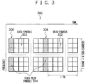
- Figure 3 shows a schematic diagram of a pilot symbol and data structure 300 in which additional pilot symbols are inserted within a Super 3G standard data chunk unit in order to assist channel estimation at user equipment.
- the additional pilot symbols are inserted at the base station 100 according to the "channel quality information" measured and reported back to the base station 100 from user equipment 200.
- the concept of adaptive pilot symbol assisted channel estimation includes two principle parts.
- data symbols 302 are arranged data chunks in which data symbols are transmitted in parallel on a number sub-carrier frequencies and at regular temporal positions during transmission of the data chunk.
- N sub-carrier frequencies are represented.
- TTI Transmission Time Interval
- Basic pilot symbols are allocated at the beginning of each data chunk.
- the basic pilot symbol - data symbol structure is fixed and the same for all channels.
- the structure consists of pilot symbols for all transmission antennae (depending on whether transmit diversity or MIMO is used).
- the pilot symbols are allocated at the beginning of a chunk of data and are spread over all sub-carrier frequencies.
- the fixed pilot symbols are referenced 304 in Figure 3 and are arranged in basic pilot symbol blocks 306 and 308 across the N sub-carrier frequencies shown in Figure 3 .
- Allocation of the basic pilot symbols as shown in Figure 3 assists in preventing the loss of channel estimation accuracy due to the effect of narrowing down the coherent bandwidth of the channel because the pilot symbols are dense and evenly distributed along the frequency domain.
- this structure is best suited as there is no variation in the time domain and channel estimates of other positions within a data chunk can be derived using linear interpolation in the time domain only.
- fixed pilot symbols 402 are allocated at the beginning of data chunks 404 and 406.
- Each of the data chunks 404 and 406 includes data symbols referenced 402 includes data symbols referenced 408 in this figure.
- adaptive pilot symbols 410 selectively replace data symbols in each data chunk 404 and 406 according to the speed of the user equipment. As the speed of the user equipment 100 increases, certain data symbols in the time domain are replaced by the adaptive pilot symbols 410 to provide reference information for channel estimation in order to combat the variation caused by the Doppler effect
- the pilot symbol-data structure 500 shown in Figure 5 more clearly illustrates the positioning of the basic fixed pilot symbols and the adaptive pilot symbols in the special and frequency domain within a single data chunk 502.
- the adaptive pilot symbols 504 are evenly distributed in the data chunk 502 in the time domain and also in the frequency domain.
- Basic pilot symbols 506 are allocated at the beginning of the data chunk 502.
- the first of the adaptive pilot symbols 504, referenced 510 is inserted at the central sub-carrier frequency 508 at a temporal distance N T from the basic pilot symbols 506.
- N T is the temporal distance between two consecutive columns of data symbols in the data chunk 502 in which adaptive pilot symbols are inserted.
- the cyclic prefix length may be used to for ⁇ max .
- adaptive pilot symbols 504 inserted in consecutive sub-carrier frequencies are temporally offset by the temporal distance N F .
- first index row 512 and second index row 514 referencing consecutive sub-carrier frequencies into which adaptive pilot symbols have been inserted. It can be seen that the pilot symbols inserted into first index row 512 and second index row 514 are temporally offset by the distance N F .
- the adaptive pilot symbols are inserted into the data chunk 502 in order to assist channel estimation in user equipment 200 as follows: Firstly, the base station 100 instructs the user equipment 200 to perform Channel Quality information (CQI) measurement via a Signal to Noise Ratio (SNR) calculation performed by the SNR calculation and speed detection block 232 shown in Figure 2 .
- CQI Channel Quality information
- SNR Signal to Noise Ratio
- the SNR calculation is based on the fixed pilot pattern structure comprising the fixed pilot pattern symbols 506 shown in Figure 5 . Regardless of the measured speed of the user equipment 200, these fixed pilot symbols 506 are always allocated at the beginning of each data chunk 502.
- the user equipment 200 performs a Doppler spread estimation calculation in the SNR calculation and speed detection block 232.
- the two measurements of SNR and Doppler spread are then mapped by the CQI mapping block 234 to a predetermined Channel Quality Indicator (CQI) index which is self decodable by the base station 100.
- CQI index is sent on an uplink channel that is scheduled for the user equipment 200.
- the base station 100 upon reception of the CQI index value from the user equipment 200, the base station 100 decodes the CQI index value and then, in the adaptive modulation and coding control and adaptive pilot insertion control block 114, determines if adaptive pilot symbol insertion is required (namely, whether the value of N T is greater than the Transmission Time Interval (TTI). If adaptive pilot symbol insertion is required, then the base station 100 performs a calculation to determine how many adaptive pilot symbols are required to be inserted.
- TTI Transmission Time Interval
- the number of adaptive pilot symbols for each chunk unit can be calculated using the below formula. This expression shall provide total number of adaptive pilot symbols to be inserted into a chunk according to the fashion described above.
- N ADAPTIVE _ PILOT _ SYM ⁇ 1 2 ⁇ ⁇ N subcarrier per chunk N F ⁇ ⁇ ⁇ N symbols per TTI per subcarrier N T ⁇ ⁇
- N T is greater than Number of symbols per TTI on one sub-carrier
- the adaptive pilot insertion is not needed as the pilot common symbols associated the data chunk is enough for channel estimation (i.e channel fading does not vary within TTI in time domain).
- the basic pilot from the consecutive chunk in time domain can be also be used to assist channel estimation on the current chunk of data symbol.
- the adaptive modulation and control coding and adaptive pilot insertion control block 114 instructs the OFDM - DSCH Hybrid Automatic Repeat Request (H-ARQ) block 104 to perform extra puncturing, or alternatively a reduction in the repetition of data symbols, in the data chunk 502 in order to leave room for the insertion of additional adaptive pilot symbols 506.
- H-ARQ Hybrid Automatic Repeat Request
- the Sub-Physical Channels (PhCH) adaptive pilot insertion and interleaving block 110 the adaptive pilot symbols 506 are inserted at the desired positions in the data chunk 502 as described previously. It should be noted that puncturing and then dummy bit insertion can also be performed in the block 104 so that simply overwriting of the data symbols at the desired positions by adaptive pilot symbols can occur in the Sub-PhCH adaptive pilot insertion and interleaving bock 110.
- PhCH Physical Channels
- the base station 100 Along with processing of the data packet for transmission to user equipment 200, the base station 100 also processes fast signalling information which includes information on the location of adaptive pilot symbols within the data chunk 502 so that the user equipment 200 can allocate and utilise the adaptive pilot symbols for channel estimation.
- the information for the user equipment 200 to identify the position of the adaptive pilot symbol pattern within a data chunk 502 is encoded to reduce the number of information bits required to be transmitted over the air interface between the base station 100 and user equipment 200.
- the fast signalling is transmitted on the Shared Control Channel (SCCH) prior to the transmission of the pilot symbols and data chunks to enable detection of the adaptive pilot symbols by the user equipment.
- SCCH Shared Control Channel
- the user equipment 200 monitors for control information intended for it, and upon the detection of such control information, performs the fast channel signal decoding in the fast signal decoder block 226 to retrieve information for performing reception and decoding of the associated shared data channel including information identifying the location of the adaptive pilot symbols in the data chunk 502.
- the information relating to the insertion of the adaptive pilot symbols is then used by the controller 230 to control the pilot and data separation carried out by the pilot and data separation block 218.
- the adaptive pilot symbols are accordingly extracted for use in enhancing the channel estimation carried out by the channel estimation block 222 to improve the data channel equalisation performed by the equalisation and transmit diversity decoding block 220.
Landscapes
- Engineering & Computer Science (AREA)
- Signal Processing (AREA)
- Computer Networks & Wireless Communication (AREA)
- Power Engineering (AREA)
- Quality & Reliability (AREA)
- Mobile Radio Communication Systems (AREA)
Claims (16)
- Procédé de génération d'un symbole pilote dans un système de communication à étalement de spectre, dans lequel des données sont transmises entre une station de base et un équipement utilisateur dans le système de communication à étalement de spectre dans des blocs de données dans lesquels des symboles de données sont transmis en parallèle sur une pluralité de fréquences de sous-porteuses et au niveau de positions temporelles régulières durant un intervalle de temps de transmission, le procédé comprenant les étapes suivantes
l'allocation de symboles pilotes de base au début de chaque bloc de données et étalés sur la pluralité de fréquences de sous-porteuse (506) ; et
le remplacement sélectif de symboles de données dans chaque bloc de données par des symboles pilotes adaptatifs en fonction de la vitesse de l'équipement utilisateur (504) ;
caractérisé en ce que l'étape de remplacement sélectif de symboles de données par des symboles pilotes adaptatifs comprend :au niveau d'une fréquence de sous-porteuse centrale du bloc de données, l'insertion des symboles pilotes adaptatifs suivant le domaine temporel, séparés par une distance temporelle 2 x NT où : où └ ┘ est un arrondi vers le bas à l'entier le plus procheoù fD est la fréquence Doppler mesurée au niveau de l'équipement utilisateur en Hz ; etoù Tsym est la durée de symbole de données en secondes.
 - Procédé selon la revendication 1, dans lequel les symboles pilotes adaptatifs sont distribués uniformément dans le bloc de données dans le domaine temporel.
- Procédé selon la revendication 1 ou 2, dans lequel les symboles pilotes adaptatifs sont distribués uniformément dans le bloc de données dans le domaine fréquentiel.
- Procédé selon la revendication 1, dans lequel le premier symbole pilote adaptatif est inséré au niveau d'une fréquence de sous-porteuse centrale à une distance temporelle de NT par rapport aux symboles pilotes de base.
- Procédé selon l'une ou l'autre des revendications 1 ou 4, dans lequel l'étape de remplacement sélectif de symboles de données par des symboles pilotes adaptatifs comprend en outre le remplacement par un espacement de fréquence NF, où
 où └ ┘ est un arrondi vers le bas à l'entier le plus procheoù Δf est la largeur de bande de sous-porteuse en Hz, etoù τ max est la dispersion maximale de retard en secondes.
 - Procédé selon la revendication 5, dans lequel la longueur de préfixe cyclique est pour Tsym.
- Procédé selon l'une ou l'autre des revendications 5 ou 6, dans lequel des symboles pilotes adaptatifs insérés dans des fréquences de sous-porteuse consécutives sont décalés temporellement de la distance temporelle de NF.
- Procédé selon l'une quelconque des revendications précédentes, et comprenant en outre l'étape suivante :l'exécution d'une perforation de symboles de données ou d'une réduction de répétition de symboles de données avant l'insertion des symboles pilotes adaptatifs.
- Procédé selon l'une quelconque des revendications précédentes, et comprenant en outre l'étape suivante :la génération d'informations de symbole pilote identifiant l'emplacement des symboles pilotes adaptatifs dans le bloc de données pour permettre à l'équipement utilisateur d'utiliser les symboles pilotes adaptatifs pour une estimation de canal.
- Procédé selon la revendication 9, dans lequel les informations de symbole pilote sont codées pour réduire le nombre de bits transmis à l'équipement utilisateur.
- Procédé selon la revendication 10, dans lequel les informations de symbole pilote sont automatiquement décodables par l'équipement utilisateur.
- Procédé selon l'une quelconque des revendications 9 à 11, dans lequel les informations de symbole pilote sont transmises avant la transmission des symboles pilotes et des blocs de données pour permettre une détection des symboles pilotes adaptatifs par l'équipement utilisateur.
- Procédé selon l'une quelconque des revendications précédentes, dans lequel le nombre NADAPTATIVE_PILOT_SYM de pilotes adaptatifs à insérer dans un bloc de données est déterminé à partir de l'expression

- Procédé selon la revendication 13, dans lequel, si NT est supérieur à un nombre de symboles, par TTI sur une porteuse unique, alors des symboles pilotes adaptatifs n'ont pas besoin d'être insérés.
- Procédé selon l'une quelconque des revendications précédentes, dans lequel les blocs de données sont transmis de la station de base à l'équipement utilisateur en utilisant un multiplexage par répartition en fréquence orthogonale.
- Procédé selon l'une quelconque des revendications précédentes, dans lequel le système de communication à étalement de spectre est conforme à des normes de systèmes LTE/Super 3G développées par le projet de partenariat de 3ème génération, 3GPP.
Priority Applications (2)
| Application Number | Priority Date | Filing Date | Title |
|---|---|---|---|
| EP12193779A EP2566089A3 (fr) | 2005-08-26 | 2006-08-25 | Structure pilote adaptative visant à assister une estimation de voie dans des systèmes à etalement du spectre |
| EP12193780.9A EP2566090B1 (fr) | 2005-08-26 | 2006-08-25 | Structure pilote adaptative d'aider d'estimation de canal dans des systèmes à étalement de spectre |
Applications Claiming Priority (3)
| Application Number | Priority Date | Filing Date | Title |
|---|---|---|---|
| AU2005904681A AU2005904681A0 (en) | 2005-08-26 | Adaptive pilot structure to assist channel estimation in spread spectrum systems | |
| AU2006203697A AU2006203697A1 (en) | 2005-08-26 | 2006-08-25 | Adaptive pilot structure to assist channel estimation in spread spectrum systems |
| PCT/JP2006/317290 WO2007024027A1 (fr) | 2005-08-26 | 2006-08-25 | Structure pilote adaptative visant a assister une estimation de voie dans des systemes a etalement du spectre |
Related Child Applications (3)
| Application Number | Title | Priority Date | Filing Date |
|---|---|---|---|
| EP12193780.9A Division-Into EP2566090B1 (fr) | 2005-08-26 | 2006-08-25 | Structure pilote adaptative d'aider d'estimation de canal dans des systèmes à étalement de spectre |
| EP12193780.9A Division EP2566090B1 (fr) | 2005-08-26 | 2006-08-25 | Structure pilote adaptative d'aider d'estimation de canal dans des systèmes à étalement de spectre |
| EP12193779A Division-Into EP2566089A3 (fr) | 2005-08-26 | 2006-08-25 | Structure pilote adaptative visant à assister une estimation de voie dans des systèmes à etalement du spectre |
Publications (3)
| Publication Number | Publication Date |
|---|---|
| EP1917748A1 EP1917748A1 (fr) | 2008-05-07 |
| EP1917748A4 EP1917748A4 (fr) | 2013-04-10 |
| EP1917748B1 true EP1917748B1 (fr) | 2018-02-28 |
Family
ID=37771751
Family Applications (3)
| Application Number | Title | Priority Date | Filing Date |
|---|---|---|---|
| EP06783151.1A Expired - Fee Related EP1917748B1 (fr) | 2005-08-26 | 2006-08-25 | Structure pilote adaptative visant à assister une estimation de voie dans des systèmes á étalement du spectre |
| EP12193779A Withdrawn EP2566089A3 (fr) | 2005-08-26 | 2006-08-25 | Structure pilote adaptative visant à assister une estimation de voie dans des systèmes à etalement du spectre |
| EP12193780.9A Expired - Fee Related EP2566090B1 (fr) | 2005-08-26 | 2006-08-25 | Structure pilote adaptative d'aider d'estimation de canal dans des systèmes à étalement de spectre |
Family Applications After (2)
| Application Number | Title | Priority Date | Filing Date |
|---|---|---|---|
| EP12193779A Withdrawn EP2566089A3 (fr) | 2005-08-26 | 2006-08-25 | Structure pilote adaptative visant à assister une estimation de voie dans des systèmes à etalement du spectre |
| EP12193780.9A Expired - Fee Related EP2566090B1 (fr) | 2005-08-26 | 2006-08-25 | Structure pilote adaptative d'aider d'estimation de canal dans des systèmes à étalement de spectre |
Country Status (6)
| Country | Link |
|---|---|
| US (4) | US8094737B2 (fr) |
| EP (3) | EP1917748B1 (fr) |
| JP (3) | JP5099004B2 (fr) |
| CN (3) | CN103078724A (fr) |
| AU (1) | AU2006203697A1 (fr) |
| WO (1) | WO2007024027A1 (fr) |
Families Citing this family (28)
| Publication number | Priority date | Publication date | Assignee | Title |
|---|---|---|---|---|
| EA014591B1 (ru) * | 2005-09-01 | 2010-12-30 | Шарп Кабусики Кайся | Способ управления передачей сигналов в системе беспроводной связи |
| EA012497B1 (ru) | 2005-10-31 | 2009-10-30 | Шарп Кабусики Кайся | Терминал связи, базовая станция и система связи |
| EP1944893B1 (fr) | 2005-10-31 | 2020-01-01 | Sharp Kabushiki Kaisha | Emetteur radio, systeme de radiocommunications, et procede d'emission radio |
| JP4611881B2 (ja) * | 2005-12-08 | 2011-01-12 | シャープ株式会社 | 適応変調制御装置、送信機、受信機、及び、適応変調制御方法 |
| US20080057972A1 (en) * | 2006-09-05 | 2008-03-06 | Nokia Siemens Network Gmbh & Co., Kg | Method for allocating resources in a radio communication system |
| MX2009004543A (es) | 2006-10-31 | 2009-05-28 | Ericsson Telefon Ab L M | Harq en sistema mimo de multiplexion espacial. |
| CN101193094B (zh) * | 2006-11-20 | 2011-10-19 | 电信科学技术研究院 | 一种发送广播/组播业务的方法及系统 |
| CN101809929B (zh) * | 2007-01-04 | 2016-11-23 | 诺基亚技术有限公司 | 对控制信道的时间频率资源的分配 |
| US8036190B2 (en) * | 2007-02-27 | 2011-10-11 | Industrial Technology Research Institute | Methods and devices for allocating data in a wireless communication system |
| KR101307123B1 (ko) * | 2007-05-04 | 2013-09-10 | 삼성전자주식회사 | 직교 주파수 분할 다중 접속 시스템에서의 데이터 송수신방법 및 장치 |
| CN101796788B (zh) * | 2007-08-31 | 2016-11-16 | 松下电器产业株式会社 | 通信装置和通信方法 |
| CN101394382B (zh) * | 2007-09-19 | 2013-01-16 | 中兴通讯股份有限公司 | 基于宽带单载波系统减少导频序列碰撞的方法 |
| US9100256B2 (en) * | 2009-01-15 | 2015-08-04 | Arndt Mueller | Systems and methods for determining the number of channel estimation symbols based on the channel coherence bandwidth |
| US8532161B2 (en) | 2009-06-22 | 2013-09-10 | Qualcomm Incorporated | Method and apparatus that facilitates estimating Doppler spread for uplink transmissions |
| US9444589B2 (en) * | 2009-10-05 | 2016-09-13 | Qualcomm Incorporated | Method and apparatus for puncturing data regions for signals to minimize data loss |
| CN102792653A (zh) * | 2009-12-08 | 2012-11-21 | 开普敦大学 | 用于提高动态频谱访问多载波系统中的信道估计性能的方法 |
| WO2011077905A1 (fr) | 2009-12-24 | 2011-06-30 | 日本電気株式会社 | Dispositif, système et procédé de communication sans fil |
| US8576936B2 (en) * | 2010-01-25 | 2013-11-05 | Harris Corporation | Method and apparatus for high speed data transmission modulation and demodulation |
| US8824527B2 (en) * | 2011-11-15 | 2014-09-02 | Acorn Technologies, Inc. | OFDM receiver with time domain channel estimation |
| CN103220237B (zh) * | 2012-01-20 | 2017-03-29 | 电信科学技术研究院 | 一种传输、接收cdma扩频符的方法及装置 |
| US20130286961A1 (en) * | 2012-04-10 | 2013-10-31 | Qualcomm Incorporated | Systems and methods for wireless communication of long data units |
| US8712331B2 (en) * | 2012-04-13 | 2014-04-29 | Motorola Solutions, Inc. | Methods and apparatus for mitigating interference between co-located collaborating radios |
| US9621389B2 (en) * | 2013-09-30 | 2017-04-11 | Volvo Car Corporation | Method to introduce complementing training symbols into a 802.11p OFDM frame in vehicular communications |
| CN104904173B (zh) * | 2013-12-26 | 2018-10-09 | 华为技术有限公司 | 信号的调制及数字信息的恢复方法、通信设备及系统 |
| US10868650B2 (en) * | 2015-05-27 | 2020-12-15 | Qualcomm Incorporated | Pilot reconfiguration and retransmission in wireless networks |
| US11223402B1 (en) | 2020-08-07 | 2022-01-11 | Facebook, Inc. | Assisted channel approximation for wireless communication of a supercell base station |
| EP4356571A1 (fr) * | 2021-06-15 | 2024-04-24 | Nokia Technologies Oy | Détermination d'erreur de prédiction de canal et transmission associée de signaux de référence |
| CN114337968B (zh) * | 2021-12-28 | 2023-06-06 | 湖南智领通信科技有限公司 | 基于实时测控数据的主动式导频调整方法及装置 |
Family Cites Families (16)
| Publication number | Priority date | Publication date | Assignee | Title |
|---|---|---|---|---|
| JP2000151548A (ja) | 1998-11-05 | 2000-05-30 | Matsushita Electric Ind Co Ltd | Ofdm通信装置 |
| US6654429B1 (en) * | 1998-12-31 | 2003-11-25 | At&T Corp. | Pilot-aided channel estimation for OFDM in wireless systems |
| JP4284774B2 (ja) * | 1999-09-07 | 2009-06-24 | ソニー株式会社 | 送信装置、受信装置、通信システム、送信方法及び通信方法 |
| EP1249955B1 (fr) * | 2000-11-17 | 2011-01-26 | Panasonic Corporation | Dispositif de communication par multiplexage frequentiel optique (ofdm) |
| EP1215833B1 (fr) * | 2000-12-14 | 2007-04-25 | Lucent Technologies Inc. | Procédé de contrôle de la qualité de service d'un système AMRC |
| US6441786B1 (en) * | 2001-07-20 | 2002-08-27 | Motorola, Inc. | Adaptive antenna array and method for control thereof |
| JP2003158499A (ja) * | 2001-11-20 | 2003-05-30 | Mitsubishi Electric Corp | 通信方法および通信装置 |
| KR100790114B1 (ko) * | 2002-03-16 | 2007-12-31 | 삼성전자주식회사 | 직교주파수 분할다중 접속 시스템에서 적응적 파일럿반송파 할당 방법 및 장치 |
| KR100507519B1 (ko) * | 2002-12-13 | 2005-08-17 | 한국전자통신연구원 | Ofdma 기반 셀룰러 시스템의 하향링크를 위한 신호구성 방법 및 장치 |
| KR100474315B1 (ko) * | 2002-12-17 | 2005-03-10 | 엘지전자 주식회사 | 기지국 수신모뎀 다중경로 탐색기의 신호 검출장치 및 그운용방법 |
| US6904550B2 (en) * | 2002-12-30 | 2005-06-07 | Motorola, Inc. | Velocity enhancement for OFDM systems |
| JP4546177B2 (ja) * | 2003-07-28 | 2010-09-15 | パナソニック株式会社 | 無線通信装置および無線通信方法 |
| KR101225172B1 (ko) * | 2003-08-20 | 2013-01-22 | 파나소닉 주식회사 | 무선 통신 장치 및 서브 캐리어의 할당 방법 |
| JP4358158B2 (ja) * | 2005-03-31 | 2009-11-04 | 株式会社エヌ・ティ・ティ・ドコモ | 送信装置および割当方法 |
| US7474611B2 (en) * | 2005-04-21 | 2009-01-06 | Telefonaktiebolaget L M Ericsson (Publ) | Reduced complexity channel estimation in OFDM systems |
| EP3457615B1 (fr) * | 2005-08-23 | 2021-09-22 | Apple Inc. | Procédés et systèmes de partitionnement de zones ofdm multiples |
-
2006
- 2006-08-25 CN CN2012104956068A patent/CN103078724A/zh active Pending
- 2006-08-25 CN CN2006800312187A patent/CN101248607B/zh not_active Expired - Fee Related
- 2006-08-25 JP JP2008505675A patent/JP5099004B2/ja not_active Expired - Fee Related
- 2006-08-25 AU AU2006203697A patent/AU2006203697A1/en not_active Abandoned
- 2006-08-25 EP EP06783151.1A patent/EP1917748B1/fr not_active Expired - Fee Related
- 2006-08-25 WO PCT/JP2006/317290 patent/WO2007024027A1/fr active Application Filing
- 2006-08-25 CN CN2012104973896A patent/CN103078725A/zh active Pending
- 2006-08-25 EP EP12193779A patent/EP2566089A3/fr not_active Withdrawn
- 2006-08-25 US US12/064,727 patent/US8094737B2/en active Active
- 2006-08-25 EP EP12193780.9A patent/EP2566090B1/fr not_active Expired - Fee Related
-
2012
- 2012-01-09 US US13/346,431 patent/US20120106596A1/en not_active Abandoned
- 2012-05-02 JP JP2012105301A patent/JP5333628B2/ja not_active Expired - Fee Related
- 2012-07-30 JP JP2012168454A patent/JP2013009382A/ja active Pending
- 2012-10-02 US US13/633,564 patent/US8588271B2/en active Active
- 2012-10-02 US US13/633,603 patent/US8576935B2/en active Active
Non-Patent Citations (1)
| Title |
|---|
| None * |
Also Published As
| Publication number | Publication date |
|---|---|
| CN103078725A (zh) | 2013-05-01 |
| EP1917748A4 (fr) | 2013-04-10 |
| US20090279589A1 (en) | 2009-11-12 |
| JP2013009382A (ja) | 2013-01-10 |
| CN103078724A (zh) | 2013-05-01 |
| JP5099004B2 (ja) | 2012-12-12 |
| US8588271B2 (en) | 2013-11-19 |
| US20130070678A1 (en) | 2013-03-21 |
| WO2007024027A1 (fr) | 2007-03-01 |
| CN101248607B (zh) | 2013-08-28 |
| EP2566089A3 (fr) | 2013-04-03 |
| EP2566090B1 (fr) | 2015-10-14 |
| EP2566090A3 (fr) | 2013-04-03 |
| US20120106596A1 (en) | 2012-05-03 |
| US8576935B2 (en) | 2013-11-05 |
| EP1917748A1 (fr) | 2008-05-07 |
| JP2012199935A (ja) | 2012-10-18 |
| US20130028294A1 (en) | 2013-01-31 |
| JP2009506583A (ja) | 2009-02-12 |
| EP2566089A2 (fr) | 2013-03-06 |
| CN101248607A (zh) | 2008-08-20 |
| JP5333628B2 (ja) | 2013-11-06 |
| EP2566090A2 (fr) | 2013-03-06 |
| US8094737B2 (en) | 2012-01-10 |
| AU2006203697A1 (en) | 2007-03-15 |
Similar Documents
| Publication | Publication Date | Title |
|---|---|---|
| EP1917748B1 (fr) | Structure pilote adaptative visant à assister une estimation de voie dans des systèmes á étalement du spectre | |
| US8902861B2 (en) | Method and apparatus for sending signaling for data transmission in a wireless communication system | |
| JP4319665B2 (ja) | 周波数分割多重接続基盤の無線通信システムにおけるデータ及び制御情報の多重化方法及び装置 | |
| AU2004247167B2 (en) | Apparatus and method for transmitting and receiving a pilot pattern for identification of a base station in an OFDM communication system | |
| US7586836B2 (en) | Apparatus and method for transmitting/receiving pilot signals in a communication system using an orthogonal frequency division multiplexing scheme | |
| KR101657554B1 (ko) | 업링크 구조를 제공하고 무선 통신 네트워크에서 파일럿 신호 오버헤드를 최소화하는 방법 및 시스템 | |
| KR100434473B1 (ko) | 직교주파수 분할 다중 시스템에서 채널 복호 장치 및 방법 | |
| KR100881967B1 (ko) | 단반송파 주파수 분할 다중접속 시스템에서 역방향 정보들의 송수신 방법 및 장치 | |
| US20040257981A1 (en) | Apparatus and method for transmitting and receiving pilot patterns for identifying base stations in an OFDM communication system | |
| TWI382698B (zh) | 於無線通訊系統中用於資料傳輸傳送訊號之方法及裝置 |
Legal Events
| Date | Code | Title | Description |
|---|---|---|---|
| PUAI | Public reference made under article 153(3) epc to a published international application that has entered the european phase |
Free format text: ORIGINAL CODE: 0009012 |
|
| 17P | Request for examination filed |
Effective date: 20080205 |
|
| AK | Designated contracting states |
Kind code of ref document: A1 Designated state(s): DE FR GB IT |
|
| RBV | Designated contracting states (corrected) |
Designated state(s): DE FR GB IT |
|
| DAX | Request for extension of the european patent (deleted) | ||
| RIC1 | Information provided on ipc code assigned before grant |
Ipc: H04L 5/00 20060101AFI20130228BHEP |
|
| A4 | Supplementary search report drawn up and despatched |
Effective date: 20130308 |
|
| RIC1 | Information provided on ipc code assigned before grant |
Ipc: H04L 5/00 20060101AFI20130301BHEP |
|
| 17Q | First examination report despatched |
Effective date: 20130418 |
|
| REG | Reference to a national code |
Ref country code: DE Ref legal event code: R079 Ref document number: 602006054821 Country of ref document: DE Free format text: PREVIOUS MAIN CLASS: H04J0011000000 Ipc: H04L0025020000 |
|
| GRAP | Despatch of communication of intention to grant a patent |
Free format text: ORIGINAL CODE: EPIDOSNIGR1 |
|
| RIC1 | Information provided on ipc code assigned before grant |
Ipc: H04L 5/00 20060101ALI20170807BHEP Ipc: H04L 25/02 20060101AFI20170807BHEP |
|
| INTG | Intention to grant announced |
Effective date: 20170911 |
|
| GRAS | Grant fee paid |
Free format text: ORIGINAL CODE: EPIDOSNIGR3 |
|
| GRAA | (expected) grant |
Free format text: ORIGINAL CODE: 0009210 |
|
| AK | Designated contracting states |
Kind code of ref document: B1 Designated state(s): DE FR GB IT |
|
| REG | Reference to a national code |
Ref country code: GB Ref legal event code: FG4D |
|
| REG | Reference to a national code |
Ref country code: DE Ref legal event code: R096 Ref document number: 602006054821 Country of ref document: DE |
|
| PG25 | Lapsed in a contracting state [announced via postgrant information from national office to epo] |
Ref country code: IT Free format text: LAPSE BECAUSE OF FAILURE TO SUBMIT A TRANSLATION OF THE DESCRIPTION OR TO PAY THE FEE WITHIN THE PRESCRIBED TIME-LIMIT Effective date: 20180228 |
|
| REG | Reference to a national code |
Ref country code: DE Ref legal event code: R097 Ref document number: 602006054821 Country of ref document: DE |
|
| PLBE | No opposition filed within time limit |
Free format text: ORIGINAL CODE: 0009261 |
|
| STAA | Information on the status of an ep patent application or granted ep patent |
Free format text: STATUS: NO OPPOSITION FILED WITHIN TIME LIMIT |
|
| 26N | No opposition filed |
Effective date: 20181129 |
|
| PG25 | Lapsed in a contracting state [announced via postgrant information from national office to epo] |
Ref country code: FR Free format text: LAPSE BECAUSE OF NON-PAYMENT OF DUE FEES Effective date: 20180831 |
|
| PGFP | Annual fee paid to national office [announced via postgrant information from national office to epo] |
Ref country code: DE Payment date: 20190830 Year of fee payment: 14 |
|
| PGFP | Annual fee paid to national office [announced via postgrant information from national office to epo] |
Ref country code: GB Payment date: 20190829 Year of fee payment: 14 |
|
| REG | Reference to a national code |
Ref country code: DE Ref legal event code: R119 Ref document number: 602006054821 Country of ref document: DE |
|
| GBPC | Gb: european patent ceased through non-payment of renewal fee |
Effective date: 20200825 |
|
| PG25 | Lapsed in a contracting state [announced via postgrant information from national office to epo] |
Ref country code: DE Free format text: LAPSE BECAUSE OF NON-PAYMENT OF DUE FEES Effective date: 20210302 |
|
| PG25 | Lapsed in a contracting state [announced via postgrant information from national office to epo] |
Ref country code: GB Free format text: LAPSE BECAUSE OF NON-PAYMENT OF DUE FEES Effective date: 20200825 |