EP1917131B1 - Apparatus and method for loading a tread press - Google Patents
Apparatus and method for loading a tread press Download PDFInfo
- Publication number
- EP1917131B1 EP1917131B1 EP06786983A EP06786983A EP1917131B1 EP 1917131 B1 EP1917131 B1 EP 1917131B1 EP 06786983 A EP06786983 A EP 06786983A EP 06786983 A EP06786983 A EP 06786983A EP 1917131 B1 EP1917131 B1 EP 1917131B1
- Authority
- EP
- European Patent Office
- Prior art keywords
- tread
- press
- loading
- support
- band
- Prior art date
- Legal status (The legal status is an assumption and is not a legal conclusion. Google has not performed a legal analysis and makes no representation as to the accuracy of the status listed.)
- Active
Links
- 238000000034 method Methods 0.000 title claims abstract description 40
- 239000000725 suspension Substances 0.000 claims description 10
- 238000000465 moulding Methods 0.000 claims description 4
- 230000033001 locomotion Effects 0.000 description 4
- 238000004519 manufacturing process Methods 0.000 description 4
- 239000000463 material Substances 0.000 description 4
- 238000012986 modification Methods 0.000 description 2
- 230000004048 modification Effects 0.000 description 2
- 238000003825 pressing Methods 0.000 description 2
- 239000002356 single layer Substances 0.000 description 2
- 238000010924 continuous production Methods 0.000 description 1
- 238000007796 conventional method Methods 0.000 description 1
- 230000001419 dependent effect Effects 0.000 description 1
- 238000000151 deposition Methods 0.000 description 1
- 239000012778 molding material Substances 0.000 description 1
- 238000005096 rolling process Methods 0.000 description 1
- 238000007493 shaping process Methods 0.000 description 1
- 239000002699 waste material Substances 0.000 description 1
Images


Classifications
-
- B—PERFORMING OPERATIONS; TRANSPORTING
- B29—WORKING OF PLASTICS; WORKING OF SUBSTANCES IN A PLASTIC STATE IN GENERAL
- B29C—SHAPING OR JOINING OF PLASTICS; SHAPING OF MATERIAL IN A PLASTIC STATE, NOT OTHERWISE PROVIDED FOR; AFTER-TREATMENT OF THE SHAPED PRODUCTS, e.g. REPAIRING
- B29C31/00—Handling, e.g. feeding of the material to be shaped, storage of plastics material before moulding; Automation, i.e. automated handling lines in plastics processing plants, e.g. using manipulators or robots
- B29C31/04—Feeding of the material to be moulded, e.g. into a mould cavity
- B29C31/08—Feeding of the material to be moulded, e.g. into a mould cavity of preforms to be moulded, e.g. tablets, fibre reinforced preforms, extruded ribbons, tubes or profiles; Manipulating means specially adapted for feeding preforms, e.g. supports conveyors
-
- B—PERFORMING OPERATIONS; TRANSPORTING
- B29—WORKING OF PLASTICS; WORKING OF SUBSTANCES IN A PLASTIC STATE IN GENERAL
- B29C—SHAPING OR JOINING OF PLASTICS; SHAPING OF MATERIAL IN A PLASTIC STATE, NOT OTHERWISE PROVIDED FOR; AFTER-TREATMENT OF THE SHAPED PRODUCTS, e.g. REPAIRING
- B29C43/00—Compression moulding, i.e. applying external pressure to flow the moulding material; Apparatus therefor
- B29C43/02—Compression moulding, i.e. applying external pressure to flow the moulding material; Apparatus therefor of articles of definite length, i.e. discrete articles
- B29C43/021—Compression moulding, i.e. applying external pressure to flow the moulding material; Apparatus therefor of articles of definite length, i.e. discrete articles characterised by the shape of the surface
-
- B—PERFORMING OPERATIONS; TRANSPORTING
- B29—WORKING OF PLASTICS; WORKING OF SUBSTANCES IN A PLASTIC STATE IN GENERAL
- B29D—PRODUCING PARTICULAR ARTICLES FROM PLASTICS OR FROM SUBSTANCES IN A PLASTIC STATE
- B29D30/00—Producing pneumatic or solid tyres or parts thereof
- B29D30/0016—Handling tyres or parts thereof, e.g. supplying, storing, conveying
-
- B—PERFORMING OPERATIONS; TRANSPORTING
- B29—WORKING OF PLASTICS; WORKING OF SUBSTANCES IN A PLASTIC STATE IN GENERAL
- B29C—SHAPING OR JOINING OF PLASTICS; SHAPING OF MATERIAL IN A PLASTIC STATE, NOT OTHERWISE PROVIDED FOR; AFTER-TREATMENT OF THE SHAPED PRODUCTS, e.g. REPAIRING
- B29C43/00—Compression moulding, i.e. applying external pressure to flow the moulding material; Apparatus therefor
- B29C43/02—Compression moulding, i.e. applying external pressure to flow the moulding material; Apparatus therefor of articles of definite length, i.e. discrete articles
- B29C43/021—Compression moulding, i.e. applying external pressure to flow the moulding material; Apparatus therefor of articles of definite length, i.e. discrete articles characterised by the shape of the surface
- B29C2043/023—Compression moulding, i.e. applying external pressure to flow the moulding material; Apparatus therefor of articles of definite length, i.e. discrete articles characterised by the shape of the surface having a plurality of grooves
-
- B—PERFORMING OPERATIONS; TRANSPORTING
- B29—WORKING OF PLASTICS; WORKING OF SUBSTANCES IN A PLASTIC STATE IN GENERAL
- B29L—INDEXING SCHEME ASSOCIATED WITH SUBCLASS B29C, RELATING TO PARTICULAR ARTICLES
- B29L2030/00—Pneumatic or solid tyres or parts thereof
- B29L2030/002—Treads
Definitions
- the present invention relates to a method for loading a tread press according to the precharacterising part of claim 1.
- the present invention further relates to an apparatus and to a device for loading tread onto a tread press according to the precharacterising part of claim 11 and of claim 16 respectively. More specifically, the present invention provides for loading a tread band onto a tread press while suspending the tread band above the mold elements as the tread band is moved into the proper longitudinal position within the tread press. Lateral positioning can also be provided using the present invention.
- Retreaded tires are commercially available and provide an economical option to obtaining additional use of a tire after the tread has worn.
- the conventional process of retreading generally includes application of a length of tire tread, referred to herein as a tread band, to a tire casing from which the original tread band or a retread band has been removed.
- the new tread band is manufactured by a process that includes providing tread features or tread sculpture to the tread band by means of a press operation.
- DE 2 032 246 A1 discloses a method, an apparatus and a device according to the precharacterising part of the independent claims and describes a press for the continuous production of tire tread strips that comprises two lines of intercommunicating and abutting open-ended molds supplied at stations with molding material, e.g. rubber.
- a movable board is controlled by combining the control of the position and speed of the movable board, the control of the pressure of the movable board and a mold clamping press mechanism so that gas in a rubber material is removed corresponding to the material and shape of the rubber material.
- JP 02167733 A discloses an apparatus with vertical rollers being adjusted so as to provide an interval slightly wider than the width of the tread.
- vertical rollers are adjusted so as to provide an interval further wider than the interval between two corresponding rollers.
- US 1,986,092 A describes a tire shaping machine and more particularly an automatic tire expanding and bagging machine that comprises means for collapsing a curing bag and releasing the collapsed bag within a tire casing and means for automatically depositing a curing bag on the collapsing means.
- a tread press is loaded by using a machine to drag the uncured tread band across the longitudinal length of the tread press until the tread is located in the proper longitudinal position. Lateral positioning of the uncured tread band in the tread press is manually provided.
- Such conventional method can lead to a waste of material and manufacturing complexities. For example, because the tread band might be stretched as it is as dragged across the press, additional thickness is sometimes added to the tread band to compensate for the stretching. Even with such compensation, such stretching may not occur uniformly along the length of the band, Improper lateral positioning may require discarding a certain section of the tread band. Manually checking and correcting the lateral position can be time and labor intensive.
- the present invention provides a method of loading a tread press.
- a tread press having a top mold element and a bottom mold element, the tread press defining a longitudinal direction.
- This method includes providing at least one tread band for molding with the tread press, seizing a first end of the tread band, moving the tread band along the longitudinal direction into a position between the top and bottom mold elements while suspending the tread band over the bottom mold element, and lowering the tread band onto the bottom mold element.
- the method may include the additional steps of pulling the tread band in the longitudinal direction while suspending it above the bottom mold element, providing at least one support under and in contact with the tread band while pulling the tread band, and moving the at least one support longitudinally along with the tread band during the step of pulling the tread band.
- the support assists in the suspension of the tread band above the bottom mold element.
- the support may allow the tread band to be freely movable with respect to the support.
- a plurality of supports may be used to assist in suspending the tread band.
- a method of loading a tread press may include moving the at least one support after the tread band has been pulled for a predetermined distance.
- a step of laterally positioning the tread band may be included, which can be also be performed during the step of lowering the tread band.
- the tread band may be pressed by moving the second mold element towards the first mold element.
- a second end of the tread band may be simultaneously moved with the second mold element during such pressing.
- the exemplary methods just referenced may include the step of laterally positioning the tread band during the step of lowering the tread band.
- the above exemplary methods may be used simultaneously for loading multiple tread bands onto a press having multiple such levels.
- the present invention provides an apparatus and method for loading a tread press that suspends the tread band above certain elements of the tread press until the tread band is property positioned longitudinally along the length of the tread press. Elements for executing a lateral positioning step may also be provided.
- a single-layer, tread band press 10 is provided as is illustrated in FIGS. 1A though 1G.
- Press 10 includes a mold element 12 and a mold back 14.
- Mold element 12 includes sculptures (represented schematically by a dashed-line) that create the tread features that are to be molded into tread band 16.
- the process for loading tread band 16 into press 10 begins by pulling tread band 16 in the longitudinal direction or in a direction along the length of press 16 as is illustrated by arrow A in FIG. 1A .
- clamp 18 grabs a first end 20 of tread band 16 and pulls along longitudinal direction A.
- tread band 16 remains suspended above mold element 12. More specifically, tread band 16 is not dragged across the surface 24 of mold element 12 but remains suspended above to prevent band 16 from being snagged or stretched.
- Tread band 16 is fed across rollers 26 on a first support 28, a second support 30, and a third support 32.
- suspended means that a tread band is supported over a mold element in a manner that reduces or minimizes the tension that would otherwise occur without suspension.
- some contact between the tread band and the mold element may still occur - i.e. the tread band may not be completely suspended at all points along its length. Nevertheless, the advantages of the present invention in reducing tension in the tread band can still be achieved in such embodiments.
- first support 28 After clamp 18 has carried first end 20 of tread band 16 a predetermined distance B ( FIG. 1 A) , first support 28 also begins to move along the longitudinal direction of the machine as indicated by arrow C in FIG. 1B . Such movement with tread band 16 provides continued support and suspension of tread band 16 above mold element 12. Preferably, clamp 18 and first support 28 move substantially at the same speed in order to maintain predetermined distance B therebetween. However, it should be understood that the present invention includes embodiments where first support 28 and clamp 18 are moved at different speeds and times relative to one another.
- first support 28 has moved a predetermined distance D ( FIG. 1 B)
- second support 30 begins to move along the longitudinal direction of the machine as indicated by arrow E to provide continued support and suspension of tread band 16.
- Second support 30 moves at substantially the same speed as first support 28 in order to maintain predetermined distance D therebetween.
- third support 32 begins to move along the longitudinal direction of the machine as indicated by arrow G.
- tread band 16 is now supported above mold element 12 in at least three positions: the first 28, second 30, and third 32 supports respectively.
- more or fewer supports may be used depending upon the weight and overall length of tread band 16.
- tread band 16 has been extended along the length of mold 10, supports 28, 30, and 32 are retracted as shown by arrows H in FIG.1E . Each support is withdrawn sequentially and preferably at the same time until each are returned to the starting position shown in FIG. 1F . As supports 28, 30, and 32 are retracted, clamp 18 remains in place and holds tread band 16 in position. Additionally, as the supports are retracted, tread band 16 may remain in tension over mold element 12. However, as shown in FIG. 1F and depending upon its weight and length, tread band 16 falls into position on mold element 12 as the first support 28 is retracted.
- first support 28 ensures that tread band 16 is properly positioned laterally by guiding tread band 16 into place as first support 28 is withdrawn to its starting position as shown in FIG. 1E .
- Such lateral positioning may be accomplished, for example, using lateral alignment rollers as will be described later herein.
- tread band press 10 is now closed by lifting mold element 12 so as to press tread band 16 against mold back 14 and thereby impress tread band 16 with the desired tread features.
- first support 28 is provided with a lift mechanism 36 by which rollers 26 on first support 28 can be lifted as shown by arrow I in FIG. 1G .
- mold back 14 and mold element 12 can be switched such that mold back 14 is below tread band 16 and mold element 12 is above.
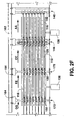
- a tread band press 110 is provided that can mold up to eight tread bands 116 simultaneously.
- Tread band press 110 is constructed with eight vertically distinct molding levels 113. Each level 113 includes a mold element 112 and a mold back 114. It is within the scope of the present invention to use a different number of levels and other mold press 110 configurations.
- Press 110 includes clamp column 140, which carries eight clamps 118 with each at a different vertical level.
- Clamps 118 are each powered and controlled by a clamp control mechanism 142. As such, clamps 118 can be activated to simultaneously grab or select tread band 116. While a clamping type mechanism is preferred, other means of grasping or selecting the first end 120 of tread band 116 may be utilized.
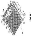
- first support column 144 carries a series of first supports 128 that are selectively positionable at vertically distinct levels.
- each first support 128 includes a series of multidirectional rollers 126 that allow tread band 116 to move across freely. Multiple rollers 126 are carried on a series of bars 146 that are placed in side-by-side fashion along the longitudinal direction MM of the machine.
- First support 128 also includes a pair of lateral alignment rollers 148. Each roller 148 can be adjusted for the width of tread band 116 using rack 150 and pinion 152. More specifically, rack 150 and pinion 152 moves with roller 148 to position roller 148 along slot 154 as shown by arrows K.
- FIG. 4B and 5A as shown tread band 116 moves across and is supported by rollers 126 on first support 128, lateral alignment rollers 148 contact the sides 117 of tread band 116 to provide proper lateral positioning.
- first support column 144 which carries the series of first supports 128, rides along rollers 156 constrained within floor track 158. Locomotion is provided by motor 160, which moves first support column 144 along rail 162 using multiple rollers 164.
- a control system (not shown) can be used in conjunction with motor 160 to position first support column 144 as desired along with the length of the press 110.
- first support column 144 includes a motor 166 and screw drive 168 ( FIG. 2A ) for powering the vertical movement of first supports 128 along first support column 144.
- the vertical position of each first support 128 can be controlled to reduce the tension of tread band 116 when tread band press 110 is closed.
- tread band press 110 also includes a second support column 170 that carries a series of second supports 130 that are positioned at vertically distinct levels.
- press 110 includes a third support column 172 that carries a series of third supports 132 that are also positioned at vertically distinct levels.
- first supports 128 second and third supports 130 and 132 each have a series of rollers 126 carried on multiple bars 146 that allow tread band 116 to move thereon freely.
- second and third support columns 170 and 172 each are powered by a motor 160 that provides for the longitudinal positioning of these columns along press 110 using multiple rollers 164.
- Second and third support columns 170 and 172 also ride on rollers 156 in floor track 158.
- second and third support columns 170 and 172 do not include motor 166 or screw drive 168. More specifically, the vertical position of the series of second and third supports 130 and 132 is fixed and is not selectively adjustable as with the series of first supports 128. It should be understood, however, that vertical adjustability may be provided if needed with either or both of second and third support columns 170 and 172.
- clamps 118 begin the process of loading press 110 by grasping first end 120 of each of the tread bands 116. Tread bands 116 are fed from a supply (now shown) through third support column 172, second support column 170, and first support column 144. Accordingly, as clamp column 140 pulls tread band 116 towards tread band press 110, tread band 116 rolls freely across the multiple rollers 126 on each of the series of first, second, and third supports, 128, 130, and 132 respectively.
- clamp column 140 pulls multiple tread bands 116 into the mold levels 113 of tread band press 110 as indicated by arrow AA. As previously described, due to a slight tension, tread bands 116 remain suspended above mold elements 112. More specifically, tread bands 116 are not dragged across mold elements 112 but remain suspended above to prevent bands 116 from being snagged or stretched.
- first support column 144 begins to move towards tread band press 110, as indicated by arrow CC, in order to maintain the suspension of tread band 116 above mold elements 112.
- clamp column 140 and first support column 144 move substantially at the same speed in order to maintain predetermined distance BB therebetween.
- second support column 170 begins to move along the longitudinal direction of the machine as indicated by arrow EE to provide continued support and suspension of tread bands 116.
- Second support column 170 moves at substantially the same speed as first support column 144 in order to maintain predetermined distance DD therebetween.
- second support column 170 acts to maintain the suspension of tread bands 116 above mold elements 112 as clamp column 140 continues to pull additional length of tread bands 116 into tread band press 110.
- third support column 172 begins to move along the longitudinal direction of the machine as indicated by arrow GG.
- third support column 172 moves at substantially the same speed as second support column 170 in order to maintain predetermined distance FF therebetween.
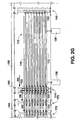
- FIG. 2F illustrates that each tread band 116 is supported above a respective mold element 112 in at least three positions by the series of first 128, second 130, and third 132 supports respectively. Using the teachings disclosed herein, one of ordinary skill in the art will appreciate that more or fewer supports may be used depending upon the weight and overall length of tread bands 116.
- tread bands 116 are extended along the length of tread band press 110, the series of first 128, second 130, and third supports 132 supports are withdrawn by the movement of the respective support columns 144, 170, and 172 as shown by arrows HH in FIG. 2G .
- Each support column is withdrawn sequentially and preferably at the same time until each are returned to the starting position shown in FIG. 2H .
- clamps 118 remain in place and hold tread bands 116 in place longitudinally. In a manner as previously described with regard to FIGS.
- tread bands 116 fall into position on mold element 12 as first support column 144 is retracted.
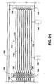
- tread band press 110 is now closed by lifting mold elements 112 using hydraulic lift mechanism 136.
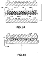
- Such lifting presses tread bands 116 against mold backs 114 and thereby impresses tread bands 116 with the desired tread features as shown in FIG. 5B .
- the series of first supports 128 on first support column 144 are lifted using motor 166 and screw drive 168 as discussed above with regard to FIG. 3 .
- mold back 114 and mold element 112 can be switched such that mold back 114 is below tread band 116 and mold element 112 is above.
- FIG. J after a proper mold time has elapsed, mold elements 112 are lowered (arrow PP) to release tread bands 116, which have been severed at second ends 122. Clamp column 140 then pulls tread bands 116 from tread band press 110 for further processing as indicated by arrow QQ. Clamp column 140 is then returned to the position illustrated in FIG. 2B where the process just described can be repeated.
Abstract
Description
- The present invention relates to a method for loading a tread press according to the precharacterising part of claim 1. The present invention further relates to an apparatus and to a device for loading tread onto a tread press according to the precharacterising part of claim 11 and of
claim 16 respectively. More specifically, the present invention provides for loading a tread band onto a tread press while suspending the tread band above the mold elements as the tread band is moved into the proper longitudinal position within the tread press. Lateral positioning can also be provided using the present invention. - Retreaded tires are commercially available and provide an economical option to obtaining additional use of a tire after the tread has worn. The conventional process of retreading generally includes application of a length of tire tread, referred to herein as a tread band, to a tire casing from which the original tread band or a retread band has been removed. Prior to such application, the new tread band is manufactured by a process that includes providing tread features or tread sculpture to the tread band by means of a press operation.
-
DE 2 032 246 A1 - A method and apparatus for molding rubber or similar products is described by
US 3,966,380 A , involving the use of a press, which is vertically arranged with hydraulic operation being provided by a hydraulic piston and cylinder apparatus, which includes means for moving a series of platens upwardly to compress therebetween certain molds. - In an apparatus for vulcanizing/pressing rubber according to
JP 2001 001358 A -
JP 02167733 A -
US 1,986,092 A describes a tire shaping machine and more particularly an automatic tire expanding and bagging machine that comprises means for collapsing a curing bag and releasing the collapsed bag within a tire casing and means for automatically depositing a curing bag on the collapsing means. - Conventionally, a tread press is loaded by using a machine to drag the uncured tread band across the longitudinal length of the tread press until the tread is located in the proper longitudinal position. Lateral positioning of the uncured tread band in the tread press is manually provided. Unfortunately, such conventional method can lead to a waste of material and manufacturing complexities. For example, because the tread band might be stretched as it is as dragged across the press, additional thickness is sometimes added to the tread band to compensate for the stretching. Even with such compensation, such stretching may not occur uniformly along the length of the band, Improper lateral positioning may require discarding a certain section of the tread band. Manually checking and correcting the lateral position can be time and labor intensive.
- Accordingly, it is the object of the invention to provide an automated apparatus and method for loading a tread press that solves these and other complexities and further automates the tread loading process. This object is achieved according to the invention by the method of claim 1, by the apparatus of claim 11 and by the device of
claim 16. Particular embodiments of the invention are the subject of the respective dependent claims. - Various features and advantages of the invention will be set forth in part in the following description, or may be obvious from the description. The present invention provides a method of loading a tread press. In the method according to the present invention, such a method is provided for a tread press having a top mold element and a bottom mold element, the tread press defining a longitudinal direction. This method includes providing at least one tread band for molding with the tread press, seizing a first end of the tread band, moving the tread band along the longitudinal direction into a position between the top and bottom mold elements while suspending the tread band over the bottom mold element, and lowering the tread band onto the bottom mold element. The method may include the additional steps of pulling the tread band in the longitudinal direction while suspending it above the bottom mold element, providing at least one support under and in contact with the tread band while pulling the tread band, and moving the at least one support longitudinally along with the tread band during the step of pulling the tread band. The support assists in the suspension of the tread band above the bottom mold element. The support may allow the tread band to be freely movable with respect to the support. A plurality of supports may be used to assist in suspending the tread band.
- Various modifications and additional steps may be included. For example, a method of loading a tread press may include moving the at least one support after the tread band has been pulled for a predetermined distance. A step of laterally positioning the tread band may be included, which can be also be performed during the step of lowering the tread band. The tread band may be pressed by moving the second mold element towards the first mold element. A second end of the tread band may be simultaneously moved with the second mold element during such pressing. Also, the exemplary methods just referenced may include the step of laterally positioning the tread band during the step of lowering the tread band. Also, the above exemplary methods may be used simultaneously for loading multiple tread bands onto a press having multiple such levels.
- These and other features, aspects and advantages of the present invention will become better understood with reference to the following description and appended claims. The accompanying drawings, which are incorporated in and constitute a part of this specification, illustrate embodiments of the invention and, together with the description, serve to explain the principles of the invention.
- A full and enabling disclosure of the present subject matter, including the best mode thereof, directed to one of ordinary skill in the art, is set forth in the specification, which makes reference to the appended figures, in which:
-
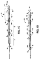
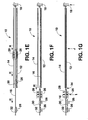
FIGS. 1A through 1G provide a schematic representation of an exemplary apparatus and method of the present invention as may be used for manufacturing a single layer of tread band. -
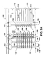
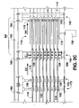
FIGS. 2A through 2J , using an elevational view of another exemplary embodiment of the present invention, illustrate another exemplary method of the present invention as may be used for manufacturing multiple tread bands simultaneously. -
FIG. 3 provides a perspective view of an element of the exemplary embodiment shown withinFIGS. 2A through 2J . -
FIGS. 4A and4B provides a perspective view that depicts the operation of other elements of the exemplary embodiment shown withinFIGS. 2A through 2J . -
FIGS. 5A and 5B provide a cross-sectional view that depicts the operation of certain elements of the exemplary embodiment shown withinFIGS. 2A through 2J andFIGS. 4A and4B . - Repeat use of identical or similar reference characters throughout the present specification and appended drawings is intended to represent same or analogous features or elements of the invention.
- Various features and advantages of the invention will be set forth in part in the following description, or may be obvious from the description. The present invention provides an apparatus and method for loading a tread press that suspends the tread band above certain elements of the tread press until the tread band is property positioned longitudinally along the length of the tread press. Elements for executing a lateral positioning step may also be provided.
- In one exemplary embodiment a single-layer,
tread band press 10 is provided as is illustrated inFIGS. 1A though 1G.Press 10 includes amold element 12 and amold back 14.Mold element 12 includes sculptures (represented schematically by a dashed-line) that create the tread features that are to be molded intotread band 16. - In one exemplary method according to the present invention, the process for loading
tread band 16 intopress 10 begins by pullingtread band 16 in the longitudinal direction or in a direction along the length ofpress 16 as is illustrated by arrow A inFIG. 1A . As shown, clamp 18 grabs afirst end 20 oftread band 16 and pulls along longitudinal direction A. Note that due to a slight tension,tread band 16 remains suspended abovemold element 12. More specifically,tread band 16 is not dragged across thesurface 24 ofmold element 12 but remains suspended above to preventband 16 from being snagged or stretched.Tread band 16 is fed acrossrollers 26 on afirst support 28, asecond support 30, and athird support 32. It should be understood that the term suspended, as used in this specification, means that a tread band is supported over a mold element in a manner that reduces or minimizes the tension that would otherwise occur without suspension. Notably, it is within the scope of the present invention that some contact between the tread band and the mold element may still occur - i.e. the tread band may not be completely suspended at all points along its length. Nevertheless, the advantages of the present invention in reducing tension in the tread band can still be achieved in such embodiments. - After
clamp 18 has carriedfirst end 20 of tread band 16 a predetermined distance B (FIG. 1 A) ,first support 28 also begins to move along the longitudinal direction of the machine as indicated by arrow C inFIG. 1B . Such movement withtread band 16 provides continued support and suspension oftread band 16 abovemold element 12. Preferably, clamp 18 andfirst support 28 move substantially at the same speed in order to maintain predetermined distance B therebetween. However, it should be understood that the present invention includes embodiments wherefirst support 28 and clamp 18 are moved at different speeds and times relative to one another. - Similarly, after
first support 28 has moved a predetermined distance D (FIG. 1 B) ,second support 30 begins to move along the longitudinal direction of the machine as indicated by arrow E to provide continued support and suspension oftread band 16.Second support 30 moves at substantially the same speed asfirst support 28 in order to maintain predetermined distance D therebetween. Oncesecond support 30 has moved a predetermined distance F (FIG. 1 C) ,third support 32 begins to move along the longitudinal direction of the machine as indicated by arrow G. As such,tread band 16 is now supported abovemold element 12 in at least three positions: the first 28, second 30, and third 32 supports respectively. Using the teachings disclosed herein, one of ordinary skill in the art will appreciate that more or fewer supports may be used depending upon the weight and overall length oftread band 16. - Once the
tread band 16 has been extended along the length ofmold 10, supports 28, 30, and 32 are retracted as shown by arrows H inFIG.1E . Each support is withdrawn sequentially and preferably at the same time until each are returned to the starting position shown inFIG. 1F . As supports 28, 30, and 32 are retracted, clamp 18 remains in place and holdstread band 16 in position. Additionally, as the supports are retracted,tread band 16 may remain in tension overmold element 12. However, as shown inFIG. 1F and depending upon its weight and length,tread band 16 falls into position onmold element 12 as thefirst support 28 is retracted. As will be discussed with another embodiment of the present invention to be later described,first support 28 ensures thattread band 16 is properly positioned laterally by guidingtread band 16 into place asfirst support 28 is withdrawn to its starting position as shown inFIG. 1E . Such lateral positioning may be accomplished, for example, using lateral alignment rollers as will be described later herein. - As depicted by arrow J in
FIG 1G ,tread band press 10 is now closed by liftingmold element 12 so as to presstread band 16 against mold back 14 and thereby impresstread band 16 with the desired tread features. In order to alleviate tension intread band 16 atfeed point 34,first support 28 is provided with a lift mechanism 36 by whichrollers 26 onfirst support 28 can be lifted as shown by arrow I inFIG. 1G . Using the teachings disclosed herein, it will be understood by one of ordinary skill in the art that mold back 14 andmold element 12 can be switched such that mold back 14 is belowtread band 16 andmold element 12 is above. These and other variations are within the scope of the present invention. Oncetread band 16 has been molded,mold element 12 is lowered andtread band 16 is removed for further manufacturing. - As will now be described, the present invention may be utilized to mold multiple tread bands simultaneously using a press having multiple levels. Referring now to
FIGS. 2A through 2J , atread band press 110 is provided that can mold up to eighttread bands 116 simultaneously.Tread band press 110 is constructed with eight verticallydistinct molding levels 113. Eachlevel 113 includes amold element 112 and a mold back 114. It is within the scope of the present invention to use a different number of levels andother mold press 110 configurations. -
Press 110 includesclamp column 140, which carries eightclamps 118 with each at a different vertical level.Clamps 118 are each powered and controlled by aclamp control mechanism 142. As such, clamps 118 can be activated to simultaneously grab orselect tread band 116. While a clamping type mechanism is preferred, other means of grasping or selecting thefirst end 120 oftread band 116 may be utilized. - As shown in
FIGS. 2A through 2J ,first support column 144 carries a series offirst supports 128 that are selectively positionable at vertically distinct levels. Referring now toFIG. 4A , eachfirst support 128 includes a series ofmultidirectional rollers 126 that allowtread band 116 to move across freely.Multiple rollers 126 are carried on a series ofbars 146 that are placed in side-by-side fashion along the longitudinal direction MM of the machine.First support 128 also includes a pair oflateral alignment rollers 148. Eachroller 148 can be adjusted for the width oftread band 116 usingrack 150 andpinion 152. More specifically,rack 150 andpinion 152 moves withroller 148 to positionroller 148 alongslot 154 as shown by arrows K. Referring toFIG. 4B and5A , as showntread band 116 moves across and is supported byrollers 126 onfirst support 128,lateral alignment rollers 148 contact thesides 117 oftread band 116 to provide proper lateral positioning. - As shown in
FIG. 3 ,first support column 144, which carries the series offirst supports 128, rides alongrollers 156 constrained withinfloor track 158. Locomotion is provided bymotor 160, which movesfirst support column 144 alongrail 162 usingmultiple rollers 164. Using the teachings disclosed herein, one of ordinary skill in the art will understand that a control system (not shown) can be used in conjunction withmotor 160 to positionfirst support column 144 as desired along with the length of thepress 110. - In a manner similar to that which was previously discussed with regard to the exemplary method and embodiment of
FIGS. 1A-1G ,first support column 144 includes amotor 166 and screw drive 168 (FIG. 2A ) for powering the vertical movement offirst supports 128 alongfirst support column 144. As such, the vertical position of eachfirst support 128 can be controlled to reduce the tension oftread band 116 whentread band press 110 is closed. - Referring again to
FIGS. 2A through 2J ,tread band press 110 also includes asecond support column 170 that carries a series ofsecond supports 130 that are positioned at vertically distinct levels. Similarly,press 110 includes athird support column 172 that carries a series ofthird supports 132 that are also positioned at vertically distinct levels. As withfirst supports 128 second andthird supports rollers 126 carried onmultiple bars 146 that allowtread band 116 to move thereon freely. As withfirst support column 144, second andthird support columns motor 160 that provides for the longitudinal positioning of these columns alongpress 110 usingmultiple rollers 164. Second andthird support columns rollers 156 infloor track 158. However, for the embodiment shown in the figures, second andthird support columns motor 166 orscrew drive 168. More specifically, the vertical position of the series of second andthird supports third support columns - An exemplary method of loading
tread band press 110 will now be further described beginning withFIG. 2B . As shown therein, clamps 118 begin the process ofloading press 110 by graspingfirst end 120 of each of thetread bands 116. Treadbands 116 are fed from a supply (now shown) throughthird support column 172,second support column 170, andfirst support column 144. Accordingly, asclamp column 140 pullstread band 116 towardstread band press 110,tread band 116 rolls freely across themultiple rollers 126 on each of the series of first, second, and third supports, 128, 130, and 132 respectively. - Referring now to
FIG. 2C ,clamp column 140 pullsmultiple tread bands 116 into themold levels 113 oftread band press 110 as indicated by arrow AA. As previously described, due to a slight tension, treadbands 116 remain suspended abovemold elements 112. More specifically, treadbands 116 are not dragged acrossmold elements 112 but remain suspended above to preventbands 116 from being snagged or stretched. Onceclamp column 140 has moved a predetermined distance BB,first support column 144 begins to move towardstread band press 110, as indicated by arrow CC, in order to maintain the suspension oftread band 116 abovemold elements 112. Preferably,clamp column 140 andfirst support column 144 move substantially at the same speed in order to maintain predetermined distance BB therebetween. - As shown in
FIG. 2D , afterfirst support column 144 has moved a predetermined distance DD,second support column 170 begins to move along the longitudinal direction of the machine as indicated by arrow EE to provide continued support and suspension oftread bands 116.Second support column 170 moves at substantially the same speed asfirst support column 144 in order to maintain predetermined distance DD therebetween. As withfirst support column 144,second support column 170 acts to maintain the suspension oftread bands 116 abovemold elements 112 asclamp column 140 continues to pull additional length oftread bands 116 intotread band press 110. - Turning now to
FIG. 2E , oncesecond support column 170 moves a predetermined distance FF,third support column 172 begins to move along the longitudinal direction of the machine as indicated by arrow GG. Preferably,third support column 172 moves at substantially the same speed assecond support column 170 in order to maintain predetermined distance FF therebetween. Astread bands 116 continue to travel intotread band press 110,FIG. 2F illustrates that eachtread band 116 is supported above arespective mold element 112 in at least three positions by the series of first 128, second 130, and third 132 supports respectively. Using the teachings disclosed herein, one of ordinary skill in the art will appreciate that more or fewer supports may be used depending upon the weight and overall length oftread bands 116. - Once
tread bands 116 are extended along the length oftread band press 110, the series of first 128, second 130, andthird supports 132 supports are withdrawn by the movement of therespective support columns FIG. 2G . Each support column is withdrawn sequentially and preferably at the same time until each are returned to the starting position shown inFIG. 2H . As supports 128, 130, and 132 are retracted, clamps 118 remain in place and holdtread bands 116 in place longitudinally. In a manner as previously described with regard toFIGS. 4A ,4B , and5A , asfirst column 144 is retractedlateral alignment rollers 148 on eachsupport 128 provide the proper lateral positioning oftread bands 116 while rolling alongsides 117. As shown inFIG. 2H and depending upon the weight and length, treadbands 116 fall into position onmold element 12 asfirst support column 144 is retracted. - As depicted by arrow NN in
FIG. 2I ,tread band press 110 is now closed by liftingmold elements 112 usinghydraulic lift mechanism 136. Such lifting presses treadbands 116 against mold backs 114 and thereby impressestread bands 116 with the desired tread features as shown inFIG. 5B . In order to alleviate tension intread bands 116 at feed point 134, the series offirst supports 128 onfirst support column 144 are lifted usingmotor 166 andscrew drive 168 as discussed above with regard toFIG. 3 . Using the teachings disclosed herein, it will be understood by one of ordinary skill in the art that mold back 114 andmold element 112 can be switched such that mold back 114 is belowtread band 116 andmold element 112 is above. These and other variations are within the scope of the present invention. - Turning now to FIG. J, after a proper mold time has elapsed,
mold elements 112 are lowered (arrow PP) to releasetread bands 116, which have been severed at second ends 122.Clamp column 140 then pulls treadbands 116 fromtread band press 110 for further processing as indicated by arrow QQ.Clamp column 140 is then returned to the position illustrated inFIG. 2B where the process just described can be repeated. - Using the teachings disclosed herein, it will be understood that variations to the apparatus and method described above fall within the scope of the claims that follow. By way of examples only, a different number of support columns may be used as necessary. A different sequence or spacing between support columns may be used to provide a proper suspension of the tread band. Again, by way of example only, the support columns and clamp column may be moved at the same time and at different speeds, at different times and equal speeds, and a variety of other combinations that provide suspension. The lateral positioning may be accomplished using different methods or apparatus, including the positioning of lateral alignment rollers on different or multiple support columns. It should be understood that the present invention includes these and other various modifications that can be made to the exemplary embodiments of apparatus and method described herein that come within the scope of the appended claims.
Claims (20)
- A method of loading a tread press (10, 110), the tread press (10, 110) having a top mold element (14, 114) and a bottom mold element (12, 112), the tread press (10, 110) defining a longitudinal direction, characterized in the steps comprising:providing at least one tread band (16, 116) for molding with the tread press (10, 110);seizing a first end (20, 120) of the tread band (16, 116);moving the tread band (16, 116) along the longitudinal direction into a position between the top and bottom mold elements (14, 114; 12, 112) while suspending the tread band (16, 116) over the bottom mold element (12, 112); andlowering the tread band (16, 116) onto the bottom mold element (12, 112).
- A method of loading a tread press (10, 110) as in claim 1, wherein said moving the tread band (16, 116) step further comprises:pulling the tread band (16, 116) in the longitudinal direction while suspending it above the bottom mold element (12, 112);providing at least one support (28, 128; 30, 130; 32, 132) under and in contact with the tread band (16, 116) during said step of pulling the tread band (16, 116), the at least one support (28, 128; 30, 130; 32, 132) assisting in the suspension of the tread band (16, 116) above the bottom mold element (12, 112); andmoving the at least one support (28, 128; 30, 130; 32, 132) longitudinally along with the tread band (16, 116) during said step of pulling the tread band (16, 116).
- A method of loading a tread press (10, 110) as in claim 2, wherein said step of moving the at least one support (28, 128; 30, 130; 32, 132) is Initiated after the tread band (16, 116) has been pulled for a predetermined distance.
- A method of loading a tread press (10, 110) In claims 2 or 3, wherein the tread band (16, 116) is freely movable with respect to said at least one support (28, 128; 30, 130; 32, 132).
- A method of loading a tread press (10, 110) as in claim 2, 3 or 4, wherein said at least one support (28, 128; 30, 130; 32, 132) comprises a plurality of supports to assist in suspending the tread band (16, 116) above the bottom mold element (12, 112).
- A method of loading a tread press (10, 110) as in any of the preceding claims, further comprising the step of laterally positioning the tread band (16, 116).
- A method of loading a tread press (10, 110) as in claim 6, where said step of laterally positioning the tread band (16, 116) occurs during said lowering the tread band (16, 116) step.
- A method of loading a tread press (10. 110) as in any of the preceding claims, further comprising the step of moving the bottom mold element (12, 112) towards the top mold element (14, 114).
- A method of loading a tread press (10, 110) as in claim 8, wherein the tread band (16, 116) has a second end (122), and further comprising the step of moving the second end (122) of the tread band (16, 116) during said step of moving the bottom mold element (12, 112) towards the top mold element (14, 114).
- A method of loading tread press (10, 110) as in any of the preceding claims, wherein said step of providing at least one tread band (16, 116) comprises providing a plurality of tread bands (16, 116).
- An apparatus for loading tread onto a tread press (10, 110), the tread press (10, 110) having a top mold element (14, 114) and a bottom mold element (12, 112), the tread press (10, 110) defining longitudinal and lateral directions, characterized in the apparatus comprising:a selecting column that is selectively positionable along the longitudinal direction relative to the top and bottom mold elements (14, 114; 12, 112);a holding device connected to said selecting column, said holding device configured for selecting the tread and holding the tread as said selecting column is moved longitudinally so as to position the tread between the top and bottom mold elements (14, 114; 12, 112); andat least one support column (144; 170; 172) that is selectively positionable along the longitudinal direction relative to the top and bottom mold elements (14, 114; 12, 112), said at least one support column (144; 170; 172) configured for supporting the tread as the tread is moved longitudinally to a position between the top and bottom mold elements (14, 114; 12, 112).
- An apparatus for loading tread onto a tread press (10, 110) as in claim 11, wherein said holding device comprises a clamp (18, 118) for grasping the end of the tread.
- An apparatus for loading tread onto a tread press (10, 110) as in claim 11, wherein said selecting column defines a vertical direction and wherein said holding device is selectively positionable along the vertical direction of said selecting column.
- An apparatus for loading tread onto a tread press (10, 110) as in claim 11, wherein said at least one support column (144; 170; 172) includes at least one support (128:130:132) comprising a plurality of rollers (126) configured for suspending the tread while simultaneously allowing the tread to move relative to said at least one support (128; 130; 132).
- An apparatus for loading tread onto a tread press (10, 110) as in claim 14, wherein said at least one support (128; 130; 132) further comprises at least one pair of lateral positioning elements configured for laterally positioning the tread along the bottom mold element (12, 112) as said at least one support column (144; 170; 172) is moved along the longitudinal direction.
- A device for loading tread onto a tread press (10, 110), the tread press (10, 110) defining longitudinal and lateral directions, characterized in the device comprising:a clamp column (140) that is selectively positionable along the longitudlnal direction of the tread press (10, 110);at least one clamp (18, 118) connected to said clamp column (140) for grasping the tread;at least one support column (144; 170; 172) that is selectively positionable along the longitudinal direction of the tread press (10, 110); andat least one support (128; 130; 132) connected to said support column (144; 170; 172), said support (128; 130; 132) configured for carrying the tread along the tread press (10, 110).
- A device for loading tread onto a tread press (10, 110) as in claim 16, where said at least one support (128; 130; 132) comprises a plurality of rollers (126) that allow the tread to slide across said at least one support (128; 130; 132).
- A device for loading tread onto a tread press (10, 110) as in claim 17, wherein said support (128; 130; 132) further comprises a lateral positioning element for locating the tread into the desired lateral position on the tread press (10, 110).
- A device for loading tread onto a tread press (10, 110) as in claim 16, said clamp column (140) defines a vertical direction relative to the tread press (10, 110), and wherein said at least one clamp (18, 118) is selectively positionable along the vertical direction of said clamp column (140).
- A device for loading tread onto a tread press (10, 110) as In claim 16, further comprising a floor track (158) along which said clamp column (140) and said at least one support column (144; 170; 172) are selectively positionable.
Applications Claiming Priority (2)
| Application Number | Priority Date | Filing Date | Title |
|---|---|---|---|
| US11/191,816 US8236228B2 (en) | 2005-07-28 | 2005-07-28 | Apparatus and method for loading a tread press |
| PCT/US2006/027007 WO2007018928A2 (en) | 2005-07-28 | 2006-07-10 | Apparatus and method for loading a tread press |
Publications (3)
| Publication Number | Publication Date |
|---|---|
| EP1917131A2 EP1917131A2 (en) | 2008-05-07 |
| EP1917131A4 EP1917131A4 (en) | 2010-03-24 |
| EP1917131B1 true EP1917131B1 (en) | 2011-06-22 |
Family
ID=37693455
Family Applications (1)
| Application Number | Title | Priority Date | Filing Date |
|---|---|---|---|
| EP06786983A Active EP1917131B1 (en) | 2005-07-28 | 2006-07-10 | Apparatus and method for loading a tread press |
Country Status (8)
| Country | Link |
|---|---|
| US (2) | US8236228B2 (en) |
| EP (1) | EP1917131B1 (en) |
| JP (1) | JP5097897B2 (en) |
| CN (2) | CN101232983B (en) |
| AT (1) | ATE513665T1 (en) |
| AU (1) | AU2006276711B2 (en) |
| CA (1) | CA2616671C (en) |
| WO (1) | WO2007018928A2 (en) |
Families Citing this family (5)
| Publication number | Priority date | Publication date | Assignee | Title |
|---|---|---|---|---|
| DE102010020060B4 (en) | 2010-05-11 | 2019-10-02 | Siempelkamp Maschinen- Und Anlagenbau Gmbh | Vulkanisierpressenanlage |
| AU2013376988A1 (en) | 2013-01-31 | 2015-08-13 | Compagnie Generale Des Etablissements Michelin | Methods and apparatus for demolding tire treads |
| US20150360395A1 (en) * | 2013-01-31 | 2015-12-17 | Michelin Recherche Et Technique S.A. | Tread cracking prevention and de-molding force reduction dolly |
| ITMI20131281A1 (en) * | 2013-07-31 | 2015-02-01 | Pirelli | METHOD AND APPARATUS FOR FEEDING A PLURALITY OF TREAD BANDS IN A PROCESS FOR PACKAGING TIRES FOR VEHICLE WHEELS |
| EP3302949B1 (en) * | 2015-05-26 | 2020-03-25 | Bridgestone Bandag, LLC | Method and apparatus for improved tread splicing |
Family Cites Families (11)
| Publication number | Priority date | Publication date | Assignee | Title |
|---|---|---|---|---|
| US1986092A (en) * | 1931-06-11 | 1935-01-01 | Morgan & Wright | Tire shaping machine |
| US3413174A (en) * | 1965-03-15 | 1968-11-26 | Goodrich Co B F | Conveyor apparatus |
| DE2032246A1 (en) | 1970-06-30 | 1972-01-13 | Vakuum VuIk Holdings Ltd , Nassau, Bahamas (Großbritannien) | Process for the continuous manufacture of treads |
| US3981669A (en) * | 1970-07-13 | 1976-09-21 | Owens-Corning Fiberglas Corporation | Molding apparatus with supporting frame for preform stock material |
| US3966380A (en) * | 1973-05-02 | 1976-06-29 | Kosik Jr Samuel J | Apparatus for loading and unloading presses |
| JPH02167733A (en) | 1988-12-22 | 1990-06-28 | Mitsubishi Heavy Ind Ltd | Apparatus for supplying material for rubber tire |
| JP3107807B2 (en) * | 1990-06-01 | 2000-11-13 | 日本石油化学株式会社 | Sheet stacking equipment |
| US5389187A (en) * | 1993-06-30 | 1995-02-14 | The Goodyear Tire & Rubber Company | Apparatus for tire tread application |
| CA2180767A1 (en) * | 1995-11-28 | 1997-05-29 | Daniel Ray Downing | Tire tread server and method |
| JP3391738B2 (en) | 1999-06-18 | 2003-03-31 | 藤倉ゴム工業株式会社 | Rubber vulcanizing press |
| CN2677135Y (en) * | 2004-03-10 | 2005-02-09 | 徐银虎 | Device for compressing linkage line on tyre surface |
-
2005
- 2005-07-28 US US11/191,816 patent/US8236228B2/en active Active
-
2006
- 2006-07-10 AU AU2006276711A patent/AU2006276711B2/en not_active Ceased
- 2006-07-10 CN CN200680027634XA patent/CN101232983B/en active Active
- 2006-07-10 EP EP06786983A patent/EP1917131B1/en active Active
- 2006-07-10 WO PCT/US2006/027007 patent/WO2007018928A2/en active Application Filing
- 2006-07-10 CN CN201110280224.9A patent/CN102490286B/en active Active
- 2006-07-10 AT AT06786983T patent/ATE513665T1/en not_active IP Right Cessation
- 2006-07-10 CA CA2616671A patent/CA2616671C/en not_active Expired - Fee Related
- 2006-07-10 JP JP2008523914A patent/JP5097897B2/en not_active Expired - Fee Related
-
2012
- 2012-03-22 US US13/427,449 patent/US8308468B2/en active Active
Also Published As
| Publication number | Publication date |
|---|---|
| JP2009502570A (en) | 2009-01-29 |
| AU2006276711B2 (en) | 2011-03-10 |
| CN102490286A (en) | 2012-06-13 |
| ATE513665T1 (en) | 2011-07-15 |
| EP1917131A2 (en) | 2008-05-07 |
| CA2616671C (en) | 2012-01-10 |
| WO2007018928A3 (en) | 2007-05-24 |
| US20120177764A1 (en) | 2012-07-12 |
| CN101232983B (en) | 2011-11-16 |
| WO2007018928A2 (en) | 2007-02-15 |
| US20070023963A1 (en) | 2007-02-01 |
| CN102490286B (en) | 2014-11-19 |
| CA2616671A1 (en) | 2007-02-15 |
| US8308468B2 (en) | 2012-11-13 |
| EP1917131A4 (en) | 2010-03-24 |
| CN101232983A (en) | 2008-07-30 |
| AU2006276711A1 (en) | 2007-02-15 |
| JP5097897B2 (en) | 2012-12-12 |
| US8236228B2 (en) | 2012-08-07 |
Similar Documents
| Publication | Publication Date | Title |
|---|---|---|
| US8308468B2 (en) | Apparatus and method for loading a tread press | |
| EP2771162B1 (en) | A molded tire tread extractor and method for manufacturing a tire tread | |
| KR102228558B1 (en) | Apparatus and method for supplying rubber sheet member | |
| US20120146262A1 (en) | Tread de-molding system | |
| US9174405B2 (en) | Tread strip curing station | |
| KR20120115216A (en) | Tire vulcanizing device | |
| JP2011062779A (en) | Holing apparatus | |
| CS277566B6 (en) | Tyre curing machine | |
| US3011211A (en) | Elastomeric strip shrinking apparatus and method | |
| CN109278330B (en) | Tread layer laminating device and tire forming machine | |
| JP2009502570A5 (en) | ||
| CN107708981B (en) | Extended ply laying process and system and apparatus therefor | |
| US5196208A (en) | Apparatus for removing cylindrical moldings from molds | |
| JPH11151763A (en) | Tire molding drum | |
| CS199646B2 (en) | Manufacturing method of curved shape rubber hoses and equipment for execution of this methos | |
| JP6262647B2 (en) | Method and plant for building tires for vehicle wheels | |
| JP2008049589A (en) | Method and apparatus for jointing strip | |
| US3732968A (en) | Apparatus for orienting material | |
| CN220316757U (en) | Blanking device of film blowing machine | |
| US2668983A (en) | Method and apparatus for removing curing bags from tires | |
| JP2023032724A (en) | Rubber member manufacturing method and apparatus | |
| JPH0811238A (en) | Tire forming machine | |
| JPS60212336A (en) | Method and apparatus for manufacturing high-lug tire | |
| JP2006205296A (en) | Elastic seamless belt reversing device and elastic seamless belt reversing method | |
| JPH01266993A (en) | Press line |
Legal Events
| Date | Code | Title | Description |
|---|---|---|---|
| PUAI | Public reference made under article 153(3) epc to a published international application that has entered the european phase |
Free format text: ORIGINAL CODE: 0009012 |
|
| 17P | Request for examination filed |
Effective date: 20080220 |
|
| AK | Designated contracting states |
Kind code of ref document: A2 Designated state(s): AT BE BG CH CY CZ DE DK EE ES FI FR GB GR HU IE IS IT LI LT LU LV MC NL PL PT RO SE SI SK TR |
|
| RIN1 | Information on inventor provided before grant (corrected) |
Inventor name: PAPIN, BERNARD Inventor name: LOUCHART, THEOPHILE HENRY Inventor name: PIKE, WILLIAM GIBBS |
|
| RIC1 | Information provided on ipc code assigned before grant |
Ipc: B29C 31/08 20060101AFI20080521BHEP |
|
| A4 | Supplementary search report drawn up and despatched |
Effective date: 20100224 |
|
| RIC1 | Information provided on ipc code assigned before grant |
Ipc: B29C 31/08 20060101AFI20080521BHEP Ipc: B29D 30/00 20060101ALI20100218BHEP |
|
| 17Q | First examination report despatched |
Effective date: 20100602 |
|
| GRAP | Despatch of communication of intention to grant a patent |
Free format text: ORIGINAL CODE: EPIDOSNIGR1 |
|
| DAX | Request for extension of the european patent (deleted) | ||
| GRAS | Grant fee paid |
Free format text: ORIGINAL CODE: EPIDOSNIGR3 |
|
| GRAA | (expected) grant |
Free format text: ORIGINAL CODE: 0009210 |
|
| AK | Designated contracting states |
Kind code of ref document: B1 Designated state(s): AT BE BG CH CY CZ DE DK EE ES FI FR GB GR HU IE IS IT LI LT LU LV MC NL PL PT RO SE SI SK TR |
|
| REG | Reference to a national code |
Ref country code: GB Ref legal event code: FG4D |
|
| REG | Reference to a national code |
Ref country code: CH Ref legal event code: EP |
|
| REG | Reference to a national code |
Ref country code: IE Ref legal event code: FG4D |
|
| REG | Reference to a national code |
Ref country code: DE Ref legal event code: R096 Ref document number: 602006022696 Country of ref document: DE Effective date: 20110811 |
|
| REG | Reference to a national code |
Ref country code: NL Ref legal event code: VDEP Effective date: 20110622 |
|
| PG25 | Lapsed in a contracting state [announced via postgrant information from national office to epo] |
Ref country code: LT Free format text: LAPSE BECAUSE OF FAILURE TO SUBMIT A TRANSLATION OF THE DESCRIPTION OR TO PAY THE FEE WITHIN THE PRESCRIBED TIME-LIMIT Effective date: 20110622 Ref country code: SE Free format text: LAPSE BECAUSE OF FAILURE TO SUBMIT A TRANSLATION OF THE DESCRIPTION OR TO PAY THE FEE WITHIN THE PRESCRIBED TIME-LIMIT Effective date: 20110622 |
|
| PG25 | Lapsed in a contracting state [announced via postgrant information from national office to epo] |
Ref country code: LV Free format text: LAPSE BECAUSE OF FAILURE TO SUBMIT A TRANSLATION OF THE DESCRIPTION OR TO PAY THE FEE WITHIN THE PRESCRIBED TIME-LIMIT Effective date: 20110622 Ref country code: AT Free format text: LAPSE BECAUSE OF FAILURE TO SUBMIT A TRANSLATION OF THE DESCRIPTION OR TO PAY THE FEE WITHIN THE PRESCRIBED TIME-LIMIT Effective date: 20110622 Ref country code: FI Free format text: LAPSE BECAUSE OF FAILURE TO SUBMIT A TRANSLATION OF THE DESCRIPTION OR TO PAY THE FEE WITHIN THE PRESCRIBED TIME-LIMIT Effective date: 20110622 Ref country code: GR Free format text: LAPSE BECAUSE OF FAILURE TO SUBMIT A TRANSLATION OF THE DESCRIPTION OR TO PAY THE FEE WITHIN THE PRESCRIBED TIME-LIMIT Effective date: 20110923 Ref country code: SI Free format text: LAPSE BECAUSE OF FAILURE TO SUBMIT A TRANSLATION OF THE DESCRIPTION OR TO PAY THE FEE WITHIN THE PRESCRIBED TIME-LIMIT Effective date: 20110622 Ref country code: CY Free format text: LAPSE BECAUSE OF FAILURE TO SUBMIT A TRANSLATION OF THE DESCRIPTION OR TO PAY THE FEE WITHIN THE PRESCRIBED TIME-LIMIT Effective date: 20110622 |
|
| PG25 | Lapsed in a contracting state [announced via postgrant information from national office to epo] |
Ref country code: NL Free format text: LAPSE BECAUSE OF FAILURE TO SUBMIT A TRANSLATION OF THE DESCRIPTION OR TO PAY THE FEE WITHIN THE PRESCRIBED TIME-LIMIT Effective date: 20110622 Ref country code: BE Free format text: LAPSE BECAUSE OF FAILURE TO SUBMIT A TRANSLATION OF THE DESCRIPTION OR TO PAY THE FEE WITHIN THE PRESCRIBED TIME-LIMIT Effective date: 20110622 |
|
| PG25 | Lapsed in a contracting state [announced via postgrant information from national office to epo] |
Ref country code: CZ Free format text: LAPSE BECAUSE OF FAILURE TO SUBMIT A TRANSLATION OF THE DESCRIPTION OR TO PAY THE FEE WITHIN THE PRESCRIBED TIME-LIMIT Effective date: 20110622 Ref country code: EE Free format text: LAPSE BECAUSE OF FAILURE TO SUBMIT A TRANSLATION OF THE DESCRIPTION OR TO PAY THE FEE WITHIN THE PRESCRIBED TIME-LIMIT Effective date: 20110622 Ref country code: IS Free format text: LAPSE BECAUSE OF FAILURE TO SUBMIT A TRANSLATION OF THE DESCRIPTION OR TO PAY THE FEE WITHIN THE PRESCRIBED TIME-LIMIT Effective date: 20111022 Ref country code: PT Free format text: LAPSE BECAUSE OF FAILURE TO SUBMIT A TRANSLATION OF THE DESCRIPTION OR TO PAY THE FEE WITHIN THE PRESCRIBED TIME-LIMIT Effective date: 20111024 |
|
| PG25 | Lapsed in a contracting state [announced via postgrant information from national office to epo] |
Ref country code: SK Free format text: LAPSE BECAUSE OF FAILURE TO SUBMIT A TRANSLATION OF THE DESCRIPTION OR TO PAY THE FEE WITHIN THE PRESCRIBED TIME-LIMIT Effective date: 20110622 Ref country code: MC Free format text: LAPSE BECAUSE OF NON-PAYMENT OF DUE FEES Effective date: 20110731 Ref country code: PL Free format text: LAPSE BECAUSE OF FAILURE TO SUBMIT A TRANSLATION OF THE DESCRIPTION OR TO PAY THE FEE WITHIN THE PRESCRIBED TIME-LIMIT Effective date: 20110622 Ref country code: RO Free format text: LAPSE BECAUSE OF FAILURE TO SUBMIT A TRANSLATION OF THE DESCRIPTION OR TO PAY THE FEE WITHIN THE PRESCRIBED TIME-LIMIT Effective date: 20110622 |
|
| REG | Reference to a national code |
Ref country code: CH Ref legal event code: PL |
|
| REG | Reference to a national code |
Ref country code: IE Ref legal event code: MM4A |
|
| PLBE | No opposition filed within time limit |
Free format text: ORIGINAL CODE: 0009261 |
|
| STAA | Information on the status of an ep patent application or granted ep patent |
Free format text: STATUS: NO OPPOSITION FILED WITHIN TIME LIMIT |
|
| PG25 | Lapsed in a contracting state [announced via postgrant information from national office to epo] |
Ref country code: CH Free format text: LAPSE BECAUSE OF NON-PAYMENT OF DUE FEES Effective date: 20110731 Ref country code: LI Free format text: LAPSE BECAUSE OF NON-PAYMENT OF DUE FEES Effective date: 20110731 |
|
| GBPC | Gb: european patent ceased through non-payment of renewal fee |
Effective date: 20110922 |
|
| 26N | No opposition filed |
Effective date: 20120323 |
|
| PG25 | Lapsed in a contracting state [announced via postgrant information from national office to epo] |
Ref country code: DK Free format text: LAPSE BECAUSE OF FAILURE TO SUBMIT A TRANSLATION OF THE DESCRIPTION OR TO PAY THE FEE WITHIN THE PRESCRIBED TIME-LIMIT Effective date: 20110622 |
|
| REG | Reference to a national code |
Ref country code: DE Ref legal event code: R097 Ref document number: 602006022696 Country of ref document: DE Effective date: 20120323 |
|
| PG25 | Lapsed in a contracting state [announced via postgrant information from national office to epo] |
Ref country code: IE Free format text: LAPSE BECAUSE OF NON-PAYMENT OF DUE FEES Effective date: 20110710 |
|
| PG25 | Lapsed in a contracting state [announced via postgrant information from national office to epo] |
Ref country code: GB Free format text: LAPSE BECAUSE OF NON-PAYMENT OF DUE FEES Effective date: 20110922 |
|
| PG25 | Lapsed in a contracting state [announced via postgrant information from national office to epo] |
Ref country code: ES Free format text: LAPSE BECAUSE OF FAILURE TO SUBMIT A TRANSLATION OF THE DESCRIPTION OR TO PAY THE FEE WITHIN THE PRESCRIBED TIME-LIMIT Effective date: 20111003 |
|
| PG25 | Lapsed in a contracting state [announced via postgrant information from national office to epo] |
Ref country code: LU Free format text: LAPSE BECAUSE OF NON-PAYMENT OF DUE FEES Effective date: 20110710 |
|
| PG25 | Lapsed in a contracting state [announced via postgrant information from national office to epo] |
Ref country code: BG Free format text: LAPSE BECAUSE OF FAILURE TO SUBMIT A TRANSLATION OF THE DESCRIPTION OR TO PAY THE FEE WITHIN THE PRESCRIBED TIME-LIMIT Effective date: 20110922 |
|
| PG25 | Lapsed in a contracting state [announced via postgrant information from national office to epo] |
Ref country code: TR Free format text: LAPSE BECAUSE OF FAILURE TO SUBMIT A TRANSLATION OF THE DESCRIPTION OR TO PAY THE FEE WITHIN THE PRESCRIBED TIME-LIMIT Effective date: 20110622 |
|
| PG25 | Lapsed in a contracting state [announced via postgrant information from national office to epo] |
Ref country code: HU Free format text: LAPSE BECAUSE OF FAILURE TO SUBMIT A TRANSLATION OF THE DESCRIPTION OR TO PAY THE FEE WITHIN THE PRESCRIBED TIME-LIMIT Effective date: 20110622 |
|
| PGFP | Annual fee paid to national office [announced via postgrant information from national office to epo] |
Ref country code: IT Payment date: 20140718 Year of fee payment: 9 |
|
| PG25 | Lapsed in a contracting state [announced via postgrant information from national office to epo] |
Ref country code: IT Free format text: LAPSE BECAUSE OF NON-PAYMENT OF DUE FEES Effective date: 20150710 |
|
| REG | Reference to a national code |
Ref country code: FR Ref legal event code: PLFP Year of fee payment: 11 |
|
| REG | Reference to a national code |
Ref country code: FR Ref legal event code: PLFP Year of fee payment: 12 |
|
| REG | Reference to a national code |
Ref country code: FR Ref legal event code: PLFP Year of fee payment: 13 |
|
| PGFP | Annual fee paid to national office [announced via postgrant information from national office to epo] |
Ref country code: FR Payment date: 20230725 Year of fee payment: 18 Ref country code: DE Payment date: 20230719 Year of fee payment: 18 |
|
| REG | Reference to a national code |
Ref country code: DE Ref legal event code: R081 Ref document number: 602006022696 Country of ref document: DE Owner name: COMPAGNIE GENERALE DES ETABLISSEMENTS MICHELIN, FR Free format text: FORMER OWNERS: SOCIETE DE TECHNOLOGIE MICHELIN, CLERMONT-FERRAND, FR; MICHELIN RECHERCHE ET TECHNIQUE S.A., GRANGES-PACCOT, CH |