EP1916640B1 - Procédé et appareil d'installation d'un système de sécurité sans fil - Google Patents
Procédé et appareil d'installation d'un système de sécurité sans fil Download PDFInfo
- Publication number
- EP1916640B1 EP1916640B1 EP07017960.1A EP07017960A EP1916640B1 EP 1916640 B1 EP1916640 B1 EP 1916640B1 EP 07017960 A EP07017960 A EP 07017960A EP 1916640 B1 EP1916640 B1 EP 1916640B1
- Authority
- EP
- European Patent Office
- Prior art keywords
- status report
- security device
- status
- input
- report
- Prior art date
- Legal status (The legal status is an assumption and is not a legal conclusion. Google has not performed a legal analysis and makes no representation as to the accuracy of the status listed.)
- Active
Links
Images


Classifications
-
- G—PHYSICS
- G08—SIGNALLING
- G08B—SIGNALLING SYSTEMS, e.g. PERSONAL CALLING SYSTEMS; ORDER TELEGRAPHS; ALARM SYSTEMS
- G08B25/00—Alarm systems in which the location of the alarm condition is signalled to a central station, e.g. fire or police telegraphic systems
- G08B25/01—Alarm systems in which the location of the alarm condition is signalled to a central station, e.g. fire or police telegraphic systems characterised by the transmission medium
- G08B25/10—Alarm systems in which the location of the alarm condition is signalled to a central station, e.g. fire or police telegraphic systems characterised by the transmission medium using wireless transmission systems
-
- G—PHYSICS
- G08—SIGNALLING
- G08B—SIGNALLING SYSTEMS, e.g. PERSONAL CALLING SYSTEMS; ORDER TELEGRAPHS; ALARM SYSTEMS
- G08B25/00—Alarm systems in which the location of the alarm condition is signalled to a central station, e.g. fire or police telegraphic systems
- G08B25/003—Address allocation methods and details
-
- G—PHYSICS
- G08—SIGNALLING
- G08B—SIGNALLING SYSTEMS, e.g. PERSONAL CALLING SYSTEMS; ORDER TELEGRAPHS; ALARM SYSTEMS
- G08B29/00—Checking or monitoring of signalling or alarm systems; Prevention or correction of operating errors, e.g. preventing unauthorised operation
- G08B29/12—Checking intermittently signalling or alarm systems
- G08B29/14—Checking intermittently signalling or alarm systems checking the detection circuits
-
- G—PHYSICS
- G08—SIGNALLING
- G08B—SIGNALLING SYSTEMS, e.g. PERSONAL CALLING SYSTEMS; ORDER TELEGRAPHS; ALARM SYSTEMS
- G08B29/00—Checking or monitoring of signalling or alarm systems; Prevention or correction of operating errors, e.g. preventing unauthorised operation
- G08B29/18—Prevention or correction of operating errors
-
- G—PHYSICS
- G08—SIGNALLING
- G08B—SIGNALLING SYSTEMS, e.g. PERSONAL CALLING SYSTEMS; ORDER TELEGRAPHS; ALARM SYSTEMS
- G08B25/00—Alarm systems in which the location of the alarm condition is signalled to a central station, e.g. fire or police telegraphic systems
- G08B25/008—Alarm setting and unsetting, i.e. arming or disarming of the security system
Definitions
- the present invention relates to surveillance systems including wireless security devices, and, more particularly, to the installation of surveillance systems including wireless security devices.
- Surveillance systems also known as security systems, are known to include wireless security devices, such as wireless motion detectors, wireless door sensors, wireless window sensors, wireless smoke detectors, etc., for monitoring a secured area of space.
- the wireless devices each transmit a unique identifier, along with any state change or supervisory data, to a receiver within the system.
- the unique identifiers are used to verify that a transmission from a wireless device actually belongs to and is being received by the intended security system, instead of, say, being transmitted from a security system in an adjacent building.
- each wireless device in use by a security system must be made known to the system by its unique identifier.
- each wireless device Before the surveillance system is operational, each wireless device must be configured. Each input and output device has a configuration that needs to be defined in order for the device to function properly.
- the configuration data includes supervision intervals, arming configuration, device type, and the unique identifier, among other things. It is a goal of the security system manufacturer to make the process of configuring a particular wireless device with its unique identifier as simple and as quick as possible for the installer.
- a traditional approach to establishing a connection within the system between a wireless device and its unique identifier has been to manually enter a series of digits of the unique identifier along with configuration data into a system controller.
- a human installer examines the panel configuration to determine where devices can be enrolled.
- the security system is placed into a special programming mode and the installer enters the unique identifier and configuration data for each device that is to be used for a particular installation.
- the installer then typically walks to each wireless device in turn and performs a physical test of each device in order to ensure that the unique identifiers and configuration data have been entered properly.
- a problem with this approach is that the process of manually entering each digit of the unique identifier information and configuration data is time-consuming and subject to installer error.
- US 2006/010078 A1 discloses systems and methods for providing registration at a remote site that may include a monitoring module for communicating with a remote site.
- a registration protocol may be used by the monitoring module and the remote site generates messages communicated during the registration process.
- WO03/001331 A describes an environmental monitoring system including a plurality of sensors and a plurality of sensor modules electrically connected to one of the sensors for generating an ID signal that uniquely identifies the sensor.
- US 2004/028023 A1 describes a system and apparatus for providing an ad hoc network of sensors. The system is based on network protocols that produce a self-organising and self-healing network. What is needed in the art is a wireless security system that can be installed without the installer having to manually enter identification information and configuration data for wireless devices.
- the present invention provides a method of installing, self-configuring and self-testing of a security system as defined by claim 1 appended hereto.
- the present invention also provides a security system as defined by claim 9 appended hereto.
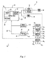
- System 10 includes a system controller 14, wireless security devices 16 1 through 16 n , and an installer interface 18.
- System controller 14 includes a control device in the form of a control panel 20 electrically connected via an option bus 22 to a wireless sensor network (WSN) hub 24, which also may be referred to as a "wLSN hub".
- Control panel 20 may include a processor 26, a memory device 28 and a telephone interface 30.
- Processor 26 may coordinate communication with the various system components including installer interface 18 and WSN hub 24.
- Memory 28 may include software for interpreting signals from wireless devices 16 and installer interface 18, and deciding based thereon whether to transmit an alarm signal from control panel 20.
- Memory 28 may also serve as a database for wireless devices 16.
- the alarm signal may be used to activate an audible alarm (not shown) within building 12, or to notify a central station receiver (CSR) (not shown) such as a security company, fire station, or police station, for example, via public telephone network 32.
- CSR central station receiver
- Memory 28 may also store identification information and configuration data for wireless devices 16, as described in more detail below.
- WSN hub 24 may include an antenna element 34 for transmitting and receiving air-borne signals, such as radio frequency signals.
- the radio frequency signals may be received by and transmitted from, i.e., exchanged with, wireless devices 16.
- Information from wireless devices 16 may be passed by WSN hub 24 to control panel 20 via option bus 22.
- Control panel 20 may pass information to WSN hub 24 via option bus 22 for transmission to wireless devices 16 as necessary.
- WSN hub 24 may include a processor 40 and memory 42 for storing software, identification information associated with wireless devices 16, and configuration data associated with wireless devices 16.
- Installer interface 18 may include an outside communication device 44, such as a cell phone, standard phone, or computer equipped with a modem; a house phone 46, which may be hard-wired to telephone interface 30 via a telephone line 48; and a manual interface 50, which may be in the form of a keypad. Manual interface 50 may be in communication with control panel 20 and WSN hub 24 via option bus 22. Thus, installer interface 18 may be in communication with system controller 14 via public telephone network 32, telephone line 48, and/or option bus 22. Installer interfaces including Ethernet or a networked connection are also possible.
- Wireless devices 16 may be in the form of any number or combination of window sensors, door sensors, glass break sensors, inertia sensors, motion detectors, smoke detectors, panic devices, gas detectors and keyfobs, for example.
- Window sensors and door sensors may detect the opening and/or closing of a corresponding window or door, respectively.
- Panic devices may be in the form of devices that human users keep on their person, and that are to be used to summon help in an emergency situation.
- Gas detectors may sense the presence of a harmful gas such as carbon monoxide, or carbon dioxide.
- a keyfob may be used to arm or disarm security system 10, and is another device that a user may possibly keep on his person.
- Each wireless device 16 includes a respective antenna element 52 for transmitting and receiving air-borne signals, such as radio frequency signals.
- the radio frequency signals may be received by and transmitted from, i.e., exchanged with, WSN hub 24.
- Wireless devices 16 1 , 16 2 and 16 3 are indicated in Figure 1 as being disposed inside building 12, and wireless device 16 n is indicated in Figure 1 as being disposed outside building 12.
- any number of wireless devices 16 may be disposed within building 12, and any number of wireless devices 16 may be disposed outside building 12.
- Types of wireless devices that may be permanently or temporarily disposed outside of building 12 during installation may include motion detectors, panic devices and keyfobs.
- wireless devices 16 may be mounted or hung in a permanent or semi-permanent desired location. Examples of such types of wireless devices 16 may include window sensors, door sensors, glass break sensors, inertia sensors, motion detectors, smoke detectors, and gas detectors. Other types of wireless devices 16 may be disposed in temporary locations during installation, or may even be in motion, such as a panic device or keyfob being carried on a user's person.
- a human installer positioned within building 12 may access installer interface 18 such as by picking up the receiver on house phone 46, or by actuating keys on manual interface 50.
- house phone 46 there may be a modern-equipped computer (not shown) within building 12 that is attached to telephone line 48 and that may be used as an installer interface.
- a human installer disposed outside of building 12 may remotely communicate with system 10 by calling a dedicated telephone number associated with security system 10. The calling of the dedicated telephone number may be performed via public telephone network 32 and an outside telecommunication device 44, which is illustrated as a standard telephone in Figure 1 , but may alternatively be in the form of a cell phone or a computer equipped with a modern.
- the dedicated telephone number associated with security system 10 may be the same number that is used by house phone 46 for voice communication. Regardless of which of outside telecommunication device 44, house phone 46, and manual interface 50 is used, the installer may follow system prompts to thereby cause system 10 to enter a wireless maintenance mode of operation.
- an installer may press a test button (not shown) on control panel 20 in order to implement an automatic self-test procedure.
- the system may be taken directly to a wireless mode in which the installer is bypassed and the security devices are learned and automatically configured.
- pressing the test button for two seconds and releasing it may cause the panel to run through a test sequence.
- the human installer running the test may be asked to press the '1' button on a keypad (not shown) for a point walk test or press '5' to skip it. If the installer presses '1', and the system has a wLSN hub connected that has not been initialized, then the panel may start the discovety/configuration/test process with no further input until the devices are ready to be activated.
- the installer may make appropriate selections via installer interface 18 in order to transmit an installation initiation signal directing WSN hub 24 to go into a discover mode. If the user is disposed outside of structure 12, he may remotely transmit the installation initiation signal via a cell phone, for example. In the discover mode, hub 24 may be instructed to "discover" wireless devices, such as wireless devices 16, that need to be installed in system 10.
- Discovering a wireless device may include receiving, assigning, or otherwise ascertaining unique identification information and configuration data for that device, such as an identification number, a type of the device, time periods when the device is on and off, supervision intervals (i.e., how often the device should report its status), operational parameters based upon the regulations in which the system is to operate, and/or a function of the device.
- unique identification information and configuration data such as an identification number, a type of the device, time periods when the device is on and off, supervision intervals (i.e., how often the device should report its status), operational parameters based upon the regulations in which the system is to operate, and/or a function of the device.
- system controller 14 issues an airborne signal requesting that each wireless device 16 that receives the request reply with an identification number and the type of the device.
- System controller 14 may store each identification number and its associated type in memory 28 for further reference.
- the identification number may be any string of alphanumeric characters and/or bits that uniquely identifies the wireless device with which the identification information is associated. This identification number may be included within any signal transmitted from a wireless device, both during installation and during surveillance operation of system 10, in order to identify which of wireless devices 16 that the signal is being transmitted from.
- the device type information may specify whether the wireless device is a window sensor, door sensor, glass break sensor, inertia sensor, motion detector, smoke detector, gas detector, panic device or keyfob, for example.
- the device type information may further break down these categories by subcategories such as indoor or outdoor motion detector, garage door or front door sensor, carbon monoxide or carbon dioxide, etc.
- each wireless device should be configured based upon the type of the wireless device. For example, if a wireless device is a smoke detector type, then it may be assumed that the wireless device should remain ON continually. It may be further assumed that the wireless device should have a supervision interval of about two hundred seconds. That is, the smoke detector should report its status at least every two hundred seconds, as required by United States regulations. As another example, if a wireless device is an interior motion detector type, then it may be assumed that the wireless device should be ON only after a user has entered a valid arming code into manual interface 50 and a door sensor detects the opening and closing of an exterior door within a certain time period thereafter. It also may be assumed that the wireless device should have a supervision interval of about four hours. That is, the interior motion detector should report its status at least every four hours. Of course, if the interior motion detector were to detect motion within that four hour period, then the detector would report its new status immediately, or as soon as the detection of motion could be confirmed.
- the function information may include the conditions under which control panel 20 should transmit an alarm signal, or take some other action, in response to the wireless device transmitting a notification signal during surveillance operation.
- the notification signal from the wireless device may indicate, in the case of a panic device or keyfob, that a button on the panic device or keyfob is being actuated, or may indicate that the wireless device is sensing motion, sound, smoke, gas, the opening of a door/window, etc. For example, if a door sensor is on a door that can be unlocked from outside building 12 with a key, then it may be desirable to transmit an alarm signal only under the condition that an arm/disarm code has not been entered on manual interface 50 within one minute after the door is opened.
- a human installer may visit each wireless security device and perform some type of actuation that serves to activate the device. For example, the installer may press a button on each device to thereby activate the device.
- the manual activation of the devices causes each device to respond by transmitting an air-borne signal including its unique identifier.
- the wireless device may also report the state that it is currently in.
- a motion sensor may report that it is detecting motion, which may be due to either the movements of the human installer or software code within the sensor that directs the sensor to report motion automatically upon activation by the installer.
- a smoke detector would likely be designed to report that it detects the presence of smoke upon human activation regardless of whether smoke is actually present at the time of activation.
- system controller 14 may look up the device's type, which may be stored in memory 28 or may be accessed on-line via the internet. Based on the device type, system controller 14 may make some assumptions about how the device should be configured, as discussed above. System controller 14 then may monitor the device dependent upon the type of the device.
- the term "monitoring” may include supervising the security devices, such as by sending instruction signals to the security devices. The term “monitoring” may also include processing reporting signals from the security devices and deciding what action should be taken in response to the reporting signals. For example, system controller 14 may cause an alarm to issue depending upon both a reported change of status of the security device, and how the device has been configured.
- Instruction signals transmitted from system controller 14 to devices 16 may generally specify the configuration of the devices. That is, the instruction signals may instruct the devices how often to report status (i.e., the supervision interval), and during what time periods to be in an active state (i.e., the duty cycle).
- hub 24 may give control panel 20 the identification and type information from all wireless devices 16 that transmit such information in response to being requested therefor. These discovered wireless devices may be respectively assigned the next available panel zone numbers in addition to the unique identifiers that may be provided by the devices themselves. System controller 14 may assign each wireless device a respective zone number for reporting purposes (e.g., device 6 is in alarm). This number may be used in communication within and between control panel 20 and hub 24, but may not be communicated to the device to which the number has been assigned.
- Zone numbers may be assigned based on groups of wireless device types. For example, all the window sensors that respond may be assigned consecutive zone numbers beginning with the first available zone number that is available. Control panel 20 may then assign zone numbers to the motion detectors, picking up where the assignment of zone numbers to the window sensors left off. Next, zone numbers may be assigned to smoke detectors, and so on until all devices that responded are assigned a zone number.
- testing may be completed upon the device transmitting a report indicating that its state has changed since its initially reported state. For example, a motion detector that initially reported the presence of motion (due to movements of the human installer or automatically by design) may time out after the installer has walked out of range. After timing out, the motion detector may report that motion is no longer present. Having received reports of each of two possible statuses (motion and no motion) from the motion detector, the system controller's testing of the motion detector is complete.
- a smoke detector that initially reported the presence of smoke may time out a predetermined time period after the installer has released an activation button. After timing out, the smoke detector may report that smoke is no longer present. Having received reports of each of two possible statuses (smoke and no smoke) from the smoke detector, the system controller's testing of the smoke detector is complete.
- system 10 may enter an operational mode in which system 10 performs its intended function of providing surveillance.
- wireless devices 16 continue to report their statuses according to and dependent upon their configurations, and system controller 14 continues to monitor devices 16 according to and dependent upon the configurations of devices 16.
- Each wireless device 16 may be provided with an LED 54 that may light up or flash to indicate to the installer that the wireless device is transmitting, or has recently transmitted, some type of signal. If the LED does not light up or flash at the desired device, then the installer may need to performs some troubleshooting. For example, the installer may check the battery (not shown) of the wireless device or replace the wireless device with another one.
- control system 14 may assign to a wireless device 16 to be changed to suit a particular application.
- a user may access manual interface 50 and key in replacement configuration data for the wireless device.
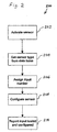
- a sensor is activated.
- a human installer may activate a smoke detector by pressing a test button on the smoke detector, thereby causing the smoke detector to transmit a code to the system controller indicating the smoke detector's unique identification number.
- the system controller uses the received code to retrieve the sensor type (smoke detector) from the sensor database in memory 28.
- an input number, or zone number is assigned by the system controller to the reporting sensor. The system controller may use this input number to identify which of the wireless devices that a particular report has been received from.
- the sensor is configured.
- system controller may inform the sensor with regard to how frequently the sensor should report its status, during what time periods the sensor should be actively sensing, and which country's operational regulations to follow.
- the configuration may be dependent upon the type of sensor.
- control panel 20 may report to hub 24 that the sensor (input) has been tested and configured. Testing may be completed upon the sensor timing out after activation and reporting the second of its two possible states. At this point, the system controller has confirmed that the sensor is capable of reporting both of its states.
- FIG. 3 illustrates another embodiment of a method 300 of the present invention for installing a security system.
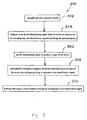
- a security device is manually activated.
- a human installer may press a button on a door sensor in order to activate the door sensor.
- an air-borne identification signal is transmitted from the device in response to the activating step.
- the identification signal identifies the actuated device. More particularly, in response to having its button pushed, the door sensor may transmit a radio frequency signal that uniquely identifies the door sensor as the wireless device that has been activated.
- the identification signal is used to ascertain a type of the device.
- the system controller may use the unique identification number in referencing a look up table in memory 28 that associates the number with the type of the device, i.e., a door sensor.
- the device is automatically wirelessly configured dependent upon the type of the device, the configuring being in response to the identification signal. For instance, the system controller may wirelessly transmit configuration data to the sensor depending upon its type.
- the device may be configured to have a relatively short supervision interval, such as 200 seconds. If, however, the device is an interior motion detector type, then the device may be configured to have a relatively lengthy supervision interval, such as four hours.
- Configuration of the device's duty cycle may also depend upon the type of the device. For example, a smoke detector may remain ON continuously, while an interior motion detector may be ON only while people have vacated the building.
- These configuration parameters may be transmitted from the system controller (specifically, the hub) to the wireless devices via air-borne signals.
- aspects of monitoring such as the transmitted configuration data and how often the system controller receives reporting signals, may be dependent upon the sensor's type.
- a zone number is automatically assigned to the device in response to the identification signal.
- a zone number may be used internally by the system controller to compartmentalize communications with a particular device. Devices of the same type may be assigned consecutive zone numbers.
- an exemplary wireless device 16 is shown in Figure 4 as having a battery 56 as a back up power source.
- Device 16 also includes a DC power supply 58 that may be plugged into a power source in the form of a conventional wall receptacle 60.
- the use of DC power supply 58 may be desirable for a device 16 in the form of an alarm siren, for example.
- battery 56 is the primary power source and no DC power supply is included.
- DC power supply 58 is an option (i.e., is not standard equipment), its presence/absence comprises a sub-input of device 16 in addition to the other sub-input comprised by whether the alarm siren is sounding an alarm or not.
- a DC power supply may also be particularly appropriate for application to a relay type wireless device that controls the application of power to another security device. It is also possible, in other embodiments, for a trickle charger to be used in place of a DC power supply. Such a trickle charger would continually recharge a rechargeable version of battery 56.
- an alarm siren type of device may initially report that it is sounding an alarm before timing out and then reporting its actual state of not sounding an alarm. Thus, the system controller has received reports in each of the two states, and that aspect of testing is complete. If power supply 58 is present and plugged in during testing, then device 16 may initially report as a sub-input that the voltage from power supply 58 is absent. After the short time-out period, device 16 may report that the voltage from power supply 58 is present, and thus that aspect of testing is also complete. However, if power supply 58 is absent during testing, then device 16 may report as a sub-input that the voltage from power supply 58 is absent, and may continue to report the absence after the time-out period.
- system controller 14 does not receive each of two possible states of the sub-input of power supply presence/absence, testing of this sub-input is not completed. If a source of a sub-input such as a power supply is not present in a wireless device, then it may not be possible for an installer to activate that sub-input during testing.
- any subsequent loss of power from power supply 58 may be reported by device 16 as a trouble condition that should be investigated, and system controller 14 may treat it as a trouble condition. For example, system controller 14 may energize a red warning light on control panel 20, and/or periodically emit an audible beep, to thereby notify the user of the trouble.
- device 16 may continue to report the absence of power from a power supply as a trouble condition that should be investigated. This may be a problem if system controller were to respond by notifying the user of trouble when in fact there is no trouble because no power supply was ever installed.
- a mask is applied to this power supply present/absent sub-input because testing of the sub-input was not completed.
- system controller 14 may ignore subsequent reports of a missing power supply and not treat it as a trouble condition.
- Device 16 in Figure 5 may be a door/window sensor that is capable of detecting whether the door/window is open or closed by employment of a magnetic contact 62 and/or a wired contact 64.
- the presence of a magnetic field or a voltage may be sensed by contacts 62, 64, respectively, in order to detect whether a window/door is open or closed. Only one of the two contacts may be required for most applications, although both contacts may be employed when security needs are particularly crucial.
- Device 16 may report the status of both magnetic contact 62 and wired contact 64, regardless of whether both contacts are actually present.
- device 16 may report that both contacts 62, 64 are open, either automatically or due to the door/window actually being open. After the door/window is closed by the installer, or after a time-out period if the door/window is already closed, device 16 may report that whichever one(s) of contacts are actually present and are actually closed are indeed closed. If either of contacts 62, 64 are not present in device 16, then device continues to report that the missing contact is open. Thus, any missing contact does not have a status reported in both states, and does not have its testing completed.
- the open state of the missing contact may be reported by device 16 as an alarm condition that should be responded to by sounding a siren alarm. Because the door/window is not actually open, sounding the alarm would be a nuisance to the user, to neighbors, and to the police who might respond to the alarm. However, according to the invention, a mask is applied to whichever one(s) of the magnetic contact and wired contact sub-inputs is not fully tested. System controller 14 may ignore subsequent reports of an open window/door from any sub-input contact to which a mask has been applied and not treat it as an alarm condition.
- Device 16 in Figure 6 may be an inertia type sensor that is capable of detecting whether the glass of a window has been broken, for example, by employment of a magnetic contact 66 and/or a motion sensing module 68. Only one of magnetic contact 66 and motion sensing module 68 may be required for most applications, although both may be employed when security needs are particularly crucial.
- the system controller's treatment of reports from these two sub-inputs in deciding whether to issue an alarm may be substantially similar to the treatment described above with reference to Figure 5 , an thus is not described in detail herein in order to avoid needless repetition.
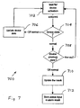
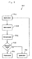
- a wireless device in the security system is activated. For example, an installer may press a button on a wireless smoke detector in order to activate the smoke detector.
- a device state is determined.
- the smoke detector may have two sub-inputs, each of which has its own state. A first sub-input may be whether the presence of smoke is detected, and a second sub-input may be whether the presence of a power supply voltage is detected.
- the smoke detector may automatically report the presence of smoke, which may be designated as "Off normal” in the flow chart of Figure 7 , and the device state is updated as such in step 706. Operation returns to step 702, and after a time-out period has passed, the smoke detector report may revert to its previous state before activation, which may be referred to as "normal” (smoke absent). This reversion back to the normal state functions, in step 702, as a second activation. At this point, both states of the smoke detector (smoke present/smoke absent) have been reported by the smoke detector and testing is complete. Thus, in step 704, the device state is "normal” and operation continues to step 708.
- step 708 If the device responded with an "Off normal" report after the initial activation, then the previous state is determined to be “Off normal” in step 708 and operation continues to step 710.
- the mask for this sub-input of smoke presence is updated, i.e., the mask for this sub-input is removed, and the smoke presence is stored in memory 28 as an active sub-input in the alarm mask (step 712).
- any subsequent reports of the presence of smoke will be treated by system controller 14 as a valid alarm condition. If, however, the device did not respond with an "Off normal" report after the initial activation, then operation proceeds from step 704 directly to step 708 without ever passing through step 706. This may be the case if the smoke detector is malfunctioning in some way.
- step 708 the previous state is determined as "normal” and operation reverts back to step 702.
- the mask is not removed from the sub-input of smoke presence, and operation may continue in an endless loop including steps 702, 704, 708 until the smoke detector properly responds with an "Off normal” report in response to being manually activated.
- the smoke detector may report the state (step 704) of absence of external voltage, which may be referred to and updated as "off formal" (step 706). Because the smoke detector has not reported the second state (power supply voltage present) for this sub-input, testing is not completed, and any subsequent reports of the lack of power supply voltage from the smoke detector may be ignored by system controller 14. Operation then returns to step 702, where another activation is awaited in the event that an external power supply has been added.
- Method 800 may be a continuation of method 700, and thus may be described herein with reference thereto.
- a report of an alarm condition is awaited.
- a report of an alarm condition is received, such as from the smoke detector referenced with respect to method 700 above. That is, the smoke alarm may report the presence of smoke.
- the alarm mask is obstained, such as from memory 28. The alarm mask may be used to determine whether the smoke detector is a valid alarm source in step 808.
- step 810 system controller 14 may cause an alarm siren to sound. If, in step 810, the alarm source has not been tested, and thus a mask is applied to the alarm source, then system controller 14 may not cause an alarm siren to sound. That is, the alarm may be ignored (step 812).
- Method 800 has been described as applying to the processing of the report of an alarm condition. However, method 800 may be equally applicable to the processing ofthe report of a trouble condition.
- a trouble condition report may be received from the smoke detector discussed above with reference to method 700, wherein the report indicates that no external voltage is present.
- a trouble condition mask may be used to determine whether the detection of a power supply is a valid trouble condition source. If, as described above with reference to method 700, the power supply detection sub-input of the smoke detector has not been fully tested, and thus a mask is applied to the trouble condition source, then system controller 14 may not cause a trouble condition to be indicated. That is, the trouble condition may be ignored in a step analogous to step 812.
- step 810 system controller 14 may cause a trouble light to be energized, and/or may cause an audible tone to be emitted periodically.
- a security device such as a smoke detector
- a first status report is transmitted from the device in response to the activating step, the first status report indicating a fault condition of an input of the security device regardless of whether the fault condition exists.
- Either an alarm condition or a trouble condition may be regarded as a fault condition.
- a status report may be transmitted from the smoke detector in response to the activation. The status report may indicate the presence of smoke, regardless of whether smoke actually is present.
- a second status report is transmitted from the device after the first status report has been transmitted, the second status report being indicative of an actual status of the input of the security device. For instance, after a suitable time-out period, the smoke detector may send another report. This second report may indicate whether smoke is in reality present.
- the first and second status reports may be transmitted in a testing mode, and a third status report, as well as numerous subsequent status reports, may be transmitted in an operational mode.
- a third status report may be transmitted from the device after the second status report has been transmitted, the third status report being indicative of the input of the security device being in an actual fault condition. That is, the smoke detector may at some later point send another status report indicating the presence of smoke.
- the first status report indicates a status different than the status indicated by the second status report.
- the smoke detector indicated an absence of smoke
- the smoke detector has been fully tested, and the third status report may be regarded as credible.
- the smoke detector continued to indicate an absence of smoke in the second status report, it may indicate that the smoke detector is not operating correctly or its smoke detecting features are missing entirely.
- the third status report in step 908 which continues to indicate the presence of a fault condition (smoke) may not be credible.
- a fault warning is issued in response to the third status report only if the second status report is indicative of an absence of a fault condition of the input of the security device. That is, unless the smoke detector has previously indicated the absence of smoke, then the indication of smoke in the third status report may not be credible, and thus may be ignored.
- method 900 has been described as applying to one input of a security device. However, it is to be understood that the methods of the present invention may be separately and independently applied to each of a plurality of inputs of a security device.
- Manual interface 50 may be used by the user to alter the masks such that sub-inputs may be added or removed dynamically. Particularly, interface 50 may be used to add a mask when a sub-input has been removed, and delete a mask when a sub-input is added.
- the present invention has been described herein in connection with wireless security devices. However, it is to be understood that many aspects of the present invention are equally applicable to conventional, hard-wired security devices.
Landscapes
- Physics & Mathematics (AREA)
- General Physics & Mathematics (AREA)
- Engineering & Computer Science (AREA)
- Computer Security & Cryptography (AREA)
- Business, Economics & Management (AREA)
- Emergency Management (AREA)
- Computer Networks & Wireless Communication (AREA)
- Alarm Systems (AREA)
Claims (12)
- Procédé d'installation, d'autoconfiguration et d'autotest d'un système de sécurité (10), ledit procédé comprenant les étapes consistant à :activer (902) un dispositif de sécurité (16) ;transmettre automatiquement (904) un premier rapport d'état à partir du dispositif de sécurité en réponse à l'étape d'activation, le premier rapport d'état indiquant un état défectueux d'une entrée du dispositif de sécurité indépendamment du point de savoir si l'état défectueux existe ;transmettre automatiquement (906) un deuxième rapport d'état à partir du dispositif de sécurité après que le premier rapport d'état a été transmis, le deuxième rapport d'état étant indicatif d'un état réel de l'entrée du dispositif de sécurité ;transmettre automatiquement (908) un troisième rapport d'état à partir du dispositif après que le deuxième rapport d'état a été transmis, le troisième rapport d'état étant indicatif du fait que l'entrée du dispositif de sécurité est dans un état défectueux réel, etémettre (910) un avertissement de défaillance en réponse au troisième rapport d'état seulement si le deuxième rapport d'état est indicatif d'une absence d'un état défectueux de l'entrée du dispositif de sécurité.
- Procédé selon la revendication 1, dans lequel l'état défectueux indiqué par le premier rapport d'état représente un état d'alarme ou un état de problème.
- Procédé selon la revendication 1, dans lequel le premier rapport d'état indique une présence de fumée, indépendamment du point de savoir si de la fumée est ou non réellement présente.
- Procédé selon l'une quelconque des revendications précédentes, dans lequel le deuxième rapport d'état est transmis après une période de temporisation.
- Procédé selon l'une quelconque des revendications précédentes, dans lequel le deuxième rapport d'état indique si de la fumée est présente en réalité.
- Procédé selon l'une quelconque des revendications précédentes, dans lequel les premier et deuxième rapports d'état sont transmis dans un mode de test et le troisième rapport d'état est transmis dans un mode opérationnel.
- Procédé selon l'une quelconque des revendications précédentes, dans lequel, afin de déterminer une crédibilité du deuxième rapport d'état, il est déterminé si le premier rapport d'état indique ou non un état différent de l'état indiqué par le deuxième rapport d'état.
- Procédé selon la revendication 7, dans lequel si le deuxième rapport d'état continue à indiquer une absence d'un état défectueux, alors le troisième rapport d'état qui continue à indiquer la présence de l'état défectueux est déterminé comme n'étant pas crédible.
- Système de sécurité (10) comprenant :au moins un dispositif de sécurité (16) configuré pour :transmettre automatiquement (904), en réponse au fait d'être activé, un premier rapport d'état, le premier rapport d'état indiquant un état défectueux d'une entrée du dispositif de sécurité indépendamment du point de savoir si l'état défectueux existe ;transmettre automatiquement (906) un deuxième rapport d'état à partir du dispositif de sécurité après que le premier rapport d'état a été transmis, le deuxième rapport d'état étant indicatif d'un état réel de l'entrée du dispositif de sécurité ;transmettre automatiquement (908) un troisième rapport d'état à partir du dispositif après que le deuxième rapport d'état a été transmis, le troisième rapport d'état étant indicatif du fait que l'entrée du dispositif de sécurité est dans un état défectueux réel, etémettre (910) un avertissement de défaillance en réponse au troisième rapport d'état seulement si le deuxième rapport d'état est indicatif d'une absence d'un état défectueux de l'entrée du dispositif de sécurité.
- Système selon la revendication 9, dans lequel ledit dispositif de sécurité (16) est configuré pour être activé par un installateur humain.
- Système selon la revendication 10, dans lequel ledit dispositif de sécurité (16) comprend au moins l'un d'un capteur de fenêtre, d'un capteur de porte, d'un capteur de bris de vitre, d'un détecteur de mouvement, d'un détecteur de fumée, d'un dispositif anti-panique, d'un détecteur de gaz et d'un porte-clés.
- Système selon la revendication 9, dans lequel ledit dispositif de sécurité (16) est configuré pour entrer dans un mode opérationnel après réception des signaux de rapport d'état transmis automatiquement.
Applications Claiming Priority (1)
| Application Number | Priority Date | Filing Date | Title |
|---|---|---|---|
| US11/585,391 US7746222B2 (en) | 2006-10-23 | 2006-10-23 | Method and apparatus for installing a wireless security system |
Publications (3)
| Publication Number | Publication Date |
|---|---|
| EP1916640A2 EP1916640A2 (fr) | 2008-04-30 |
| EP1916640A3 EP1916640A3 (fr) | 2008-11-26 |
| EP1916640B1 true EP1916640B1 (fr) | 2013-07-10 |
Family
ID=38982899
Family Applications (1)
| Application Number | Title | Priority Date | Filing Date |
|---|---|---|---|
| EP07017960.1A Active EP1916640B1 (fr) | 2006-10-23 | 2007-09-13 | Procédé et appareil d'installation d'un système de sécurité sans fil |
Country Status (2)
| Country | Link |
|---|---|
| US (1) | US7746222B2 (fr) |
| EP (1) | EP1916640B1 (fr) |
Families Citing this family (72)
| Publication number | Priority date | Publication date | Assignee | Title |
|---|---|---|---|---|
| US11343380B2 (en) | 2004-03-16 | 2022-05-24 | Icontrol Networks, Inc. | Premises system automation |
| US8635350B2 (en) | 2006-06-12 | 2014-01-21 | Icontrol Networks, Inc. | IP device discovery systems and methods |
| US11368327B2 (en) | 2008-08-11 | 2022-06-21 | Icontrol Networks, Inc. | Integrated cloud system for premises automation |
| US10721087B2 (en) | 2005-03-16 | 2020-07-21 | Icontrol Networks, Inc. | Method for networked touchscreen with integrated interfaces |
| US11582065B2 (en) | 2007-06-12 | 2023-02-14 | Icontrol Networks, Inc. | Systems and methods for device communication |
| US11811845B2 (en) | 2004-03-16 | 2023-11-07 | Icontrol Networks, Inc. | Communication protocols over internet protocol (IP) networks |
| US11190578B2 (en) | 2008-08-11 | 2021-11-30 | Icontrol Networks, Inc. | Integrated cloud system with lightweight gateway for premises automation |
| JP2007529826A (ja) | 2004-03-16 | 2007-10-25 | アイコントロール ネットワークス, インコーポレイテッド | 対象事項管理ネットワーク |
| US11677577B2 (en) | 2004-03-16 | 2023-06-13 | Icontrol Networks, Inc. | Premises system management using status signal |
| US12063220B2 (en) | 2004-03-16 | 2024-08-13 | Icontrol Networks, Inc. | Communication protocols in integrated systems |
| US9729342B2 (en) | 2010-12-20 | 2017-08-08 | Icontrol Networks, Inc. | Defining and implementing sensor triggered response rules |
| US11244545B2 (en) | 2004-03-16 | 2022-02-08 | Icontrol Networks, Inc. | Cross-client sensor user interface in an integrated security network |
| US11368429B2 (en) | 2004-03-16 | 2022-06-21 | Icontrol Networks, Inc. | Premises management configuration and control |
| US10339791B2 (en) | 2007-06-12 | 2019-07-02 | Icontrol Networks, Inc. | Security network integrated with premise security system |
| US11916870B2 (en) | 2004-03-16 | 2024-02-27 | Icontrol Networks, Inc. | Gateway registry methods and systems |
| US10237237B2 (en) | 2007-06-12 | 2019-03-19 | Icontrol Networks, Inc. | Communication protocols in integrated systems |
| US20120324566A1 (en) | 2005-03-16 | 2012-12-20 | Marc Baum | Takeover Processes In Security Network Integrated With Premise Security System |
| US11615697B2 (en) | 2005-03-16 | 2023-03-28 | Icontrol Networks, Inc. | Premise management systems and methods |
| US20110128378A1 (en) | 2005-03-16 | 2011-06-02 | Reza Raji | Modular Electronic Display Platform |
| US11700142B2 (en) | 2005-03-16 | 2023-07-11 | Icontrol Networks, Inc. | Security network integrating security system and network devices |
| US12063221B2 (en) | 2006-06-12 | 2024-08-13 | Icontrol Networks, Inc. | Activation of gateway device |
| US11706279B2 (en) | 2007-01-24 | 2023-07-18 | Icontrol Networks, Inc. | Methods and systems for data communication |
| US7633385B2 (en) | 2007-02-28 | 2009-12-15 | Ucontrol, Inc. | Method and system for communicating with and controlling an alarm system from a remote server |
| US8451986B2 (en) | 2007-04-23 | 2013-05-28 | Icontrol Networks, Inc. | Method and system for automatically providing alternate network access for telecommunications |
| US11212192B2 (en) | 2007-06-12 | 2021-12-28 | Icontrol Networks, Inc. | Communication protocols in integrated systems |
| US12283172B2 (en) | 2007-06-12 | 2025-04-22 | Icontrol Networks, Inc. | Communication protocols in integrated systems |
| US12003387B2 (en) | 2012-06-27 | 2024-06-04 | Comcast Cable Communications, Llc | Control system user interface |
| US12184443B2 (en) | 2007-06-12 | 2024-12-31 | Icontrol Networks, Inc. | Controlling data routing among networks |
| US11316753B2 (en) | 2007-06-12 | 2022-04-26 | Icontrol Networks, Inc. | Communication protocols in integrated systems |
| US11237714B2 (en) | 2007-06-12 | 2022-02-01 | Control Networks, Inc. | Control system user interface |
| US11218878B2 (en) | 2007-06-12 | 2022-01-04 | Icontrol Networks, Inc. | Communication protocols in integrated systems |
| US11646907B2 (en) | 2007-06-12 | 2023-05-09 | Icontrol Networks, Inc. | Communication protocols in integrated systems |
| US10223903B2 (en) | 2010-09-28 | 2019-03-05 | Icontrol Networks, Inc. | Integrated security system with parallel processing architecture |
| US12541237B2 (en) | 2007-08-10 | 2026-02-03 | Icontrol Networks, Inc. | Integrated security system with parallel processing architecture |
| US11831462B2 (en) | 2007-08-24 | 2023-11-28 | Icontrol Networks, Inc. | Controlling data routing in premises management systems |
| WO2009051061A1 (fr) * | 2007-10-16 | 2009-04-23 | Hochiki Corporation | Système de communication et alarme |
| US11916928B2 (en) | 2008-01-24 | 2024-02-27 | Icontrol Networks, Inc. | Communication protocols over internet protocol (IP) networks |
| US20090273462A1 (en) * | 2008-05-01 | 2009-11-05 | Honeywell International Inc. | Using fixed mobile convergence femtocells for alarm reporting |
| US20170185278A1 (en) | 2008-08-11 | 2017-06-29 | Icontrol Networks, Inc. | Automation system user interface |
| US11729255B2 (en) | 2008-08-11 | 2023-08-15 | Icontrol Networks, Inc. | Integrated cloud system with lightweight gateway for premises automation |
| US11258625B2 (en) | 2008-08-11 | 2022-02-22 | Icontrol Networks, Inc. | Mobile premises automation platform |
| US11758026B2 (en) | 2008-08-11 | 2023-09-12 | Icontrol Networks, Inc. | Virtual device systems and methods |
| US11792036B2 (en) | 2008-08-11 | 2023-10-17 | Icontrol Networks, Inc. | Mobile premises automation platform |
| EP2227065B1 (fr) * | 2009-03-04 | 2015-02-18 | Fujitsu Limited | Améliorations de réseaux sans fil à courte portée |
| US8659398B2 (en) * | 2009-03-13 | 2014-02-25 | Tyco Safety Products Canada Ltd. | System and method for buffered wireless device enrollment in a security system |
| US8638211B2 (en) | 2009-04-30 | 2014-01-28 | Icontrol Networks, Inc. | Configurable controller and interface for home SMA, phone and multimedia |
| US8373553B2 (en) * | 2009-10-27 | 2013-02-12 | Tyco Safety Products Canada Ltd | System and method for automatic enrollment of two-way wireless sensors in a security system |
| US20110201298A1 (en) * | 2010-02-18 | 2011-08-18 | Jerome Gelover | Substitution of a telephone land line based home alarm system with a cell phone connection based system |
| US8836467B1 (en) | 2010-09-28 | 2014-09-16 | Icontrol Networks, Inc. | Method, system and apparatus for automated reporting of account and sensor zone information to a central station |
| US11750414B2 (en) | 2010-12-16 | 2023-09-05 | Icontrol Networks, Inc. | Bidirectional security sensor communication for a premises security system |
| US9147337B2 (en) | 2010-12-17 | 2015-09-29 | Icontrol Networks, Inc. | Method and system for logging security event data |
| FR2973545B1 (fr) | 2011-03-31 | 2013-04-12 | Finsecur | Dispositif de declenchement d'alarme pour un systeme de securite et procede d'installation d'un dispositif de declenchement d'alarme |
| FR2973544B1 (fr) * | 2011-03-31 | 2013-11-15 | Finsecur | Dispositif de declenchement d'alarme pour un systeme de securite |
| CN102736012A (zh) * | 2011-04-02 | 2012-10-17 | 鸿富锦精密工业(深圳)有限公司 | 直流回路测试系统及其测试方法 |
| US20130049978A1 (en) * | 2011-08-24 | 2013-02-28 | Honeywell International Inc. | System and Method for Wireless Enrollment Using a Visual Status Indicator |
| EP2973072A1 (fr) | 2013-03-15 | 2016-01-20 | ADT US Holdings, Inc. | Système de sécurité utilisant un plan d'étage visuel |
| US9898921B2 (en) * | 2013-03-15 | 2018-02-20 | Adt Us Holdings, Inc. | Security system installation |
| US9520054B2 (en) | 2013-10-07 | 2016-12-13 | Google Inc. | Mobile user interface for smart-home hazard detector configuration |
| US11405463B2 (en) | 2014-03-03 | 2022-08-02 | Icontrol Networks, Inc. | Media content management |
| CN107660299B (zh) | 2015-03-24 | 2021-02-26 | 开利公司 | 建筑物系统的基于楼层平面图的规划 |
| US10230326B2 (en) | 2015-03-24 | 2019-03-12 | Carrier Corporation | System and method for energy harvesting system planning and performance |
| EP3274976A1 (fr) | 2015-03-24 | 2018-01-31 | Carrier Corporation | Systèmes et procédés pour fournir une interface utilisateur graphique indiquant des niveaux de menace d'intrusion pour un bâtiment |
| CN107667552B (zh) | 2015-03-24 | 2021-11-09 | 开利公司 | 分布式装置的基于楼层平面图的学习和注册方法 |
| DK3275204T3 (da) | 2015-03-24 | 2020-09-21 | Carrier Corp | System og fremgangsmåde til indsamling og analysering af flerdimensionel bygningsinformation |
| WO2016154303A1 (fr) | 2015-03-24 | 2016-09-29 | Carrier Corporation | Système intégré pour la vente, installation et maintenance de systèmes de construction |
| US10928785B2 (en) | 2015-03-24 | 2021-02-23 | Carrier Corporation | Floor plan coverage based auto pairing and parameter setting |
| US10756830B2 (en) | 2015-03-24 | 2020-08-25 | Carrier Corporation | System and method for determining RF sensor performance relative to a floor plan |
| US10306401B2 (en) | 2015-12-21 | 2019-05-28 | Google Llc | Systems and methods for learning and controlling area zones |
| WO2017117402A2 (fr) | 2015-12-31 | 2017-07-06 | Robert Bosch Gmbh | Dispositif de détection de fenêtre à détection de déplacement |
| US11735025B2 (en) * | 2018-01-22 | 2023-08-22 | Assa Abloy Ab | Storing events of a sensor device |
| GB2617277B (en) | 2018-12-13 | 2024-02-28 | Carrier Corp | A method for commissioning alarm systems |
| ES2972038T3 (es) | 2020-05-08 | 2024-06-10 | Carrier Corp | Componente de sistema de alarma con detección de evento no alimentado |
Family Cites Families (11)
| Publication number | Priority date | Publication date | Assignee | Title |
|---|---|---|---|---|
| US4095212A (en) * | 1977-06-27 | 1978-06-13 | Billy Paul Pruitt | Remote electric state tester |
| US6288639B1 (en) * | 1995-08-17 | 2001-09-11 | Pittway Corporation | Low power installation of wireless security system devices |
| US6310547B1 (en) * | 2000-05-26 | 2001-10-30 | Digital Security Controls Ltd. | Alarm system with programmable device control |
| US6686838B1 (en) * | 2000-09-06 | 2004-02-03 | Xanboo Inc. | Systems and methods for the automatic registration of devices |
| US6888453B2 (en) | 2001-06-22 | 2005-05-03 | Pentagon Technologies Group, Inc. | Environmental monitoring system |
| EP1495588A4 (fr) | 2002-04-18 | 2005-05-25 | Sarnoff Corp | Procedes et dispositifs permettant d'obtenir des protocoles et des capteurs en reseau ad hoc |
| US7142107B2 (en) * | 2004-05-27 | 2006-11-28 | Lawrence Kates | Wireless sensor unit |
| US7102504B2 (en) * | 2004-05-27 | 2006-09-05 | Lawrence Kates | Wireless sensor monitoring unit |
| US7142641B2 (en) * | 2004-06-14 | 2006-11-28 | Honeywell International, Inc. | Automated configuration of security system control panels using calling number information |
| US7298281B2 (en) * | 2004-08-10 | 2007-11-20 | Robertshaw Controls Company | System and method for verifying installation of a tank level monitor |
| US7576646B2 (en) * | 2005-09-20 | 2009-08-18 | Robert Bosch Gmbh | Method and apparatus for adding wireless devices to a security system |
-
2006
- 2006-10-23 US US11/585,391 patent/US7746222B2/en not_active Expired - Fee Related
-
2007
- 2007-09-13 EP EP07017960.1A patent/EP1916640B1/fr active Active
Also Published As
| Publication number | Publication date |
|---|---|
| US7746222B2 (en) | 2010-06-29 |
| US20080094204A1 (en) | 2008-04-24 |
| EP1916640A3 (fr) | 2008-11-26 |
| EP1916640A2 (fr) | 2008-04-30 |
Similar Documents
| Publication | Publication Date | Title |
|---|---|---|
| EP1916640B1 (fr) | Procédé et appareil d'installation d'un système de sécurité sans fil | |
| EP1916641B1 (fr) | Procédé et appareil de réduction d'une fausse alarme dans un système de sécurité | |
| EP1929455B1 (fr) | Procede et appareil permettant d'ajouter des dispositifs sans fil a un systeme de securite | |
| US8085147B2 (en) | Security system including audio alarm detection | |
| EP1190402B1 (fr) | Systeme d'alarme de securite programmable | |
| US8456305B2 (en) | Redundant security system | |
| US9406214B2 (en) | Communicating within a wireless security system | |
| US7042349B2 (en) | Testing and installing sensors in a security system | |
| US20250063492A1 (en) | Power-saving sensor | |
| CN103198596A (zh) | 智能联网报警系统及其实现方法 | |
| EP3144914B1 (fr) | Dispositif à ondes z à remplacement rapide dans la domotique | |
| AU2020358768B2 (en) | A security monitoring system | |
| US20130141239A1 (en) | Method of Using Spring GPS Data to Supplement Location Data in a Surveillance System | |
| JP4035010B2 (ja) | セキュリティ装置及びセキュリティシステム | |
| CN111199598A (zh) | 一种集成安全报警的智能锁系统 | |
| EP2406777B1 (fr) | Système et procédé d'inscription de dispositifs sans fil tamponnés dans un système de sécurité | |
| EP4369321B1 (fr) | Système de surveillance de sécurité | |
| JP2765719B2 (ja) | 警備端末機器の設定登録システム | |
| EP4092643B1 (fr) | Système de surveillance de sécurité | |
| JP2011165109A (ja) | 火災警報器 |
Legal Events
| Date | Code | Title | Description |
|---|---|---|---|
| PUAI | Public reference made under article 153(3) epc to a published international application that has entered the european phase |
Free format text: ORIGINAL CODE: 0009012 |
|
| AK | Designated contracting states |
Kind code of ref document: A2 Designated state(s): AT BE BG CH CY CZ DE DK EE ES FI FR GB GR HU IE IS IT LI LT LU LV MC MT NL PL PT RO SE SI SK TR |
|
| AX | Request for extension of the european patent |
Extension state: AL BA HR MK RS |
|
| PUAL | Search report despatched |
Free format text: ORIGINAL CODE: 0009013 |
|
| AK | Designated contracting states |
Kind code of ref document: A3 Designated state(s): AT BE BG CH CY CZ DE DK EE ES FI FR GB GR HU IE IS IT LI LT LU LV MC MT NL PL PT RO SE SI SK TR |
|
| AX | Request for extension of the european patent |
Extension state: AL BA HR MK RS |
|
| 17P | Request for examination filed |
Effective date: 20090520 |
|
| 17Q | First examination report despatched |
Effective date: 20090619 |
|
| AKX | Designation fees paid |
Designated state(s): DE FR GB |
|
| RIC1 | Information provided on ipc code assigned before grant |
Ipc: G08B 29/14 20060101ALN20130311BHEP Ipc: G08B 25/10 20060101ALN20130311BHEP Ipc: G08B 29/18 20060101AFI20130311BHEP Ipc: G08B 25/00 20060101ALN20130311BHEP |
|
| GRAP | Despatch of communication of intention to grant a patent |
Free format text: ORIGINAL CODE: EPIDOSNIGR1 |
|
| RIC1 | Information provided on ipc code assigned before grant |
Ipc: G08B 29/14 20060101ALN20130318BHEP Ipc: G08B 25/00 20060101ALN20130318BHEP Ipc: G08B 29/18 20060101AFI20130318BHEP Ipc: G08B 25/10 20060101ALN20130318BHEP |
|
| INTG | Intention to grant announced |
Effective date: 20130419 |
|
| RIC1 | Information provided on ipc code assigned before grant |
Ipc: G08B 29/14 20060101ALN20130408BHEP Ipc: G08B 29/18 20060101AFI20130408BHEP Ipc: G08B 25/10 20060101ALN20130408BHEP Ipc: G08B 25/00 20060101ALN20130408BHEP |
|
| GRAS | Grant fee paid |
Free format text: ORIGINAL CODE: EPIDOSNIGR3 |
|
| GRAA | (expected) grant |
Free format text: ORIGINAL CODE: 0009210 |
|
| AK | Designated contracting states |
Kind code of ref document: B1 Designated state(s): DE FR GB |
|
| REG | Reference to a national code |
Ref country code: GB Ref legal event code: FG4D |
|
| REG | Reference to a national code |
Ref country code: DE Ref legal event code: R096 Ref document number: 602007031509 Country of ref document: DE Effective date: 20130905 |
|
| PLBE | No opposition filed within time limit |
Free format text: ORIGINAL CODE: 0009261 |
|
| STAA | Information on the status of an ep patent application or granted ep patent |
Free format text: STATUS: NO OPPOSITION FILED WITHIN TIME LIMIT |
|
| 26N | No opposition filed |
Effective date: 20140411 |
|
| REG | Reference to a national code |
Ref country code: DE Ref legal event code: R097 Ref document number: 602007031509 Country of ref document: DE Effective date: 20140411 |
|
| REG | Reference to a national code |
Ref country code: FR Ref legal event code: PLFP Year of fee payment: 10 |
|
| REG | Reference to a national code |
Ref country code: FR Ref legal event code: PLFP Year of fee payment: 11 |
|
| REG | Reference to a national code |
Ref country code: FR Ref legal event code: PLFP Year of fee payment: 12 |
|
| REG | Reference to a national code |
Ref country code: DE Ref legal event code: R082 Ref document number: 602007031509 Country of ref document: DE Representative=s name: KANDLBINDER, MARKUS, DIPL.-PHYS., DE Ref country code: DE Ref legal event code: R082 Ref document number: 602007031509 Country of ref document: DE Representative=s name: WINTER, BRANDL - PARTNERSCHAFT MBB, PATENTANWA, DE |
|
| PGFP | Annual fee paid to national office [announced via postgrant information from national office to epo] |
Ref country code: DE Payment date: 20250820 Year of fee payment: 19 |
|
| PGFP | Annual fee paid to national office [announced via postgrant information from national office to epo] |
Ref country code: GB Payment date: 20250923 Year of fee payment: 19 |
|
| PGFP | Annual fee paid to national office [announced via postgrant information from national office to epo] |
Ref country code: FR Payment date: 20250925 Year of fee payment: 19 |
|
| REG | Reference to a national code |
Ref country code: DE Ref legal event code: R082 Ref document number: 602007031509 Country of ref document: DE Representative=s name: WINTER, BRANDL - PARTNERSCHAFT MBB, PATENTANWA, DE |