EP1916450A1 - Deflection sheave device - Google Patents
Deflection sheave device Download PDFInfo
- Publication number
- EP1916450A1 EP1916450A1 EP05780440A EP05780440A EP1916450A1 EP 1916450 A1 EP1916450 A1 EP 1916450A1 EP 05780440 A EP05780440 A EP 05780440A EP 05780440 A EP05780440 A EP 05780440A EP 1916450 A1 EP1916450 A1 EP 1916450A1
- Authority
- EP
- European Patent Office
- Prior art keywords
- subsidiary
- pulley
- main
- shaft
- bearings
- Prior art date
- Legal status (The legal status is an assumption and is not a legal conclusion. Google has not performed a legal analysis and makes no representation as to the accuracy of the status listed.)
- Withdrawn
Links
Images


Classifications
-
- F—MECHANICAL ENGINEERING; LIGHTING; HEATING; WEAPONS; BLASTING
- F16—ENGINEERING ELEMENTS AND UNITS; GENERAL MEASURES FOR PRODUCING AND MAINTAINING EFFECTIVE FUNCTIONING OF MACHINES OR INSTALLATIONS; THERMAL INSULATION IN GENERAL
- F16H—GEARING
- F16H55/00—Elements with teeth or friction surfaces for conveying motion; Worms, pulleys or sheaves for gearing mechanisms
- F16H55/32—Friction members
- F16H55/36—Pulleys
-
- B—PERFORMING OPERATIONS; TRANSPORTING
- B66—HOISTING; LIFTING; HAULING
- B66B—ELEVATORS; ESCALATORS OR MOVING WALKWAYS
- B66B15/00—Main component parts of mining-hoist winding devices
- B66B15/02—Rope or cable carriers
-
- F—MECHANICAL ENGINEERING; LIGHTING; HEATING; WEAPONS; BLASTING
- F16—ENGINEERING ELEMENTS AND UNITS; GENERAL MEASURES FOR PRODUCING AND MAINTAINING EFFECTIVE FUNCTIONING OF MACHINES OR INSTALLATIONS; THERMAL INSULATION IN GENERAL
- F16C—SHAFTS; FLEXIBLE SHAFTS; ELEMENTS OR CRANKSHAFT MECHANISMS; ROTARY BODIES OTHER THAN GEARING ELEMENTS; BEARINGS
- F16C19/00—Bearings with rolling contact, for exclusively rotary movement
- F16C19/54—Systems consisting of a plurality of bearings with rolling friction
- F16C19/55—Systems consisting of a plurality of bearings with rolling friction with intermediate floating or independently-driven rings rotating at reduced speed or with other differential ball or roller bearings
-
- F—MECHANICAL ENGINEERING; LIGHTING; HEATING; WEAPONS; BLASTING
- F16—ENGINEERING ELEMENTS AND UNITS; GENERAL MEASURES FOR PRODUCING AND MAINTAINING EFFECTIVE FUNCTIONING OF MACHINES OR INSTALLATIONS; THERMAL INSULATION IN GENERAL
- F16C—SHAFTS; FLEXIBLE SHAFTS; ELEMENTS OR CRANKSHAFT MECHANISMS; ROTARY BODIES OTHER THAN GEARING ELEMENTS; BEARINGS
- F16C21/00—Combinations of sliding-contact bearings with ball or roller bearings, for exclusively rotary movement
-
- F—MECHANICAL ENGINEERING; LIGHTING; HEATING; WEAPONS; BLASTING
- F16—ENGINEERING ELEMENTS AND UNITS; GENERAL MEASURES FOR PRODUCING AND MAINTAINING EFFECTIVE FUNCTIONING OF MACHINES OR INSTALLATIONS; THERMAL INSULATION IN GENERAL
- F16H—GEARING
- F16H55/00—Elements with teeth or friction surfaces for conveying motion; Worms, pulleys or sheaves for gearing mechanisms
- F16H55/32—Friction members
- F16H55/36—Pulleys
- F16H55/50—Features essential to rope pulleys
-
- F—MECHANICAL ENGINEERING; LIGHTING; HEATING; WEAPONS; BLASTING
- F16—ENGINEERING ELEMENTS AND UNITS; GENERAL MEASURES FOR PRODUCING AND MAINTAINING EFFECTIVE FUNCTIONING OF MACHINES OR INSTALLATIONS; THERMAL INSULATION IN GENERAL
- F16H—GEARING
- F16H57/00—General details of gearing
- F16H57/02—Gearboxes; Mounting gearing therein
- F16H57/021—Shaft support structures, e.g. partition walls, bearing eyes, casing walls or covers with bearings
Definitions
- the present invention relates to a deflection pulley apparatus that is used in an elevator, for example, and that deflects a plurality of rope bodies that are wound around it.
- Patent Document 1 Japanese Patent Laid-Open No. HEI 7-61745
- the present invention aims to solve the above problems and an object of the present invention is to provide a deflection pulley apparatus that reduces width dimensions while also being able to cope with high-speed rotation.
- a deflection pulley apparatus including: a shaft; a main bearing that is fitted over the shaft; a main pulley having a cylindrical portion that is disposed coaxially with the shaft so as to surround the shaft, the main pulley being fitted over the main bearing; and a subsidiary pulley that is disposed on an outer portion of the cylindrical portion, and that is rotatable around the shaft and also rotatable relative to the main pulley.
- a deflection pulley apparatus including: a shaft; a main bearing that is fitted over the shaft; a boss that is disposed coaxially with the shaft so as to surround the shaft, the boss being fitted over the main bearing; a plurality of subsidiary pulleys that are disposed on an outer portion of the boss, and that are rotatable around the shaft and also rotatable relative to the boss; and a plurality of subsidiary bearings that are respectively disposed between the boss and the subsidiary pulleys, the main bearing being a rolling bearing, and the subsidiary bearings being sliding bearings.
- Figure 1 is a front elevation showing a deflection pulley apparatus according to Embodiment 1 of the present invention partially sectioned, and in this case a deflection pulley apparatus used in a traction elevator is shown as an example.
- a pair of mounting beams 1 are installed in a hoistway or a machine room, or on a car or a counterweight, for example.
- a pair of bearing mounts 2 are fixed to the mounting beams 1.
- a shaft 3 is supported by the bearing mounts 2.
- a pair of main bearings 4 are fitted over the shaft 3.
- the main bearings 4 are disposed so as to be spaced apart from each other in an axial direction of the shaft 3.
- Rolling bearings are used for the main bearings 4.
- a main pulley 5 is fitted over the main bearings 4. In other words, the main bearings 4 are interposed between the shaft 3 and the main pulley 5 such that the main pulley 5 is rotatable around the shaft 3.
- the main pulley 5 includes: a cylindrical portion 5a that is disposed coaxially with the shaft 3 so as to surround the shaft 3; and a main pulley main body 5b that is disposed on a first axial end portion of the cylindrical portion 5a.
- a groove 5c is disposed on an outer portion of the main pulley main body 5b.
- First and second subsidiary bearings 6 and 7 are fitted over an outer portion of the cylindrical portion 5a so as to be lined up axially. Sliding bearings are used for the first and second subsidiary bearings 6 and 7.
- a first subsidiary pulley 8 is fitted over the first subsidiary bearing 6.
- a second subsidiary pulley 9 is fitted over the second subsidiary bearing 7.
- the first and second subsidiary pulleys 8 and 9 are rotatable around the shaft 3, and each is independently rotatable relative to the main pulley 5.
- Grooves 8a and 9a are disposed on outer portions of the first and second subsidiary pulleys 8 and 9.
- Rope bodies 10 are wound around the main pulley 5 and the subsidiary pulleys 8 and 9 so as to be inserted into the grooves 5c, 8a, and 9a.
- the rope bodies 10 are constituted by elevator ropes such as main ropes, etc., and are consecutively wound around a deflection pulley 11 whose rotating shaft is not parallel to the shaft 3.
- Effective diameters of the main pulley 5 and the subsidiary pulleys 8 and 9 i.e., diameters at the grooves 5c, 8a, and 9a
- a disk-shaped stopper 12 that prevents the subsidiary pulleys 8 and 9 from dislodging is fixed to a second axial end portion of the cylindrical portion 5a using bolts.
- the rotational frequencies of the subsidiary bearings 6 and 7 are extremely small compared to the rotational frequency of the main bearings 4.
- the rotational speeds of the subsidiary bearings 6 and 7 relative to the cylindrical portion 5a are slow even if the main pulley 5 and the subsidiary pulleys 8 and 9 rotate at high speed.
- the rotational frequency of the main bearings 4 is approximately equal to the rotational frequency of conventional deflection pulleys in which subsidiary pulleys are not separated from a main pulley. Dimensions for mounting the main bearings 4 are also similar to those of conventional deflection pulleys. Thus, conventional deflection pulley rolling bearings can also be used for the main bearings 4 without modification.
- main bearings 4 are chosen based on acting load, rotational frequency, frequency of activation, and desired service life, and rolling bearings, which are advantageous with regard to service life, are used for the main bearings 4 in a traction elevator since traveling speed is high and frequency of activation is also high.
- sliding bearings which are superior with regard to mounted dimensions, can be used instead of rolling bearings for the subsidiary pulleys 8 and 9 since the rotational frequencies of the subsidiary pulleys 8 and 9 are sufficiently small.
- a cylindrical portion 5a is disposed on the main pulley 5 and subsidiary pulleys 8 and 9 rotate relative to the cylindrical portion 5a
- differing types of the bearings can be used for the main bearings 4 and for the subsidiary bearings 6 and 7, enabling width dimensions to be reduced while also being able to cope with high-speed rotation.
- width dimensions can be reduced efficiently while sufficiently ensuring service life relative to high-speed rotation.
- the effective diameter of the main pulley 5 and the effective diameters of the subsidiary pulleys 8 and 9 differ from each other, even if a deflection pulley 11 whose rotating shaft is not parallel is disposed adjacently, the rope bodies 10 enter parallel to the grooves 5c, 8a, and 9a, enabling wear and tear on the rope bodies 10 and the grooves 5c, 8a, and 9a, etc., to be suppressed.
- Figure 2 is a front elevation showing a deflection pulley apparatus according to Embodiment 2 of the present invention partially sectioned.
- Embodiment 1 single grooves 5c, 8a, and 9a were disposed on the main pulley 5 and the subsidiary pulleys 8 and 9, but in this example a main pulley 13 having two grooves 13a and 13b and a subsidiary pulley 14 having two grooves 14a and 14b are used.
- a subsidiary bearing 15 that is constituted by a sliding bearing is disposed between a cylindrical portion 13c of the main pulley 13 and the subsidiary pulley 14. The rest of the configuration is similar to that of Embodiment 1.
- a deflection pulley apparatus of this kind because the effective diameter of the subsidiary pulley 14 and the effective diameter of the main pulley 13 differ from each other, the approach angles of the rope bodies 10 onto the grooves 13a, 13b, 14a, and 14b can be reduced even if a deflection pulley whose rotating shaft is not parallel is disposed adjacently, enabling wear and tear on the rope bodies 10 and the grooves 13a, 13b, 14a, and 14b to be suppressed. Because a plurality of grooves 13a, 13b, 14a, and 14b are disposed on the main pulley 13 and the subsidiary pulley 14, respectively, the number of parts is reduced, enabling productivity to be improved.
- Figure 3 is a front elevation showing a deflection pulley apparatus according to Embodiment 3 of the present invention partially sectioned.
- effective diameters of a main pulley 5 and subsidiary pulleys 8 and 9 are identical.
- the rest of the configuration is similar to that of Embodiment 1.
- Figure 4 is a front elevation showing a deflection pulley apparatus according to Embodiment 4 of the present invention partially sectioned.
- a cylindrical boss 20 is fitted over main bearings 4 that are constituted by rolling bearings.
- the boss 20 is disposed coaxially with a shaft 3 so as to surround the shaft 3, and is rotatable around the shaft 3.
- a plurality of subsidiary pulleys 8, 9, and 21 are disposed on an outer portion of the boss 20.
- the subsidiary pulleys 8, 9, and 21 are rotatable around the shaft 3, and each is independently rotatable relative to the boss 20.
- Grooves 8a, 9a, and 21a are disposed on outer portions of the subsidiary pulleys 8, 9, and 21.
- Subsidiary bearing 6, 7, and 23 are disposed between the boss 20 and the respective subsidiary pulleys 8, 9, and 21. Sliding bearings are used for each of the subsidiary bearings 6, 7, and 23. The rest of the configuration is similar to that of Embodiment 1.
- Figure 5 is a front elevation showing a deflection pulley apparatus according to Embodiment 5 of the present invention partially sectioned.
- Embodiment 4 single grooves 8a, 9a, and 21a were disposed on the subsidiary pulleys 8, 9, and 21, but in this example a subsidiary pulley 14 having two grooves 14a and 14b and a subsidiary pulley 22 having two grooves 22a and 22b are used.
- Subsidiary bearings 15 and 24 that are constituted by sliding bearings are disposed between a boss portion 20 and the subsidiary pulleys 14 and 22. The rest of the configuration is similar to that of Embodiment 4.
- a deflection pulley apparatus of this kind because the effective diameters of the subsidiary pulleys 14 and 22 differ from each other, the approach angles of the rope bodies 10 onto the grooves 14a, 14b, 22a, and 22b can be reduced even if a deflection pulley whose rotating shaft is not parallel is disposed adjacently, enabling wear and tear on the rope bodies 10 and the grooves 14a, 14b, 22a, and 22b to be suppressed. Because a plurality of grooves 14a, 14b, 22a, and 22b are disposed on the subsidiary pulleys 14 and 22, respectively, the number of parts is reduced, enabling productivity to be improved.
- Figure 6 is a front elevation showing a deflection pulley apparatus according to Embodiment 6 of the present invention partially sectioned.
- effective diameters of subsidiary pulleys 8, 9, and 21 are identical.
- the rest of the configuration is similar to that of Embodiment 4.
- a deflection pulley apparatus used in a traction elevator has been explained, but a deflection pulley apparatus according to the present invention may also be applied to devices other than elevators.
Landscapes
- Engineering & Computer Science (AREA)
- General Engineering & Computer Science (AREA)
- Mechanical Engineering (AREA)
- Lift-Guide Devices, And Elevator Ropes And Cables (AREA)
- Pulleys (AREA)
Abstract
In a deflection pulley apparatus, a main bearing is fitted over a shaft. A main pulley is fitted over the main bearing. The main pulley has a cylindrical portion that is disposed coaxially with the shaft so as to surround the shaft. A subsidiary pulley is disposed on an outer portion of the cylindrical portion. The subsidiary pulley is rotatable around the shaft and also rotatable relative to the main pulley. Rope bodies are wound around the main pulley and the subsidiary pulley.
Description
- The present invention relates to a deflection pulley apparatus that is used in an elevator, for example, and that deflects a plurality of rope bodies that are wound around it.
- In conventional elevator car sheaves, a plurality of sheave pieces that have different effective diameters from each other are supported by a shared spindle. Bearings are interposed between each of the sheave pieces and the spindle, making each of the sheave pieces independently rotatable (see Patent Literature 1, for example).
- Patent Document 1:
Japanese Patent Laid-Open No. HEI 7-61745 - However, in conventional car sheaves such as those described above, if rolling bearings are used for the bearings, overall sheave width dimensions are increased, since bearing width is increased. If sliding bearings are used, although width dimensions are reduced, the bearings cannot withstand high-speed rotation and can only be applied to low-speed elevators such as hydraulic elevators, etc.
- The present invention aims to solve the above problems and an object of the present invention is to provide a deflection pulley apparatus that reduces width dimensions while also being able to cope with high-speed rotation.
- In order to achieve the above object, according to one aspect of the present invention, there is provided a deflection pulley apparatus including: a shaft; a main bearing that is fitted over the shaft; a main pulley having a cylindrical portion that is disposed coaxially with the shaft so as to surround the shaft, the main pulley being fitted over the main bearing; and a subsidiary pulley that is disposed on an outer portion of the cylindrical portion, and that is rotatable around the shaft and also rotatable relative to the main pulley.
According to another aspect of the present invention, there is provided a deflection pulley apparatus including: a shaft; a main bearing that is fitted over the shaft; a boss that is disposed coaxially with the shaft so as to surround the shaft, the boss being fitted over the main bearing; a plurality of subsidiary pulleys that are disposed on an outer portion of the boss, and that are rotatable around the shaft and also rotatable relative to the boss; and a plurality of subsidiary bearings that are respectively disposed between the boss and the subsidiary pulleys, the main bearing being a rolling bearing, and the subsidiary bearings being sliding bearings. -
-
Figure 1 is a front elevation showing a deflection pulley apparatus according to Embodiment 1 of the present invention partially sectioned; -
Figure 2 is a front elevation showing a deflection pulley apparatus according toEmbodiment 2 of the present invention partially sectioned; -
Figure 3 is a front elevation showing a deflection pulley apparatus according toEmbodiment 3 of the present invention partially sectioned; -
Figure 4 is a front elevation showing a deflection pulley apparatus according toEmbodiment 4 of the present invention partially sectioned; -
Figure 5 is a front elevation showing a deflection pulley apparatus according toEmbodiment 5 of the present invention partially sectioned; and -
Figure 6 is a front elevation showing a deflection pulley apparatus according toEmbodiment 6 of the present invention partially sectioned. - Preferred embodiments of the present invention will now be explained with reference to the drawings.
-
Figure 1 is a front elevation showing a deflection pulley apparatus according to Embodiment 1 of the present invention partially sectioned, and in this case a deflection pulley apparatus used in a traction elevator is shown as an example. - In the figure, a pair of mounting beams 1 are installed in a hoistway or a machine room, or on a car or a counterweight, for example. A pair of
bearing mounts 2 are fixed to the mounting beams 1. Ashaft 3 is supported by thebearing mounts 2. - A pair of
main bearings 4 are fitted over theshaft 3. Themain bearings 4 are disposed so as to be spaced apart from each other in an axial direction of theshaft 3. Rolling bearings are used for themain bearings 4. Amain pulley 5 is fitted over themain bearings 4. In other words, themain bearings 4 are interposed between theshaft 3 and themain pulley 5 such that themain pulley 5 is rotatable around theshaft 3. - The
main pulley 5 includes: acylindrical portion 5a that is disposed coaxially with theshaft 3 so as to surround theshaft 3; and a main pulleymain body 5b that is disposed on a first axial end portion of thecylindrical portion 5a. Agroove 5c is disposed on an outer portion of the main pulleymain body 5b. - First and
second subsidiary bearings cylindrical portion 5a so as to be lined up axially. Sliding bearings are used for the first andsecond subsidiary bearings - A
first subsidiary pulley 8 is fitted over the first subsidiary bearing 6. Asecond subsidiary pulley 9 is fitted over the second subsidiary bearing 7. The first andsecond subsidiary pulleys shaft 3, and each is independently rotatable relative to themain pulley 5.Grooves second subsidiary pulleys -
Rope bodies 10 are wound around themain pulley 5 and thesubsidiary pulleys grooves rope bodies 10 are constituted by elevator ropes such as main ropes, etc., and are consecutively wound around adeflection pulley 11 whose rotating shaft is not parallel to theshaft 3. - Effective diameters of the
main pulley 5 and thesubsidiary pulleys 8 and 9 (i.e., diameters at thegrooves rope bodies 10 onto themain pulley 5 and thesubsidiary pulleys shaped stopper 12 that prevents thesubsidiary pulleys cylindrical portion 5a using bolts. - Now, if we let the effective diameter of the
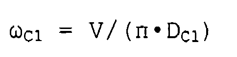
main pulley 5 be Dm and the effective diameters of the first and secondsubsidiary pulleys rope bodies 10 be V, then rotational frequency ωm of themain pulley 5 and rotational frequencies ωC1 and ωC2 of thesubsidiary pulleys 

- Rotational frequency ωBm of the
main bearings 4 and rotational frequencies ωB1 and ωB2 of thesubsidiary bearings 


- For example, if V = 120 m/min, Dm = 0.56 m, DC1 = 0.54 m, and DC2 = 0.52 m, then the rotational frequencies of the
main pulley 5 and thesubsidiary pulleys 


The rotational frequency of themain bearings 4 and the rotational frequencies of thesubsidiary bearings 


- Thus, the rotational frequencies of the
subsidiary bearings main bearings 4. In other words, the rotational speeds of thesubsidiary bearings cylindrical portion 5a are slow even if themain pulley 5 and thesubsidiary pulleys - The rotational frequency of the
main bearings 4 is approximately equal to the rotational frequency of conventional deflection pulleys in which subsidiary pulleys are not separated from a main pulley. Dimensions for mounting themain bearings 4 are also similar to those of conventional deflection pulleys. Thus, conventional deflection pulley rolling bearings can also be used for themain bearings 4 without modification. - In addition, the
main bearings 4 are chosen based on acting load, rotational frequency, frequency of activation, and desired service life, and rolling bearings, which are advantageous with regard to service life, are used for themain bearings 4 in a traction elevator since traveling speed is high and frequency of activation is also high. - On the other hand, sliding bearings, which are superior with regard to mounted dimensions, can be used instead of rolling bearings for the
subsidiary pulleys subsidiary pulleys - In a deflection pulley apparatus of this kind, because a
cylindrical portion 5a is disposed on themain pulley 5 andsubsidiary pulleys cylindrical portion 5a, differing types of the bearings can be used for themain bearings 4 and for thesubsidiary bearings
In particular, because rolling bearings are used for themain bearings 4 and sliding bearings are used for thesubsidiary bearings - Because the effective diameter of the
main pulley 5 and the effective diameters of the subsidiary pulleys 8 and 9 differ from each other, even if adeflection pulley 11 whose rotating shaft is not parallel is disposed adjacently, therope bodies 10 enter parallel to thegrooves rope bodies 10 and thegrooves - Next,
Figure 2 is a front elevation showing a deflection pulley apparatus according toEmbodiment 2 of the present invention partially sectioned. In Embodiment 1,single grooves main pulley 5 and the subsidiary pulleys 8 and 9, but in this example amain pulley 13 having twogrooves subsidiary pulley 14 having twogrooves main pulley 13 and thesubsidiary pulley 14. The rest of the configuration is similar to that of Embodiment 1. - In a deflection pulley apparatus of this kind, because the effective diameter of the
subsidiary pulley 14 and the effective diameter of themain pulley 13 differ from each other, the approach angles of therope bodies 10 onto thegrooves rope bodies 10 and thegrooves grooves main pulley 13 and thesubsidiary pulley 14, respectively, the number of parts is reduced, enabling productivity to be improved. - Next,
Figure 3 is a front elevation showing a deflection pulley apparatus according toEmbodiment 3 of the present invention partially sectioned. In this example, effective diameters of amain pulley 5 and subsidiary pulleys 8 and 9 are identical. The rest of the configuration is similar to that of Embodiment 1. - In a deflection pulley apparatus of this kind, wear and tear on the
rope bodies 10 and thegrooves rope bodies 10, etc., can be suppressed. In this case, since the rotational frequencies of thesubsidiary bearing cylindrical portion 5a are small enough to be practically ignored, it is also possible for the subsidiary pulleys 8 and 9 to be fitted over thecylindrical portion 5a directly without using sliding bearings for thesubsidiary bearings cylindrical portion 5a. - Next,
Figure 4 is a front elevation showing a deflection pulley apparatus according toEmbodiment 4 of the present invention partially sectioned. In the figure, acylindrical boss 20 is fitted overmain bearings 4 that are constituted by rolling bearings. Theboss 20 is disposed coaxially with ashaft 3 so as to surround theshaft 3, and is rotatable around theshaft 3. - A plurality of subsidiary pulleys 8, 9, and 21 are disposed on an outer portion of the
boss 20. The subsidiary pulleys 8, 9, and 21 are rotatable around theshaft 3, and each is independently rotatable relative to theboss 20.Grooves Subsidiary bearing boss 20 and the respective subsidiary pulleys 8, 9, and 21. Sliding bearings are used for each of thesubsidiary bearings - In a deflection pulley apparatus of this kind, because the
main bearings 4 that are constituted by rolling bearings are disposed between theshaft 3 and theboss 20, and thesubsidiary bearings boss 20 and the subsidiary pulleys 8, 9, and 21, width dimensions can be reduced while also being able to cope with high-speed rotation.
Because the effective diameters of the subsidiary pulleys 8, 9, and 21 differ from each other, even if adeflection pulley 11 whose rotating shaft is not parallel is disposed adjacently, therope bodies 10 enter parallel to thegrooves rope bodies 10 and thegrooves - Next,
Figure 5 is a front elevation showing a deflection pulley apparatus according toEmbodiment 5 of the present invention partially sectioned. InEmbodiment 4,single grooves subsidiary pulley 14 having twogrooves subsidiary pulley 22 having twogrooves Subsidiary bearings boss portion 20 and the subsidiary pulleys 14 and 22. The rest of the configuration is similar to that ofEmbodiment 4. - In a deflection pulley apparatus of this kind, because the effective diameters of the subsidiary pulleys 14 and 22 differ from each other, the approach angles of the
rope bodies 10 onto thegrooves rope bodies 10 and thegrooves grooves - Next,
Figure 6 is a front elevation showing a deflection pulley apparatus according toEmbodiment 6 of the present invention partially sectioned. In this example, effective diameters of subsidiary pulleys 8, 9, and 21 are identical. The rest of the configuration is similar to that ofEmbodiment 4. - In a deflection pulley apparatus of this kind, wear and tear on the
rope bodies 10 and thegrooves rope bodies 10, etc., can be suppressed. In this case, since the rotational frequencies of thesubsidiary bearing boss portion 20 are small enough to be practically ignored, it is also possible for the subsidiary pulleys 8, 9, and 21 to be fitted over theboss portion 20 directly without using sliding bearings for thesubsidiary bearings boss portion 20. - Moreover, in the above examples, a deflection pulley apparatus used in a traction elevator has been explained, but a deflection pulley apparatus according to the present invention may also be applied to devices other than elevators.
Claims (5)
- A deflection pulley apparatus comprising:a shaft;a main bearing that is fitted over the shaft;a main pulley having a cylindrical portion that is disposed coaxially with the shaft so as to surround the shaft, the main pulley being fitted over the main bearing; anda subsidiary pulley that is disposed on an outer portion of the cylindrical portion, and that is rotatable around the shaft and also rotatable relative to the main pulley.
- The deflection pulley apparatus according to Claim 1, further comprising a subsidiary bearing that is disposed between the cylindrical portion and the subsidiary pulley,
the main bearing being a rolling bearing, and the subsidiary bearing being a sliding bearing. - The deflection pulley apparatus according to Claim 1, wherein an effective diameter of the main pulley and an effective diameter of the subsidiary pulley differ from each other.
- A deflection pulley apparatus comprising:a shaft;a main bearing that is fitted over the shaft;a boss that is disposed coaxially with the shaft so as to surround the shaft, the boss being fitted over the main bearing;a plurality of subsidiary pulleys that are disposed on an outer portion of the boss, and that are rotatable around the shaft and also rotatable relative to the boss; anda plurality of subsidiary bearings that are respectively disposed between the boss and the subsidiary pulleys,the main bearing being a rolling bearing, and the subsidiary bearings being sliding bearings.
- The deflection pulley apparatus according to Claim 4, wherein effective diameters of the subsidiary pulleys differ from each other.
Applications Claiming Priority (1)
| Application Number | Priority Date | Filing Date | Title |
|---|---|---|---|
| PCT/JP2005/015129 WO2007020705A1 (en) | 2005-08-19 | 2005-08-19 | Deflection sheave device |
Publications (2)
| Publication Number | Publication Date |
|---|---|
| EP1916450A1 true EP1916450A1 (en) | 2008-04-30 |
| EP1916450A4 EP1916450A4 (en) | 2011-04-20 |
Family
ID=37757377
Family Applications (1)
| Application Number | Title | Priority Date | Filing Date |
|---|---|---|---|
| EP05780440A Withdrawn EP1916450A4 (en) | 2005-08-19 | 2005-08-19 | PULLEY DEVICE FOR RETURN |
Country Status (4)
| Country | Link |
|---|---|
| EP (1) | EP1916450A4 (en) |
| JP (1) | JP4814240B2 (en) |
| CN (1) | CN100443777C (en) |
| WO (1) | WO2007020705A1 (en) |
Cited By (4)
| Publication number | Priority date | Publication date | Assignee | Title |
|---|---|---|---|---|
| DE202015103087U1 (en) * | 2015-06-12 | 2016-09-19 | Schwartz Gmbh | idler pulley |
| WO2018187030A1 (en) * | 2017-04-03 | 2018-10-11 | National Oilwell Varco, L.P. | Hoisting and tensioning bearing saver |
| US10246303B2 (en) | 2015-02-12 | 2019-04-02 | Kone Corporation | Arrangement and elevator |
| US10670112B2 (en) | 2017-04-10 | 2020-06-02 | National Oilwell Varco, L.P. | Deadline anchor pigtail clamp |
Families Citing this family (4)
| Publication number | Priority date | Publication date | Assignee | Title |
|---|---|---|---|---|
| JP5288366B2 (en) * | 2007-09-03 | 2013-09-11 | 東芝エレベータ株式会社 | Brake release device for elevator hoisting machine and elevator system including the same |
| JP6118720B2 (en) * | 2013-12-19 | 2017-04-19 | 株式会社日立製作所 | Elevator equipment |
| JP6588136B1 (en) * | 2018-07-09 | 2019-10-09 | 東芝エレベータ株式会社 | Elevator heavy material carrying method and elevator apparatus |
| CN114084775B (en) * | 2021-12-17 | 2024-04-26 | 河南大亘计量检测研究院有限公司 | Elevator steel wire rope tension detection method and device, adjusting method and car pulley block |
Family Cites Families (8)
| Publication number | Priority date | Publication date | Assignee | Title |
|---|---|---|---|---|
| GB1121220A (en) * | 1966-10-10 | 1968-07-24 | Otis Elevator Co | Noise abating and traction improving elevator sheave |
| JPS5961179A (en) * | 1982-09-30 | 1984-04-07 | Fujitsu Ltd | Manufacture of bipolar semiconductor device |
| JPS5961179U (en) * | 1982-10-15 | 1984-04-21 | 三菱電機株式会社 | sheave |
| JPS6241422A (en) * | 1985-08-19 | 1987-02-23 | Fumitaka Hirozawa | Bearing mechanism |
| JP2809648B2 (en) * | 1988-09-28 | 1998-10-15 | 株式会社クラレ | Composite fiber with deodorant performance |
| JPH0291215U (en) * | 1988-12-29 | 1990-07-19 | ||
| JPH0761745A (en) * | 1993-08-18 | 1995-03-07 | Otis Elevator Co | Hoist type elevator |
| FI111622B (en) * | 1999-01-27 | 2003-08-29 | Kone Corp | Drive lift and use of break disk |
-
2005
- 2005-08-19 CN CNB2005800318564A patent/CN100443777C/en not_active Expired - Fee Related
- 2005-08-19 EP EP05780440A patent/EP1916450A4/en not_active Withdrawn
- 2005-08-19 JP JP2007530887A patent/JP4814240B2/en not_active Expired - Fee Related
- 2005-08-19 WO PCT/JP2005/015129 patent/WO2007020705A1/en not_active Ceased
Cited By (8)
| Publication number | Priority date | Publication date | Assignee | Title |
|---|---|---|---|---|
| US10246303B2 (en) | 2015-02-12 | 2019-04-02 | Kone Corporation | Arrangement and elevator |
| DE202015103087U1 (en) * | 2015-06-12 | 2016-09-19 | Schwartz Gmbh | idler pulley |
| EP3103755A1 (en) * | 2015-06-12 | 2016-12-14 | Schwartz GmbH | Deflection sheave |
| WO2018187030A1 (en) * | 2017-04-03 | 2018-10-11 | National Oilwell Varco, L.P. | Hoisting and tensioning bearing saver |
| GB2575206A (en) * | 2017-04-03 | 2020-01-01 | Nat Oilwell Varco Lp | Hoisting and tensioning bearing saver |
| US11279601B2 (en) | 2017-04-03 | 2022-03-22 | National Oilwell Varco, L.P. | Hoisting and tensioning bearing saver |
| GB2575206B (en) * | 2017-04-03 | 2022-05-18 | Nat Oilwell Varco Lp | Hoisting and tensioning bearing saver |
| US10670112B2 (en) | 2017-04-10 | 2020-06-02 | National Oilwell Varco, L.P. | Deadline anchor pigtail clamp |
Also Published As
| Publication number | Publication date |
|---|---|
| EP1916450A4 (en) | 2011-04-20 |
| WO2007020705A1 (en) | 2007-02-22 |
| CN101023286A (en) | 2007-08-22 |
| JP4814240B2 (en) | 2011-11-16 |
| JPWO2007020705A1 (en) | 2009-02-19 |
| CN100443777C (en) | 2008-12-17 |
Similar Documents
| Publication | Publication Date | Title |
|---|---|---|
| EP1591403B1 (en) | Traction elevator system having multiple machines | |
| EP2391568B1 (en) | Elevator system | |
| US7857103B2 (en) | Elevator system | |
| JPH06255959A (en) | Elevator motor arranged in counter weight | |
| EP1916450A1 (en) | Deflection sheave device | |
| EP1818303B1 (en) | Machine room-less elevator. | |
| CN101142132A (en) | elevator equipment | |
| JP2010116254A (en) | Elevator system | |
| EP2263962B1 (en) | Elevator hoisting machine | |
| WO2007129385A1 (en) | Elevator device | |
| KR102092078B1 (en) | Hanging sheave applied to 2: 1 rope fastening system for elevator | |
| EP2019073B1 (en) | Elevator device | |
| EP1961688A1 (en) | Elevator device | |
| KR100816178B1 (en) | Divert pulley device | |
| CN110891890B (en) | Guide wheel in traction tool driving device | |
| EP2089305B1 (en) | Drive for lifts | |
| CN205740128U (en) | Crane gear cable drum rope processing device | |
| EP1966073B1 (en) | Elevator traction sheave | |
| EP1870370B1 (en) | Elevator device | |
| JP4031202B2 (en) | Power transmission and bearing device for drums | |
| EP1862420B1 (en) | Elevator apparatus | |
| CN217172927U (en) | A hoist device for fan hoist and mount construction | |
| KR20250171843A (en) | Hanging sheave for elevator | |
| JP2018177434A (en) | Elevator hoisting machine | |
| KR200177080Y1 (en) | Sheave shaft support device of elevator hoist |
Legal Events
| Date | Code | Title | Description |
|---|---|---|---|
| PUAI | Public reference made under article 153(3) epc to a published international application that has entered the european phase |
Free format text: ORIGINAL CODE: 0009012 |
|
| 17P | Request for examination filed |
Effective date: 20070328 |
|
| AK | Designated contracting states |
Kind code of ref document: A1 Designated state(s): DE |
|
| DAX | Request for extension of the european patent (deleted) | ||
| RBV | Designated contracting states (corrected) |
Designated state(s): DE |
|
| A4 | Supplementary search report drawn up and despatched |
Effective date: 20110321 |
|
| STAA | Information on the status of an ep patent application or granted ep patent |
Free format text: STATUS: THE APPLICATION HAS BEEN WITHDRAWN |
|
| 18W | Application withdrawn |
Effective date: 20110801 |