EP1916137A1 - Fahrzeugaufbau - Google Patents
Fahrzeugaufbau Download PDFInfo
- Publication number
- EP1916137A1 EP1916137A1 EP07018443A EP07018443A EP1916137A1 EP 1916137 A1 EP1916137 A1 EP 1916137A1 EP 07018443 A EP07018443 A EP 07018443A EP 07018443 A EP07018443 A EP 07018443A EP 1916137 A1 EP1916137 A1 EP 1916137A1
- Authority
- EP
- European Patent Office
- Prior art keywords
- vehicle body
- body according
- sealing element
- vehicle
- longitudinal
- Prior art date
- Legal status (The legal status is an assumption and is not a legal conclusion. Google has not performed a legal analysis and makes no representation as to the accuracy of the status listed.)
- Granted
Links
Images


Classifications
-
- B—PERFORMING OPERATIONS; TRANSPORTING
- B60—VEHICLES IN GENERAL
- B60J—WINDOWS, WINDSCREENS, NON-FIXED ROOFS, DOORS, OR SIMILAR DEVICES FOR VEHICLES; REMOVABLE EXTERNAL PROTECTIVE COVERINGS SPECIALLY ADAPTED FOR VEHICLES
- B60J5/00—Doors
- B60J5/04—Doors arranged at the vehicle sides
- B60J5/06—Doors arranged at the vehicle sides slidable; foldable
- B60J5/062—Doors arranged at the vehicle sides slidable; foldable for utility vehicles or public transport
- B60J5/065—Doors arranged at the vehicle sides slidable; foldable for utility vehicles or public transport with non-rigid elements, e.g. side curtains
Definitions
- the invention relates to a vehicle body with movable in the vehicle longitudinal direction walls, in particular designed as tarpaulins and the like Lijns109wandept, which are arranged on formed from a hollow profile and connected thereto rail profiles, and arranged on this sealing elements upper longitudinal straps of the vehicle body, wherein at least one with respect to the Vehicle center located outside region of the longitudinal belt has at least one slot-shaped open longitudinal recess.
- Such vehicle bodies in particular for commercial vehicles, are in many cases provided with movable side walls in order to facilitate the loading and unloading accordingly.
- the movable side walls can be formed in the simple case by, for example, tarpaulins, which are suspended in the vehicle longitudinal direction displaceable on the upper longitudinal straps of the frame of the vehicle body.
- the side walls are formed by rigid, also displaceable in the vehicle longitudinal direction displaceable suspended on the upper longitudinal straps of the vehicle body side rests. Both possibilities of the side walls can also be subsequently attached to the corresponding vehicle.
- the structure of the roof in particular also designed to be displaceable in the vehicle longitudinal direction, so that a loading of the vehicle from above via these openings is possible.
- the framework of the vehicle body must therefore be designed so that each of the aforementioned types of wall or even a movable or rigid roof can be safely and tightly mounted.
- the longitudinal straps of the vehicle body are in spite of a span length of about 13 m to be stretched in the required rigidity and load capacity, but with the lowest possible weight available to not adversely affect the payload of the vehicle.
- a generic vehicle body is described, with movable in the vehicle longitudinal direction walls, in particular as slides or Plan trained Lijns109wandept that are suspended from formed from a central hollow profile and connected to this rail profiles and formed on this sealing profiles upper longitudinal straps of the vehicle body.
- This vehicle body is characterized in that the upper longitudinal belt of the frame of the vehicle body is formed by a one-piece continuous drawing profile, which has a hollow and a plurality of connected thereto at the top and the outside, substantially a rectangular cross-sectional profile, connected to the formation of running. or guide rails serving vertically oriented profile webs comprises.
- the vehicle structure according to the prior art is further characterized in that the profile web lying on the outside in relation to the vehicle center is provided with an outwardly projecting bead, which in turn is provided with a slot-shaped longitudinal recess in which a strip-shaped seal is provided via an edge bead the suspension of the longitudinally displaceable side wall of the vehicle body is suspended.
- this generic vehicle structure it is necessary to introduce the sealing element in the slot-shaped open longitudinal recess and to feed over the entire length of about 13 m in the longitudinal belt. This is generally realized with, for example, cable winches, wherein in the assembly of such vehicle bodies, the sealing element is at the upper edge of the vehicle body at a height of about 4 m and the installation with a crane very complex and only with great effort is possible.
- Another disadvantage of the known prior art is seen that the insertion of the sealing element over the entire length of the vehicle body is associated with a high expenditure of force, at the same time the sealing element itself is exposed to a certain damage or impairment.
- Another disadvantage is that a once retracted in the longitudinal belt sealing element during assembly of the vehicle body can be damaged, but will not be changed later due to the increased time and mechanical complexity.
- This disadvantage also relates to already mounted vehicle superstructures, where, for example, after improper loading or unloading or even after accidents, the side wall or the sealing element can be damaged and the side wall is changeable, the sealing element but not or only with increased effort.
- the enormous financial, temporal and technical complexity of the replacement of the sealing element ultimately prevents selbiges.
- the generic vehicle structure still has a further disadvantage, which consists in that by retracting the sealing element over the entire length of the vehicle body, this does not fully abut the L Lucass109wandungen and thus not completely seals.
- Another disadvantage is seen that the sealing element, due to the mechanical stress during assembly, but also by possible thermal stresses during use wrinkled or porous and so the sealing function is no longer fully realized in full or completely impossible.
- the invention which has set itself the task of overcoming the disadvantages of the known prior art, and to show a vehicle body, which is inexpensive and economical to produce, in a uniform design with optional either side tarpaulins or side stanchions and a rigid or sliding Roof full; can be equipped circumferentially sealed, and in which a sealing element under constant force, the side tarpaulins or side stanchions and the rigid or sliding roofs sealing, is also retrofittable.
- the vehicle body with sliding in the vehicle longitudinal direction walls in particular as tarpaulins and the like formed L Lucass109wandept, which are arranged on a hollow profile and connected to this rail profiles, and arranged on this sealing elements upper longitudinal straps of the vehicle body, wherein at least one lying with respect to the vehicle center on the outside Section of the longitudinal belt has at least one slot-shaped open longitudinal recess, characterized in that the sealing element has at least partially a holding element which orthogonal to the vehicle longitudinal direction positively into the longitudinal recess can be introduced and the sealing element orthogonally detachable on the longitudinal belt can be arranged.
- the sealing element subsequently to clean, sealing and firmly attached to an already fully assembled vehicle body.
- the visible surface of this sealing element is thus during assembly the vehicle body is not damaged, while at the same time an extremely fast and cost-effective installation of the vehicle body itself is possible.
- the holding element is arranged on the side opposite the longitudinal belt side of the sealing element, so that the sealing element is easily introduced into the communicating longitudinal recess of the longitudinal belt.
- the holding element is integrally connected to the sealing element, which on the one hand positively influences the strength and stability and on the other hand also reduces the manufacturing cost accordingly.
- the holding element is materially connected to the sealing element, which is possible for example by a known per se bonding.
- the retaining element is non-positively releasably connected to the sealing element, which can be realized by appropriately in operative connection with each other locking.
- the holding element is arranged approximately at a right angle to the sealing element, so that the assembly in the opposite longitudinal recess of the longitudinal belt is possible quickly, easily and safely. Furthermore, it is advantageously considered that the holding element is arranged at an angle of approximately 1 to 20 °, preferably 1 to 8 °, on the sealing element, which is advantageous in particular when attached to longitudinal straps in which rigid or displaceable roofs are to be introduced.
- the holding element has at least one latching element, which is designed such that the sealing element is frictionally connected via the holding element with the longitudinal recess of the longitudinal belt.
- the dimensioning of the locking element corresponds to the length of the sealing element to be installed as well as the side tarpaulins or side stanchions to be covered by the sealing element.
- the retaining element has at least one hollow chamber, which is formed so that the sealing element is arranged quickly and without force in the longitudinal recess of the longitudinal belt and placed there tightly sealing.
- the holding element has at least two spaced-apart locking elements, wherein it is within the scope of the invention that these two locking elements are integrally mounted on the sealing element or formed as two different, separate or independent locking elements are.
- the holding element and / or the sealing element has at least one reinforcing element, so that the requirements for the stability and strength of the vehicle body as well as the corresponding standards can be met.
- the vehicle structure according to the invention is also distinguished by the fact that the sealing element has a wall thickness which is approximately constant over its cross section, so that, for example, no wrinkling and thus cancellation of the sealing effect can occur under thermal loads.
- the sealing element has approximately a concave and / or convex outer contour, so that the vehicle structure according to the invention, whether on the side tarpaulin or side stanchions, but also in rigid or slidably arranged roofs, at any time in the edge region is sealed.
- the sealing element at least partially on a decorative element. It has proven to be advantageous that the decorative element is arranged on the opposite side of the holding element of the sealing element, so that this is easily visible over the entire width or height of the vehicle body at any time.
- This decorative element which can be applied by a known printing, painting, foil lamination and the like, in addition to an additional advertising space on the vehicle structure according to the invention but also that additional additional functions can be integrated.
- the decorative element is designed as a reflector strip, light-emitting element, fluorescent element and the like, so that existing or future safety requirements for a vehicle body can be realized easily, inexpensively and optically effectively.
- the sealing element and / or the retaining element is made of a polymeric material.
- the polymeric material from the group of polyolefins, polystyrenes, styrene copolymers, polyvinyl chlorides, polycarbonates, polyesters, polyamides, ethylene vinyl acetates and the like is selected.
- the polymeric material is selected from the group of silicone rubbers or from the group of natural and / or synthetic rubbers.
- the sealing element and / or the holding element is made of a crosslinkable material.
- the sealing element and / or the retaining element is made of a metallic material.
- This metallic material is selected from the group of steels, stainless steels, light metals and the like and, in addition to the sealing effect, simultaneously increases the stability and improves the appearance of the vehicle body according to the invention.
- the sealing element and / or the retaining element is made of a polymeric and a metallic material.
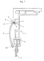
- FIG. 1 shows a vehicle body with walls which are displaceable in the vehicle longitudinal direction, in particular longitudinal side walls 2 designed as tarpaulins and the like, which are attached to a hollow profile and to runner profiles 3 connected thereto arranged on this arranged sealing elements 6 upper longitudinal straps 1 of the vehicle body are arranged, wherein at least one with respect to the vehicle center outside region 5 of the longitudinal belt 1 has at least one slot-shaped open longitudinal recess 4.
- the longitudinal belt 1 is approximately L-shaped and has various hollow chambers or longitudinal recesses.
- a sealing element 6 is arranged in the slot-shaped longitudinal recess 4, which is located in relation to the vehicle center outside region 5 of the longitudinal belt 1.
- the sealing element 6 has a holding element 7 arranged over the entire length, which is inserted into the longitudinal recess 4 in a force-locking manner orthogonal to the vehicle longitudinal axis and the sealing element 6 is arranged orthogonally releasably on the longitudinal belt 1.
- the holding element 7 is arranged in this embodiment approximately at a right angle to the sealing element 6 and has two opposing locking elements 71.
- the holding element 7 has in this embodiment, a hollow chamber 8, which is arranged approximately centrally and prismatic in this. Through the hollow chamber 8 of the holding element 7, it is easily possible to introduce the sealing element 6 in the slot-shaped longitudinal recess 4.
- the longitudinal recess 4 is arranged horizontally and orthogonal to the vehicle longitudinal direction in this embodiment.
- the sealing element 6 is convex in this embodiment and covers both the longitudinal belt 1 and the rollers mounted in the rails 3 longitudinal side walls 2, which are formed in this embodiment as a plan.
- the sealing element 6 On its side opposite the holding element 7, the sealing element 6 has a decorative element 10, which is formed in the lower area over the entire length as a reflector strip.
- FIG. 2 shows a further vehicle structure according to the invention, the longitudinal belt 1 being shown in broken lines only in sections.
- the longitudinal belt 1 has at least one outer region in relation to the vehicle center, in which a slot-shaped longitudinal recess 4 is arranged.
- An approximately convex sealing element 6 is introduced via at least one locking element 71 designed as a retaining element 7 in the longitudinal recess 4 of the longitudinal belt 1.
- the holding element 7 of the sealing element 6 consists in this embodiment of two spaced-apart locking elements 71.
- a further locking element 9 is arranged on the holding element 7.
- This locking element 9 is in this embodiment of polymeric material, which is orthogonal to the existing of a metallic material sealing element 6 fixed to the vehicle longitudinal direction frictionally in the longitudinal recess 4 of the longitudinal belt 1.
- the sealing element 6 has, in this example, over its entire, the holding member 7 opposite surface, a decorative element 10, which can be applied by a known printing, lamination, Folienkaschtechnik and the like.
- FIG. 3 shows a further sectional view through a sealing element 6 of the vehicle body according to the invention.
- the sealing element 6 has a wall thickness different over its cross section.
- the holding element 7 is formed in this embodiment by a, a hollow chamber 8 forming web 72 on which a latching element 71 is arranged.
- the sealing element 6 is preassembled in the longitudinal recess 4 of the longitudinal belt 1, not shown here, via the web 72, while the final assembly is effected by the horizontal insertion of the locking element 71 into the hollow chamber 8 formed by the web 72.
- the sealing element 6 is made in this embodiment of a polymeric material which is selected for example from the group of polyvinyl chlorides.
- the sealing means 6 in its interior at least one introduced in the longitudinal direction reinforcing means 11, which may be formed, for example, as glass fibers, metallic fibers and the like.
- reinforcing means 11 which may be formed, for example, as glass fibers, metallic fibers and the like.
- Materialausappelisme 12 are arranged, which affect the material requirements and thus the price of the sealing element 6, while maintaining strength, due to the reinforcing means 11, according positively positive.
- the holding element 7 of the sealing element 6 is arranged in this embodiment approximately at a right angle to the sealing element 6, so that it is not shown in horizontal, in the installed state outwardly facing longitudinal recesses 4 of the longitudinal belt 1 can be introduced.
- the holding element 7 in such a way that it is horizontally arranged, not shown here, longitudinal recesses 4 of the longitudinal belt 1 can be introduced, which are formed in the installed state parallel to the vehicle longitudinal direction downwards or upwards.
- the sealing element 6 thus has, at least in sections, a holding element 7 which can be introduced into the longitudinal recess 4 in a force-locking manner orthogonally to the vehicle longitudinal direction and the sealing element 6 can be arranged orthogonally detachably on the longitudinal belt 1.
- the longitudinal recess 4 may be formed parallel to the vehicle longitudinal direction, so that the sealing element 6 can be introduced into a longitudinal recess 4, not shown here, which is arranged approximately parallel to the track profiles 3.
Landscapes
- Engineering & Computer Science (AREA)
- Mechanical Engineering (AREA)
- Seal Device For Vehicle (AREA)
- Transition And Organic Metals Composition Catalysts For Addition Polymerization (AREA)
- Body Structure For Vehicles (AREA)
Abstract
Description
- Die Erfindung betrifft einen Fahrzeugaufbau mit in Fahrzeuglängsrichtung verschieblichen Wandungen, insbesondere als Planen und dergleichen ausgebildeten Längsseitenwandungen, die an aus einem Hohlprofil und an dieses angeschlossenen Laufschienenprofilen, sowie an dieses angeordneten Dichtelementen gebildeten oberen Längsgurten des Fahrzeugaufbaus angeordnet sind, wobei wenigstens ein in Bezug auf die Fahrzeugmitte außen liegender Bereich des Längsgurtes wenigstens eine schlitzförmig geöffnete Längsausnehmung aufweist.
- Derartige Fahrzeugaufbauten, insbesondere für Nutzfahrzeuge, sind in vielen Fällen mit beweglichen Seitenwandungen versehen, um das Be- und Entladen entsprechend zu erleichtern. Dabei können die beweglichen Seitenwandungen im einfachen Falle durch beispielsweise Planen gebildet sein, die in Fahrzeuglängsrichtung verschieblich an den oberen Längsgurten des Rahmens des Fahrzeugaufbaus aufgehängt sind. Es ist jedoch auch möglich, dass die Seitenwandungen durch starre, gleichfalls in Fahrzeuglängsrichtung verschieblich an den oberen Längsgurten des Fahrzeugaufbaus aufgehängte Seitenrungen gebildet sind. Beide Möglichkeiten der Seitenwandungen können auch jeweils nachträglich an dem entsprechenden Fahrzeug angebracht werden.
Ferner wird bei Nutzfahrzeugen dieser Art häufig der Aufbau insbesondere des Daches ebenfalls in Fahrzeuglängsrichtung verschiebbar gestaltet, so dass auch eine Beladung des Fahrzeuges von oben her über diese Öffnungen möglich ist.
Der Rahmen des Fahrzeugaufbaus muss daher so gestaltet sein, dass jede der vorgenannten Wandungsarten bzw. auch ein bewegliches bzw. starres Dach sicher und dicht angebracht werden kann. Die Längsgurte des Fahrzeugaufbaues sind trotz einer zu überspannenden Pritschenlänge von ca. 13 m in der erforderlichen Starrheit und Tragfähigkeit, aber mit einem möglichst geringen Gewicht zur Verfügung zu stellen, um die Nutzlast des Fahrzeuges nicht negativ zu beeinträchtigen. - In der
DE 3929425 A1 wird ein gattungsgemäßer Fahrzeugaufbau beschrieben, mit in Fahrzeuglängsrichtung verschieblichen Wandungen, insbesondere als Schieberungen oder Planen ausgebildeten Längsseitenwandungen, die an aus einem zentralen Hohlprofil und an dieses angeschlossenen Laufschienenprofilen sowie an dieses angeschlossenen Dichtprofilen gebildeten oberen Längsgurten des Fahrzeugaufbaues aufgehängt sind. Dieser Fahrzeugaufbau ist dadurch gekennzeichnet, dass der obere Längsgurt des Rahmens des Fahrzeugaufbaus durch ein einteiliges fortlaufendes Ziehprofil gebildet ist, welches einen oben und außen liegend angeordneten, im Wesentlichen ein rechteckiges Querschnittprofil aufweisenden, Hohlträger und eine Vielzahl an diesen angeschlossener, zur Bildung von Lauf- oder Führungsschienen dienender, vertikal gerichteter Profilstege umfasst.
Der Fahrzeugaufbau nach dem Stand der Technik ist weiterhin dadurch gekennzeichnet, dass der in Bezug auf die Fahrzeugmitte außen liegende Profilsteg mit einer nach außen vorspringenden Wulst versehen ist, die ihrerseits mit einer schlitzförmig geöffneten Längsausnehmung versehen ist, in der über einen Randwulst eine streifenförmige Abdichtung für die Aufhängung der längs verschieblichen Seitenwandung des Fahrzeugaufbaus aufgehängt ist.
Bei diesem gattungsgemäßen Fahrzeugaufbau ist es erforderlich, das Dichtelement in die schlitzförmig geöffnete Längsausnehmung einzuführen und über die gesamte Länge von ca. 13 m in den Längsgurt einzuziehen. Dies wird im Allgemeinen mit beispielsweise Seilwinden realisiert, wobei bei der Montage derartiger Fahrzeugaufbauten sich das Dichtelement an der oberen Kante des Fahrzeugaufbaus in einer Höhe von ca. 4 m befindet und die Montage mit einem Kran sehr aufwändig und nur mit hohem Kraftaufwand nur möglich ist.
Weiterhin nachteilig bei dem bekannten Stand der Technik wird gesehen, dass das Einziehen des Dichtelementes über die gesamte Länge des Fahrzeugaufbaus mit einem hohen Kraftaufwand verbunden ist, wobei gleichzeitig das Dichtelement selbst einer gewissen Schädigung bzw. Beeinträchtigung ausgesetzt ist.
Ein weiterer Nachteil besteht darin, dass ein einmal in den Längsgurt eingezogenes Dichtelement während der Montage des Fahrzeugaufbaues beschädigt werden kann, jedoch aufgrund des erhöhten zeitlichen sowie mechanischen Aufwandes später nicht mehr gewechselt wird. Dieser Nachteil betrifft auch bereits montierte Fahrzeugaufbauten, wo beispielsweise nach unsachgemäßer Be- bzw. Entladung oder auch nach Unfällen die Seitenwandung bzw. das Dichtelement beschädigt werden können und die Seitenwandung wechselbar ist, das Dichtelement jedoch nicht bzw. nur mit erhöhtem Aufwand. Der enorme finanzielle, zeitliche und technische Aufwand des Austausches des Dichtelementes verhindert letztlich selbiges. - Der gattungsgemäße Fahrzeugaufbau weist jedoch noch einen weiteren Nachteil auf, der darin besteht, dass durch das Einziehen des Dichtelementes über die gesamte Länge des Fahrzeugaufbaues dieses nicht voll an den Längsseitenwandungen anliegt und somit nicht komplett abdichtet.
Weiterhin nachteilig wird gesehen, dass das Dichtelement, bedingt durch die mechanische Belastung bei der Montage, aber auch durch mögliche thermische Belastungen während des Einsatzes faltig bzw. porös und so die Dichtfunktion nicht mehr voll umfänglich realisiert bzw. gänzlich unmöglich wird. - Hier setzt die Erfindung ein, die sich die Aufgabe gestellt hat, die Nachteile des bekannten Standes der Technik zu überwinden, und einen Fahrzeugaufbau aufzuzeigen, der kostengünstig und wirtschaftlich herstellbar ist, der in einheitlicher Ausführung wahlweise mit Seitenplanen oder Seitenrungen sowie mit einem starren oder verschieblichen Dach voll; umfänglich abgedichtet ausgestattet werden kann, und bei dem ein Dichtelement unter konstanter Kraft, die Seitenplanen bzw. Seitenrungen sowie die starren oder verschieblichen Dächer abdichtend, auch nachträglich montierbar ist.
- Erfindungsgemäß wird dies durch die kennzeichnenden Merkmale des Anspruches 1 gelöst. Weitere vorteilhafte Ausgestaltungen sind in den Unteransprüchen beschrieben.
- Der Fahrzeugaufbau mit in Fahrzeuglängsrichtung verschieblichen Wandungen, insbesondere als Planen und dergleichen ausgebildeten Längsseitenwandungen, die an aus einem Hohlprofil und an dieses angeschlossenen Laufschienenprofilen, sowie an dieses angeordneten Dichtelementen gebildeten oberen Längsgurten des Fahrzeugaufbaus angeordnet sind, wobei wenigstens ein in Bezug auf die Fahrzeugmitte außen liegender Bereich des Längsgurtes wenigstens eine schlitzförmig geöffnete Längsausnehmung aufweist, ist dadurch gekennzeichnet, dass das Dichtelement wenigstens abschnittsweise ein Halteelement aufweist, welches orthogonal zur Fahrzeuglängsrichtung kraftschlüssig in die Längsausnehmung einbringbar und das Dichtelement orthogonal lösbar am Längsgurt anordenbar ist.
- Somit ist es bei dem erfindungsgemäßen Fahrzeugaufbau erstmals möglich, das Dichtelement nachträglich an einem bereits fertig montierten Fahrzeugaufbau sauber, abdichtend und fest anzubringen. Die Sichtfläche dieses Dichtelementes wird somit während der Montage des Fahrzeugaufbaus nicht beschädigt, während gleichzeitig eine extrem schnelle und kostengünstige Montage des Fahrzeugaufbaus an sich möglich ist.
- Weiterhin vorteilhaft wird gesehen, dass das Halteelement an der dem Längsgurt gegenüberliegenden Seite des Dichtelementes angeordnet ist, so dass das Dichtelement in die kommunizierende Längsausnehmung des Längsgurtes problemlos einbringbar ist.
- In einer weiteren vorteilhaften Ausgestaltung ist das Halteelement einstückig mit dem Dichtelement verbunden, was einerseits die Festigkeit und Stabilität positiv beeinflusst und andererseits auch die Herstellungskosten entsprechend reduziert.
In einer weiteren ebenfalls vorteilhaften Ausgestaltungsform ist das Halteelement stoffschlüssig mit dem Dichtelement verbunden, was beispielsweise durch eine an sich bekannte Verklebung möglich ist.
In einer ebenfalls vorteilhaften Ausgestaltungsform ist das Halteelement kraftschlüssig lösbar mit dem Dichtelement verbunden, was durch entsprechend in Wirkverbindung miteinander stehende Verrastungen realisierbar ist. - Ebenfalls vorteilhaft wird gesehen, dass das Halteelement in etwa einem rechten Winkel zum Dichtelement angeordnet ist, so dass die Montage in die gegenüberliegende Längsausnehmung des Längsgurtes schnell, einfach und sicher möglich ist.
Weiterhin vorteilhaft wird gesehen, dass das Halteelement in einem Winkel von etwa 1 bis 20°, vorzugsweise 1 bis 8° am Dichtelement angeordnet ist, welches insbesondere bei Anbringung an Längsgurten, bei denen starre oder verschiebliche Dächer einzubringen sind, vorteilhaft ist.
In einer weiteren vorteilhaften Ausgestaltung weist das Halteelement wenigstens ein Rastelement auf, welches so ausgebildet ist, dass das Dichtelement über das Halteelement kraftschlüssig mit der Längsausnehmung des Längsgurtes verbindbar ist. Die Dimensionierung des Rastelementes entspricht der zu verbauenden Länge des Dichtelementes sowie der durch das Dichtelement abzudeckenden Seitenplanen bzw. Seitenrungen. - In einer weiteren vorteilhaften Ausgestaltungsform weist das Halteelement wenigstens eine Hohlkammer auf, die so ausgebildet ist, dass das Dichtelement schnell und ohne Kraftaufwand in der Längsausnehmung des Längsgurtes einbringbar und dort fest abdichtend angeordnet ist.
- Dies kann vorteilhafterweise auch dadurch erreicht werden, dass das Halteelement wenigstens zwei voneinander beabstandet angeordnete Rastelemente aufweist, wobei es im Rahmen der Erfindung liegt, dass diese zwei Rastelemente einstückig am Dichtelement angebracht sind bzw. auch als zwei unterschiedliche, voneinander getrennte bzw. unabhängige Rastelemente ausgebildet sind.
- In einer weiteren vorteilhaften Ausgestaltungsform weist das Halteelement und/oder das Dichtelement wenigstens ein Verstärkungselement auf, so dass den Anforderungen an die Stabilität und Festigkeit des Fahrzeugaufbaus sowie den entsprechenden Normen Genüge getan werden kann.
- Der erfindungsgemäße Fahrzeugaufbau zeichnet sich auch dadurch aus, dass das Dichtelement eine über seinen Querschnitt etwa konstante Wandstärke aufweist, so dass beispielsweise bei thermischen Belastungen keine Faltenbildung und damit eine Aufhebung der Dichtwirkung auftreten kann.
- Weiterhin vorteilhaft wird gesehen, dass das Dichtelement in etwa eine konkave und/oder konvexe Außenkontur aufweist, so dass der erfindungsgemäße Fahrzeugaufbau, sei es an den Seitenplanen bzw. Seitenrungen, aber auch bei starren oder verschieblich angeordneten Dächern, jederzeit im Randbereich abgedichtet ist.
- In einer weiteren vorteilhaften Ausbildung weist das Dichtelement wenigstens abschnittsweise ein Dekorelement auf.
Es hat sich als vorteilhaft herausgestellt, dass das Dekorelement auf der dem Halteelement gegenüberliegenden Seite des Dichtelementes angeordnet ist, so dass dies über die gesamte Breite bzw. Höhe des Fahrzeugaufbaues jederzeit problemlos sichtbar ist. Dieses Dekorelement, welches durch eine an sich bekannte Bedruckung, Lackierung, Folienkaschierung und dergleichen aufbringbar ist, ermöglicht neben einer zusätzlichen Werbefläche auf dem erfindungsgemäßen Fahrzeugaufbau aber auch, dass weitere zusätzliche Funktionen integrierbar sind.
In einer ebenfalls vorteilhaften Ausgestaltungsform ist das Dekorelement als Reflektorstreifen, Leuchtelement, fluoreszierendes Element und dergleichen ausgebildet, so dass bestehende bzw. zukünftige Sicherheitsanforderungen an einen Fahrzeugaufbau problemlos, kostengünstig und optisch wirksam realisierbar sind. - In einer vorteilhaften Ausgestaltung des erfindungsgemäßen Fahrzeugaufbaues ist das Dichtelement und/oder das Halteelement aus einem polymeren Werkstoff hergestellt. Hiermit lassen sich niedrige Herstellungskosten, die Farbenvielfalt sowie die geometrischen Ausgestaltungen für derartige Fahrzeugaufbauten problemlos realisieren, wobei der polymere Werkstoff aus der Gruppe der Polyolefine, Polystyrole, Styrol-Copolymere, Polyvinylchloride, Polycarbonate, Polyester, Polyamide, Ethylenvinylacetate und dergleichen ausgewählt ist.
Es liegt jedoch auch im Rahmen der Erfindung, dass der polymere Werkstoff ausgewählt ist aus der Gruppe der Silikonkautschuke bzw. aus der Gruppe der Natur- und/oder Synthesekautschuke.
In einer weiteren vorteilhaften Ausgestaltung ist das Dichtelement und/oder das Halteelement aus einem vernetzbaren Werkstoff hergestellt. - Weiterhin vorteilhaft wird gesehen, dass das Dichtelement und/oder das Halteelement aus einem metallischen Werkstoff hergestellt ist. Dieser metallische Werkstoff ist ausgewählt aus der Gruppe der Stähle, der Edelstähle, der Leichtmetalle und dergleichen und erhöht neben der abdichtenden Wirkung gleichzeitig die Stabilität und verbessert die Optik des erfindungsgemäßen Fahrzeugaufbaus.
Es liegt jedoch auch im Rahmen der Erfindung, dass das Dichtelement und/oder das Halteelement aus einem polymeren und einem metallischen Werkstoff hergestellt ist. - Die Erfindung soll nun an diesen nicht einschränkenden Ausführungsbeispielen näher beschrieben werden.
Es zeigen: - Figur 1
- Schnittdarstellung des erfindungsgemäßen Fahrzeugaufbaus
- Figur 2
- Schnittdarstellung eines weiteren erfindungsgemäßen Fahrzeugaufbaus
- Figur 3
- Schnittdarstellung eines Dichtelementes des erfindungsgemäßen Fahrzeugaufbaus
- In Figur 1 ist ein Fahrzeugaufbau mit in Fahrzeuglängsrichtung verschieblichen Wandungen, insbesondere als Planen und dergleichen ausgebildeten Längsseitenwandungen 2, die an aus einem Hohlprofil und an dieses angeschlossenen Laufschienenprofilen 3 sowie an dieses angeordneten Dichtelementen 6 gebildeten oberen Längsgurten 1 des Fahrzeugaufbaus angeordnet sind, wobei wenigstens ein in Bezug auf die Fahrzeugmitte außen liegender Bereich 5 des Längsgurtes 1 wenigstens eine schlitzförmig geöffnete Längsausnehmung 4 aufweist. Der Längsgurt 1 ist etwa L-förmig ausgebildet und weist verschiedene Hohlkammern bzw. Längsausnehmungen auf.
In der schlitzförmigen Längsausnehmung 4, welche sich im in Bezug auf die Fahrzeugmitte außen liegenden Bereich 5 des Längsgurtes 1 befindet, ist ein Dichtelement 6 angeordnet. Das Dichtelement 6 weist in diesem Ausführungsbeispiel ein über die gesamte Länge angeordnetes Halteelement 7 auf, welches orthogonal zur Fahrzeuglängsachse kraftschlüssig in die Längsausnehmung 4 eingebracht und das Dichtelement 6 orthogonal lösbar am Längsgurt 1 angeordnet ist. Das Halteelement 7 ist in diesem Ausführungsbeispiel in etwa einem rechten Winkel zum Dichtelement 6 angeordnet und weist zwei einander gegenüberliegenden Rastelemente 71 auf. Das Halteelement 7 weist in diesem Ausführungsbeispiel eine Hohlkammer 8 auf, die etwa zentral und prismatisch in diesen angeordnet ist. Durch die Hohlkammer 8 des Halteelementes 7 ist es problemlos möglich, das Dichtelement 6 in die schlitzförmige Längsausnehmung 4 einzubringen. Die Längsausnehmung 4 ist in diesem Ausführungsbeispiel horizontal und orthogonal zur Fahrzeuglängsrichtung angeordnet. Das Dichtelement 6 ist in diesem Ausführungsbeispiel konvex ausgebildet und überdeckt sowohl den Längsgurt 1 als auch die über Rollen in den Laufschienenprofilen 3 befestigten Längsseitenwandungen 2, welche in diesem Ausführungsbeispiel als Planen ausgebildet sind. Das Dichtelement 6 weist auf seiner dem Halteelement 7 gegenüberliegend angeordneten Seite ein Dekorelement 10 auf, welches im unteren Bereich über die gesamte Länge als Reflektorstreifen ausgebildet ist. - In Figur 2 ist ein weiterer erfindungsgemäßer Fahrzeugaufbau abgebildet, wobei der Längsgurt 1 nur abschnittsweise gestrichelt dargestellt ist. Der Längsgurt 1 weist wenigstens einen in Bezug auf die Fahrzeugmitte außen liegenden Bereich auf, in dem eine schlitzförmig geöffnete Längsausnehmung 4 angeordnet ist. Ein etwa konvex ausgebildetes Dichtelement 6 ist über wenigstens ein als Rastelement 71 ausgebildetes Halteelement 7 in der Längsausnehmung 4 des Längsgurtes 1 eingebracht. Das Halteelement 7 des Dichtelementes 6 besteht in diesem Ausführungsbeispiel aus zwei voneinander beabstandet angeordneten Rastelementen 71. Zur optimalen Fixierung des Dichtelementes 6 in der Längsausnehmung 4 des Längsgurtes 1 ist ein weiteres Rastelement 9 am Halteelement 7 angeordnet. Dieses Rastelement 9 besteht in diesem Ausführungsbeispiel aus polymeren Werkstoff, der das aus einem metallischen Werkstoff bestehende Dichtelement 6 orthogonal zur Fahrzeuglängsrichtung kraftschlüssig in der Längsausnehmung 4 des Längsgurtes 1 fixiert.
Das Dichtelement 6 weist in diesem Beispiel eine über seine gesamte, dem Halteelement 7 gegenüberliegende, Fläche ein Dekorelement 10 auf, welches durch eine an sich bekannte Bedruckung, Kaschierung, Folienkaschierung und dergleichen aufbringbar ist. Durch diese zusätzliche optische Gestaltung des Dichtelementes 6 können kundenspezifische bzw. sicherheitsrelevante Designs kostengünstig und wirtschaftlich am Fahrzeugaufbau angebracht werden. - In Figur 3 ist eine weitere Schnittdarstellung durch ein Dichtelement 6 des erfindungsgemäßen Fahrzeugaufbaus dargestellt. Das Dichtelement 6 weist in diesem Ausführungsbeispiel eine über seinen Querschnitt unterschiedliche Wandstärke auf. Das Halteelement 7 ist in diesem Ausführungsbeispiel durch einen, eine Hohlkammer 8 bildenden, Steg 72 gebildet, an dem ein Rastelement 71 angeordnet ist. Das Dichtelement 6 wird in der hier nicht dargestellten Längsausnehmung 4 des Längsgurtes 1 über den Steg 72 vormontiert, während die Endmontage durch das horizontale Einschieben des Rastelementes 71 in die durch den Steg 72 gebildete Hohlkammer 8 erfolgt. Das Dichtelement 6 ist in diesem Ausführungsbeispiel aus einem polymeren Werkstoff hergestellt, der ausgewählt ist beispielsweise aus der Gruppe der Polyvinylchloride. Zur besseren Stabilisierung sowohl der mechanischen als auch der thermischen Eigenschaften weist das Dichtmittel 6 in seinem Inneren wenigstens ein in Längsrichtung eingebrachtes Verstärkungsmittel 11 auf, welches beispielsweise als Glasfasern, metallische Fasern und dergleichen ausgebildet sein kann.
An der Außenkontur des Dichtelementes 6 sind Materialausnehmungen 12 angeordnet, welche den Materialbedarf und damit den Preis des Dichtelementes 6, bei gleich bleibender Festigkeit, bedingt durch die Verstärkungsmittel 11, entsprechend positiv beeinflussen. - Das Halteelement 7 des Dichtelementes 6 ist in diesem Ausführungsbeispiel in etwa einem rechten Winkel zum Dichtelement 6 angeordnet, so dass es in hier nicht dargestellten horizontale, im Einbauzustand nach außen weisende, Längsausnehmungen 4 des Längsgurtes 1 einbringbar ist.
Es liegt jedoch auch im Rahmen der Erfindung, das Halteelement 7 so auszubilden, dass es in horizontal angeordnete, hier nicht dargestellte, Längsausnehmungen 4 des Längsgurtes 1 einbringbar ist, die im Einbauzustand parallel zur Fahrzeuglängsrichtung nach unten bzw. nach oben weisend ausgebildet sind. - Das Dichtelement 6 weist somit wenigstens abschnittsweise ein Halteelement 7 auf, welches orthogonal zur Fahrzeuglängsrichtung kraftschlüssig in die Längsausnehmung 4 einbringbar und das Dichtelement 6 orthogonal lösbar am Längsgurt 1 anordenbar ist. Die Längsausnehmung 4 kann dabei parallel zur Fahrzeuglängsrichtung ausgebildet sein, so dass das Dichtelement 6 in eine etwa parallel zu den Laufschienenprofilen 3 angeordnete hier nicht dargestellte Längsausnehmung 4 einbringbar ist.
Claims (25)
- Fahrzeugaufbau mit in Fahrzeuglängsrichtung verschieblichen Wandungen, insbesondere als Planen und dergleichen ausgebildeten Längsseitenwandungen (2), die an aus einem Hohlprofil und an dieses angeschlossenen Laufschienenprofilen (3), sowie an dieses angeordneten Dichtelementen (6) gebildeten oberen Längsgurten (1) des Fahrzeugaufbaus angeordnet sind, wobei wenigstens ein in Bezug auf die Fahrzeugmitte außen liegender Bereich (5) des Längsgurtes (1) wenigstens eine schlitzförmig geöffnete Längsausnehmung (4) aufweist,
dadurch gekennzeichnet, dass das Dichtelement (6) wenigstens abschnittsweise ein Halteelement (7) aufweist, welches orthogonal zur Fahrzeuglängsrichtung kraftschlüssig in die Längsausnehmung (4) einbringbar und das Dichtelement (6) orthogonal lösbar am Längsgurt (1) anordenbar ist. - Fahrzeugaufbau nach Anspruch 1, dadurch gekennzeichnet, dass das Halteelement (7) an der dem Längsgurt (1) gegenüberliegenden Seite des Dichtelementes (6) angeordnet ist.
- Fahrzeugaufbau nach einem der vorhergehenden Ansprüche, dadurch gekennzeichnet, dass das Halteelement (7) einstückig mit dem Dichtelement (6) verbunden ist.
- Fahrzeugaufbau nach einem der vorhergehenden Ansprüche, dadurch gekennzeichnet, dass das Halteelement (6) stoffschlüssig mit dem Dichtelement (6) verbunden ist.
- Fahrzeugaufbau nach einem der vorhergehenden Ansprüche, dadurch gekennzeichnet, dass das Halteelement (7) kraftschlüssig lösbar mit dem Dichtelement (6) verbunden ist.
- Fahrzeugaufbau nach einem der vorhergehenden Ansprüche, dadurch gekennzeichnet, dass das Halteelement (7) in etwa einem rechten Winkel zum Dichtelement (6) angeordnet ist.
- Fahrzeugaufbau nach einem der vorhergehenden Ansprüche, dadurch gekennzeichnet, dass das Halteelement (7) in einem Winkel von etwa 1 bis 20 Grad, vorzugsweise 1 bis 8 Grad am Dichtelement (6) angeordnet ist.
- Fahrzeugaufbau nach einem der vorhergehenden Ansprüche, dadurch gekennzeichnet, dass das Halteelement (7) wenigstens ein Rastelement (71) aufweist.
- Fahrzeugaufbau nach einem der vorhergehenden Ansprüche, dadurch gekennzeichnet, dass das Halteelement (7) wenigstens eine Hohlkammer (8) aufweist.
- Fahrzeugaufbau nach einem der vorhergehenden Ansprüche, dadurch gekennzeichnet, dass das Halteelement (7) wenigstens zwei voneinander beabstandet angeordnete Rastelemente (71, 9) aufweist.
- Fahrzeugaufbau nach einem der vorhergehenden Ansprüche, dadurch gekennzeichnet, dass das Halteelement (7) und/oder das Dichtelement (6) wenigstens ein Verstärkungselement (11) aufweist.
- Fahrzeugaufbau nach einem der vorhergehenden Ansprüche, dadurch gekennzeichnet, dass das Dichtelement (6) eine über seinen Querschnitt etwa konstante Wandstärke aufweist.
- Fahrzeugaufbau nach einem der vorhergehenden Ansprüche, dadurch gekennzeichnet, dass das Dichtelement (6) eine etwa konkave und/oder konvexe Außenkontur aufweist.
- Fahrzeugaufbau nach einem der vorhergehenden Ansprüche, dadurch gekennzeichnet, dass das Dichtelement (6) wenigstens abschnittsweise eine Dekorelement (10) aufweist.
- Fahrzeugaufbau nach Anspruch 14, dadurch gekennzeichnet, dass die Dekorelement (10) auf der dem Halteelement (7) gegenüberliegenden Seite des Dichtelementes (6) angeordnet ist.
- Fahrzeugaufbau nach einem der vorhergehenden Ansprüche, dadurch gekennzeichnet, dass die Dekorelement (10) durch eine an sich bekannte Bedruckung, Lackierung, Folienkaschierung aufbringbar ist.
- Fahrzeugaufbau nach einem der vorhergehenden Ansprüche, dadurch gekennzeichnet, dass die Dekorelement (10) als Reflektorstreifen, Leuchtelement, fluoreszierendes Element und dergleichen ausgebildet ist.
- Fahrzeugaufbau nach einem der vorhergehenden Ansprüche, dadurch gekennzeichnet, dass das Dichtelement (6) und/oder das Halteelement (7) aus einem polymeren Werkstoff hergestellt ist.
- Fahrzeugaufbau nach einem der vorhergehenden Ansprüche, dadurch gekennzeichnet, dass das Dichtelement (6) und/oder das Halteelement (7) aus einem vernetzbaren Werkstoff besteht.
- Fahrzeugaufbau nach Anspruch 18 bis 19, dadurch gekennzeichnet, dass der polymere Werkstoff ausgewählt ist aus der Gruppe der Polyolefine, Polystyrole, Styrol-Copolymere, Polyvinylchloride, Polycarbonate, Polyester, Polyamide, Ethylenvinylacetate und dergleichen.
- Fahrzeugaufbau nach Anspruch 18 bis 19, dadurch gekennzeichnet, dass der polymere Werkstoff ausgewählt ist aus der Gruppe der Silikonkautschuke.
- Fahrzeugaufbau nach Anspruch 18 bis 19, dadurch gekennzeichnet, dass der polymere Werkstoff ausgewählt ist aus der Gruppe der Natur- und/ oder Synthesekautschuke.
- Fahrzeugaufbau nach Anspruch 1 bis 17, dadurch gekennzeichnet, dass das Dichtelement (6) und/oder das Halteelement (7) aus einem metallischen Werkstoff hergestellt ist.
- Fahrzeugaufbau nach Anspruch 23, dadurch gekennzeichnet, dass der metallische Werkstoff ausgewählt ist aus der Gruppe der Stähle, der Edelstähle, der Leichtmetalle und dergleichen.
- Fahrzeugaufbau nach einem der vorhergehenden Ansprüche, dadurch gekennzeichnet, dass das Dichtelement (6) und/oder das Halteelement (7) aus einem polymeren und einem metallischen Werkstoff hergestellt ist.
Priority Applications (1)
| Application Number | Priority Date | Filing Date | Title |
|---|---|---|---|
| EP10008079A EP2241465A3 (de) | 2006-09-26 | 2007-09-20 | Fahrzeugaufbau |
Applications Claiming Priority (1)
| Application Number | Priority Date | Filing Date | Title |
|---|---|---|---|
| DE202006014886U DE202006014886U1 (de) | 2006-09-26 | 2006-09-26 | Fahrzeugaufbau |
Related Child Applications (1)
| Application Number | Title | Priority Date | Filing Date |
|---|---|---|---|
| EP10008079.5 Division-Into | 2010-08-03 |
Publications (2)
| Publication Number | Publication Date |
|---|---|
| EP1916137A1 true EP1916137A1 (de) | 2008-04-30 |
| EP1916137B1 EP1916137B1 (de) | 2011-01-19 |
Family
ID=39047240
Family Applications (2)
| Application Number | Title | Priority Date | Filing Date |
|---|---|---|---|
| EP10008079A Withdrawn EP2241465A3 (de) | 2006-09-26 | 2007-09-20 | Fahrzeugaufbau |
| EP07018443A Not-in-force EP1916137B1 (de) | 2006-09-26 | 2007-09-20 | Fahrzeugaufbau |
Family Applications Before (1)
| Application Number | Title | Priority Date | Filing Date |
|---|---|---|---|
| EP10008079A Withdrawn EP2241465A3 (de) | 2006-09-26 | 2007-09-20 | Fahrzeugaufbau |
Country Status (3)
| Country | Link |
|---|---|
| EP (2) | EP2241465A3 (de) |
| AT (1) | ATE495928T1 (de) |
| DE (2) | DE202006014886U1 (de) |
Cited By (4)
| Publication number | Priority date | Publication date | Assignee | Title |
|---|---|---|---|---|
| USD750544S1 (en) * | 2014-05-15 | 2016-03-01 | Edscha Trailer Systems Gmbh | Guide rails for a tarpaulin cover of a commercial vehicle |
| USD751024S1 (en) * | 2014-05-15 | 2016-03-08 | Edscha Trailer Systems Gmbh | Guide rails for a tarpaulin cover of a commercial vehicle |
| USD753576S1 (en) * | 2014-05-15 | 2016-04-12 | Edscha Trailer Systems Gmbh | Guide rails for a tarpaulin cover of a commercial vehicle |
| CN105599575A (zh) * | 2016-03-11 | 2016-05-25 | 安徽省地坤汽车天窗科技有限公司 | 一种汽车天窗的高稳定性导轨结构 |
Citations (6)
| Publication number | Priority date | Publication date | Assignee | Title |
|---|---|---|---|---|
| GB2123466A (en) * | 1982-07-15 | 1984-02-01 | Fruehauf Corp | Curtain sided railway goods vehicle |
| EP0292098A1 (de) * | 1987-05-21 | 1988-11-23 | The Eastern Company | Zugangssystem und Verriegelungsaufbau für LKW-Anhänger mit Seitenplanen |
| US4828316A (en) * | 1987-05-14 | 1989-05-09 | Utility Trailer Manufacturing Company | Vehicle curtain quick release device |
| EP0736404A2 (de) | 1995-04-05 | 1996-10-09 | Croce, Mattia Celso, dba SPRING di CROCE MATTIA CELSO & C. S.n.c. | Profilführungselement für Wagendecken |
| DE20216370U1 (de) * | 2002-10-23 | 2003-02-27 | Vertical Vision GmbH & Co. KG, 51065 Köln | Schutzverschweißung |
| EP1502789A2 (de) | 2003-08-01 | 2005-02-02 | Severino Dona' | Führung für bewegbare Abdeckungen |
Family Cites Families (6)
| Publication number | Priority date | Publication date | Assignee | Title |
|---|---|---|---|---|
| DE3929425A1 (de) * | 1989-08-30 | 1991-03-14 | Scharwaechter Gmbh Co Kg | Fahrzeugaufbau |
| GB9414201D0 (en) * | 1994-07-14 | 1994-08-31 | Montracon Ltd | Curtain-sides vehicles |
| DE9417255U1 (de) * | 1994-10-27 | 1996-02-22 | Robert Orten GmbH u. Co. Fahrzeugbau -vertrieb, 54470 Bernkastel-Kues | Lastwagen mit Hub-Senk-Dach |
| AU711235B2 (en) * | 1996-08-08 | 1999-10-07 | Krueger Transport Equipment Pty Ltd | Weather shielding curtain-sided trailers |
| DE19644081A1 (de) * | 1996-10-31 | 1998-05-07 | Gross Aluminium Gmbh | Aufbau für Lastwagen und Anhänger mit Dachgurten |
| KR100496662B1 (ko) * | 2003-04-11 | 2005-06-17 | 동서물류 주식회사 | 화물차의 적재함커버 자동개폐장치 |
-
2006
- 2006-09-26 DE DE202006014886U patent/DE202006014886U1/de not_active Expired - Lifetime
-
2007
- 2007-09-20 AT AT07018443T patent/ATE495928T1/de active
- 2007-09-20 DE DE502007006296T patent/DE502007006296D1/de active Active
- 2007-09-20 EP EP10008079A patent/EP2241465A3/de not_active Withdrawn
- 2007-09-20 EP EP07018443A patent/EP1916137B1/de not_active Not-in-force
Patent Citations (6)
| Publication number | Priority date | Publication date | Assignee | Title |
|---|---|---|---|---|
| GB2123466A (en) * | 1982-07-15 | 1984-02-01 | Fruehauf Corp | Curtain sided railway goods vehicle |
| US4828316A (en) * | 1987-05-14 | 1989-05-09 | Utility Trailer Manufacturing Company | Vehicle curtain quick release device |
| EP0292098A1 (de) * | 1987-05-21 | 1988-11-23 | The Eastern Company | Zugangssystem und Verriegelungsaufbau für LKW-Anhänger mit Seitenplanen |
| EP0736404A2 (de) | 1995-04-05 | 1996-10-09 | Croce, Mattia Celso, dba SPRING di CROCE MATTIA CELSO & C. S.n.c. | Profilführungselement für Wagendecken |
| DE20216370U1 (de) * | 2002-10-23 | 2003-02-27 | Vertical Vision GmbH & Co. KG, 51065 Köln | Schutzverschweißung |
| EP1502789A2 (de) | 2003-08-01 | 2005-02-02 | Severino Dona' | Führung für bewegbare Abdeckungen |
Cited By (4)
| Publication number | Priority date | Publication date | Assignee | Title |
|---|---|---|---|---|
| USD750544S1 (en) * | 2014-05-15 | 2016-03-01 | Edscha Trailer Systems Gmbh | Guide rails for a tarpaulin cover of a commercial vehicle |
| USD751024S1 (en) * | 2014-05-15 | 2016-03-08 | Edscha Trailer Systems Gmbh | Guide rails for a tarpaulin cover of a commercial vehicle |
| USD753576S1 (en) * | 2014-05-15 | 2016-04-12 | Edscha Trailer Systems Gmbh | Guide rails for a tarpaulin cover of a commercial vehicle |
| CN105599575A (zh) * | 2016-03-11 | 2016-05-25 | 安徽省地坤汽车天窗科技有限公司 | 一种汽车天窗的高稳定性导轨结构 |
Also Published As
| Publication number | Publication date |
|---|---|
| EP2241465A2 (de) | 2010-10-20 |
| EP1916137B1 (de) | 2011-01-19 |
| EP2241465A3 (de) | 2012-04-18 |
| DE502007006296D1 (de) | 2011-03-03 |
| ATE495928T1 (de) | 2011-02-15 |
| DE202006014886U1 (de) | 2008-02-07 |
Similar Documents
| Publication | Publication Date | Title |
|---|---|---|
| DE102011103319B4 (de) | In ein Schiebedach oder ein Abdunklungssystem integrierte Umgebungsbeleuchtung | |
| WO2011134894A1 (de) | Fahrzeugrolloanordnung, baugruppe mit einer fahrzeugrolloanordnung, und dachanordnung | |
| EP1886854A1 (de) | Manuelles Fensterrollo mit automatischem Rückzug | |
| EP1781483B1 (de) | Dichtleiste für rahmenlose seitenfenster von kraftwagen | |
| DE102010017960A1 (de) | Fensterrollo für ein vieleckförmiges Fenster einer Fahrzeugtür eines Kraftfahrzeugs | |
| EP1916137B1 (de) | Fahrzeugaufbau | |
| DE102011075843A1 (de) | Rollosystem | |
| EP2874837B1 (de) | Schiebehimmel für ein kraftfahrzeug | |
| EP1867509A2 (de) | Fahrzeugaufbau für insbesondere Lastkraftwagen | |
| DE3836687A1 (de) | Dachzierleiste fuer ein kraftfahrzeug | |
| EP2285611A2 (de) | Cabriolet-fahrzeug mit einem innenhimmel | |
| DE102018111548A1 (de) | Verdunkelungsvorrichtung für ein Kraftfahrzeug, Führungsschiene, Fahrzeugdach und Kraftfahrzeug | |
| DE102014010962A1 (de) | Verdeck für ein öffnungsfähiges Fahrzeugdach | |
| DE102012102116B4 (de) | Baugruppe mit einer Rollobahn, und Dachanordnung | |
| DE102009025120A1 (de) | Führungsvorrichtung für eine Vorhangabdunkelungsvorrichtung | |
| DE202011110682U1 (de) | Struktur für ein Schiebedach, Schiebedachsystem, Lastfahrzeug mit Schiebedachsystem Curtainsider Anhänger mit einem Schiebedachsystem | |
| EP1680298B1 (de) | Cabriolet-fahrzeug | |
| EP4377546B1 (de) | Tor | |
| EP1847418A1 (de) | Ladegutsicherung an Transportfahrzeugen | |
| EP2990238B1 (de) | Dichtungsanordnung sowie mit einer dichtungsanordnung versehener planenaufbau | |
| DE4116223A1 (de) | Kraftfahrzeug mit einem abnehmbaren, festen aufsetzdach | |
| DE10321342B3 (de) | Überrollschutzsystem für ein Kraftfahrzeug | |
| DE102005021117A1 (de) | Kraftfahrzeug | |
| DE10024237A1 (de) | Kederlose Befestigungsanordnung eines Formhimmels an der Dachöffnung eines Fahrzeugs | |
| DE3718840C1 (en) | Window lifter for motor vehicles |
Legal Events
| Date | Code | Title | Description |
|---|---|---|---|
| PUAI | Public reference made under article 153(3) epc to a published international application that has entered the european phase |
Free format text: ORIGINAL CODE: 0009012 |
|
| AK | Designated contracting states |
Kind code of ref document: A1 Designated state(s): AT BE BG CH CY CZ DE DK EE ES FI FR GB GR HU IE IS IT LI LT LU LV MC MT NL PL PT RO SE SI SK TR |
|
| AX | Request for extension of the european patent |
Extension state: AL BA HR MK RS |
|
| 17P | Request for examination filed |
Effective date: 20080818 |
|
| 17Q | First examination report despatched |
Effective date: 20080926 |
|
| AKX | Designation fees paid |
Designated state(s): AT BE BG CH CY CZ DE DK EE ES FI FR GB GR HU IE IS IT LI LT LU LV MC MT NL PL PT RO SE SI SK TR |
|
| GRAP | Despatch of communication of intention to grant a patent |
Free format text: ORIGINAL CODE: EPIDOSNIGR1 |
|
| GRAS | Grant fee paid |
Free format text: ORIGINAL CODE: EPIDOSNIGR3 |
|
| GRAA | (expected) grant |
Free format text: ORIGINAL CODE: 0009210 |
|
| AK | Designated contracting states |
Kind code of ref document: B1 Designated state(s): AT BE BG CH CY CZ DE DK EE ES FI FR GB GR HU IE IS IT LI LT LU LV MC MT NL PL PT RO SE SI SK TR |
|
| REG | Reference to a national code |
Ref country code: GB Ref legal event code: FG4D Free format text: NOT ENGLISH |
|
| REG | Reference to a national code |
Ref country code: CH Ref legal event code: EP |
|
| REG | Reference to a national code |
Ref country code: IE Ref legal event code: FG4D Free format text: LANGUAGE OF EP DOCUMENT: GERMAN |
|
| REF | Corresponds to: |
Ref document number: 502007006296 Country of ref document: DE Date of ref document: 20110303 Kind code of ref document: P |
|
| REG | Reference to a national code |
Ref country code: DE Ref legal event code: R096 Ref document number: 502007006296 Country of ref document: DE Effective date: 20110303 |
|
| REG | Reference to a national code |
Ref country code: NL Ref legal event code: VDEP Effective date: 20110119 |
|
| LTIE | Lt: invalidation of european patent or patent extension |
Effective date: 20110119 |
|
| PG25 | Lapsed in a contracting state [announced via postgrant information from national office to epo] |
Ref country code: SE Free format text: LAPSE BECAUSE OF FAILURE TO SUBMIT A TRANSLATION OF THE DESCRIPTION OR TO PAY THE FEE WITHIN THE PRESCRIBED TIME-LIMIT Effective date: 20110119 Ref country code: PT Free format text: LAPSE BECAUSE OF FAILURE TO SUBMIT A TRANSLATION OF THE DESCRIPTION OR TO PAY THE FEE WITHIN THE PRESCRIBED TIME-LIMIT Effective date: 20110519 Ref country code: ES Free format text: LAPSE BECAUSE OF FAILURE TO SUBMIT A TRANSLATION OF THE DESCRIPTION OR TO PAY THE FEE WITHIN THE PRESCRIBED TIME-LIMIT Effective date: 20110430 Ref country code: LT Free format text: LAPSE BECAUSE OF FAILURE TO SUBMIT A TRANSLATION OF THE DESCRIPTION OR TO PAY THE FEE WITHIN THE PRESCRIBED TIME-LIMIT Effective date: 20110119 Ref country code: GR Free format text: LAPSE BECAUSE OF FAILURE TO SUBMIT A TRANSLATION OF THE DESCRIPTION OR TO PAY THE FEE WITHIN THE PRESCRIBED TIME-LIMIT Effective date: 20110420 Ref country code: IS Free format text: LAPSE BECAUSE OF FAILURE TO SUBMIT A TRANSLATION OF THE DESCRIPTION OR TO PAY THE FEE WITHIN THE PRESCRIBED TIME-LIMIT Effective date: 20110519 Ref country code: LV Free format text: LAPSE BECAUSE OF FAILURE TO SUBMIT A TRANSLATION OF THE DESCRIPTION OR TO PAY THE FEE WITHIN THE PRESCRIBED TIME-LIMIT Effective date: 20110119 |
|
| REG | Reference to a national code |
Ref country code: IE Ref legal event code: FD4D |
|
| PG25 | Lapsed in a contracting state [announced via postgrant information from national office to epo] |
Ref country code: BG Free format text: LAPSE BECAUSE OF FAILURE TO SUBMIT A TRANSLATION OF THE DESCRIPTION OR TO PAY THE FEE WITHIN THE PRESCRIBED TIME-LIMIT Effective date: 20110419 Ref country code: FI Free format text: LAPSE BECAUSE OF FAILURE TO SUBMIT A TRANSLATION OF THE DESCRIPTION OR TO PAY THE FEE WITHIN THE PRESCRIBED TIME-LIMIT Effective date: 20110119 Ref country code: PL Free format text: LAPSE BECAUSE OF FAILURE TO SUBMIT A TRANSLATION OF THE DESCRIPTION OR TO PAY THE FEE WITHIN THE PRESCRIBED TIME-LIMIT Effective date: 20110119 Ref country code: SI Free format text: LAPSE BECAUSE OF FAILURE TO SUBMIT A TRANSLATION OF THE DESCRIPTION OR TO PAY THE FEE WITHIN THE PRESCRIBED TIME-LIMIT Effective date: 20110119 Ref country code: CY Free format text: LAPSE BECAUSE OF FAILURE TO SUBMIT A TRANSLATION OF THE DESCRIPTION OR TO PAY THE FEE WITHIN THE PRESCRIBED TIME-LIMIT Effective date: 20110119 Ref country code: NL Free format text: LAPSE BECAUSE OF FAILURE TO SUBMIT A TRANSLATION OF THE DESCRIPTION OR TO PAY THE FEE WITHIN THE PRESCRIBED TIME-LIMIT Effective date: 20110119 |
|
| PG25 | Lapsed in a contracting state [announced via postgrant information from national office to epo] |
Ref country code: DK Free format text: LAPSE BECAUSE OF FAILURE TO SUBMIT A TRANSLATION OF THE DESCRIPTION OR TO PAY THE FEE WITHIN THE PRESCRIBED TIME-LIMIT Effective date: 20110119 Ref country code: EE Free format text: LAPSE BECAUSE OF FAILURE TO SUBMIT A TRANSLATION OF THE DESCRIPTION OR TO PAY THE FEE WITHIN THE PRESCRIBED TIME-LIMIT Effective date: 20110119 Ref country code: IE Free format text: LAPSE BECAUSE OF FAILURE TO SUBMIT A TRANSLATION OF THE DESCRIPTION OR TO PAY THE FEE WITHIN THE PRESCRIBED TIME-LIMIT Effective date: 20110119 |
|
| PLBE | No opposition filed within time limit |
Free format text: ORIGINAL CODE: 0009261 |
|
| STAA | Information on the status of an ep patent application or granted ep patent |
Free format text: STATUS: NO OPPOSITION FILED WITHIN TIME LIMIT |
|
| PG25 | Lapsed in a contracting state [announced via postgrant information from national office to epo] |
Ref country code: SK Free format text: LAPSE BECAUSE OF FAILURE TO SUBMIT A TRANSLATION OF THE DESCRIPTION OR TO PAY THE FEE WITHIN THE PRESCRIBED TIME-LIMIT Effective date: 20110119 Ref country code: CZ Free format text: LAPSE BECAUSE OF FAILURE TO SUBMIT A TRANSLATION OF THE DESCRIPTION OR TO PAY THE FEE WITHIN THE PRESCRIBED TIME-LIMIT Effective date: 20110119 Ref country code: RO Free format text: LAPSE BECAUSE OF FAILURE TO SUBMIT A TRANSLATION OF THE DESCRIPTION OR TO PAY THE FEE WITHIN THE PRESCRIBED TIME-LIMIT Effective date: 20110119 |
|
| 26N | No opposition filed |
Effective date: 20111020 |
|
| PG25 | Lapsed in a contracting state [announced via postgrant information from national office to epo] |
Ref country code: IT Free format text: LAPSE BECAUSE OF FAILURE TO SUBMIT A TRANSLATION OF THE DESCRIPTION OR TO PAY THE FEE WITHIN THE PRESCRIBED TIME-LIMIT Effective date: 20110119 |
|
| REG | Reference to a national code |
Ref country code: DE Ref legal event code: R097 Ref document number: 502007006296 Country of ref document: DE Effective date: 20111020 |
|
| BERE | Be: lapsed |
Owner name: REHAU A.G. + CO Effective date: 20110930 |
|
| PG25 | Lapsed in a contracting state [announced via postgrant information from national office to epo] |
Ref country code: MC Free format text: LAPSE BECAUSE OF NON-PAYMENT OF DUE FEES Effective date: 20110930 |
|
| REG | Reference to a national code |
Ref country code: CH Ref legal event code: PL |
|
| GBPC | Gb: european patent ceased through non-payment of renewal fee |
Effective date: 20110920 |
|
| PG25 | Lapsed in a contracting state [announced via postgrant information from national office to epo] |
Ref country code: BE Free format text: LAPSE BECAUSE OF NON-PAYMENT OF DUE FEES Effective date: 20110930 |
|
| PG25 | Lapsed in a contracting state [announced via postgrant information from national office to epo] |
Ref country code: CH Free format text: LAPSE BECAUSE OF NON-PAYMENT OF DUE FEES Effective date: 20110930 Ref country code: LI Free format text: LAPSE BECAUSE OF NON-PAYMENT OF DUE FEES Effective date: 20110930 |
|
| PG25 | Lapsed in a contracting state [announced via postgrant information from national office to epo] |
Ref country code: GB Free format text: LAPSE BECAUSE OF NON-PAYMENT OF DUE FEES Effective date: 20110920 |
|
| PG25 | Lapsed in a contracting state [announced via postgrant information from national office to epo] |
Ref country code: MT Free format text: LAPSE BECAUSE OF FAILURE TO SUBMIT A TRANSLATION OF THE DESCRIPTION OR TO PAY THE FEE WITHIN THE PRESCRIBED TIME-LIMIT Effective date: 20110119 |
|
| PG25 | Lapsed in a contracting state [announced via postgrant information from national office to epo] |
Ref country code: LU Free format text: LAPSE BECAUSE OF NON-PAYMENT OF DUE FEES Effective date: 20110920 |
|
| PG25 | Lapsed in a contracting state [announced via postgrant information from national office to epo] |
Ref country code: TR Free format text: LAPSE BECAUSE OF FAILURE TO SUBMIT A TRANSLATION OF THE DESCRIPTION OR TO PAY THE FEE WITHIN THE PRESCRIBED TIME-LIMIT Effective date: 20110119 |
|
| PG25 | Lapsed in a contracting state [announced via postgrant information from national office to epo] |
Ref country code: HU Free format text: LAPSE BECAUSE OF FAILURE TO SUBMIT A TRANSLATION OF THE DESCRIPTION OR TO PAY THE FEE WITHIN THE PRESCRIBED TIME-LIMIT Effective date: 20110119 |
|
| REG | Reference to a national code |
Ref country code: FR Ref legal event code: PLFP Year of fee payment: 10 |
|
| REG | Reference to a national code |
Ref country code: FR Ref legal event code: PLFP Year of fee payment: 11 |
|
| REG | Reference to a national code |
Ref country code: FR Ref legal event code: PLFP Year of fee payment: 12 |
|
| PGFP | Annual fee paid to national office [announced via postgrant information from national office to epo] |
Ref country code: AT Payment date: 20200911 Year of fee payment: 14 |
|
| REG | Reference to a national code |
Ref country code: DE Ref legal event code: R081 Ref document number: 502007006296 Country of ref document: DE Owner name: REHAU INDUSTRIES SE & CO. KG, DE Free format text: FORMER OWNER: REHAU AG + CO, 95111 REHAU, DE |
|
| REG | Reference to a national code |
Ref country code: AT Ref legal event code: MM01 Ref document number: 495928 Country of ref document: AT Kind code of ref document: T Effective date: 20210920 |
|
| PG25 | Lapsed in a contracting state [announced via postgrant information from national office to epo] |
Ref country code: AT Free format text: LAPSE BECAUSE OF NON-PAYMENT OF DUE FEES Effective date: 20210920 |
|
| PGFP | Annual fee paid to national office [announced via postgrant information from national office to epo] |
Ref country code: FR Payment date: 20220728 Year of fee payment: 16 |
|
| PGFP | Annual fee paid to national office [announced via postgrant information from national office to epo] |
Ref country code: DE Payment date: 20230930 Year of fee payment: 17 |
|
| PG25 | Lapsed in a contracting state [announced via postgrant information from national office to epo] |
Ref country code: FR Free format text: LAPSE BECAUSE OF NON-PAYMENT OF DUE FEES Effective date: 20230930 |
|
| REG | Reference to a national code |
Ref country code: DE Ref legal event code: R119 Ref document number: 502007006296 Country of ref document: DE |
|
| PG25 | Lapsed in a contracting state [announced via postgrant information from national office to epo] |
Ref country code: DE Free format text: LAPSE BECAUSE OF NON-PAYMENT OF DUE FEES Effective date: 20250401 |