EP1915916B1 - Formteil für Zehensandale - Google Patents
Formteil für Zehensandale Download PDFInfo
- Publication number
- EP1915916B1 EP1915916B1 EP06022288A EP06022288A EP1915916B1 EP 1915916 B1 EP1915916 B1 EP 1915916B1 EP 06022288 A EP06022288 A EP 06022288A EP 06022288 A EP06022288 A EP 06022288A EP 1915916 B1 EP1915916 B1 EP 1915916B1
- Authority
- EP
- European Patent Office
- Prior art keywords
- moulded part
- part according
- base portion
- areas
- raised
- Prior art date
- Legal status (The legal status is an assumption and is not a legal conclusion. Google has not performed a legal analysis and makes no representation as to the accuracy of the status listed.)
- Not-in-force
Links
- 210000003371 toe Anatomy 0.000 claims description 28
- 210000002683 foot Anatomy 0.000 claims description 17
- 238000000465 moulding Methods 0.000 description 23
- 238000000926 separation method Methods 0.000 description 14
- 230000002093 peripheral effect Effects 0.000 description 7
- 239000000463 material Substances 0.000 description 2
- 230000001133 acceleration Effects 0.000 description 1
- 230000001427 coherent effect Effects 0.000 description 1
- 230000000694 effects Effects 0.000 description 1
- 210000001255 hallux Anatomy 0.000 description 1
- 238000003780 insertion Methods 0.000 description 1
- 230000037431 insertion Effects 0.000 description 1
- 229920001296 polysiloxane Polymers 0.000 description 1
- 239000012858 resilient material Substances 0.000 description 1
- 230000000284 resting effect Effects 0.000 description 1
- 230000008093 supporting effect Effects 0.000 description 1
- 238000010408 sweeping Methods 0.000 description 1
Images

Classifications
-
- A—HUMAN NECESSITIES
- A43—FOOTWEAR
- A43B—CHARACTERISTIC FEATURES OF FOOTWEAR; PARTS OF FOOTWEAR
- A43B3/00—Footwear characterised by the shape or the use
- A43B3/10—Low shoes, e.g. comprising only a front strap; Slippers
- A43B3/101—Slippers, e.g. flip-flops or thong sandals
- A43B3/102—Slippers, e.g. flip-flops or thong sandals leaving the heel of the foot bare
- A43B3/103—Slippers, e.g. flip-flops or thong sandals leaving the heel of the foot bare characterised by the attachment of the toestrap
-
- A—HUMAN NECESSITIES
- A43—FOOTWEAR
- A43B—CHARACTERISTIC FEATURES OF FOOTWEAR; PARTS OF FOOTWEAR
- A43B3/00—Footwear characterised by the shape or the use
- A43B3/10—Low shoes, e.g. comprising only a front strap; Slippers
- A43B3/101—Slippers, e.g. flip-flops or thong sandals
- A43B3/102—Slippers, e.g. flip-flops or thong sandals leaving the heel of the foot bare
- A43B3/105—Slippers, e.g. flip-flops or thong sandals leaving the heel of the foot bare characterised by the shape or layout of the toestrap
-
- A—HUMAN NECESSITIES
- A43—FOOTWEAR
- A43B—CHARACTERISTIC FEATURES OF FOOTWEAR; PARTS OF FOOTWEAR
- A43B7/00—Footwear with health or hygienic arrangements
- A43B7/14—Footwear with health or hygienic arrangements with foot-supporting parts
- A43B7/1405—Footwear with health or hygienic arrangements with foot-supporting parts with pads or holes on one or more locations, or having an anatomical or curved form
- A43B7/1455—Footwear with health or hygienic arrangements with foot-supporting parts with pads or holes on one or more locations, or having an anatomical or curved form with special properties
- A43B7/146—Footwear with health or hygienic arrangements with foot-supporting parts with pads or holes on one or more locations, or having an anatomical or curved form with special properties provided with acupressure points or means for foot massage
Definitions
- the invention relates to a molding for use in sandals with a substantially perpendicular to the footbed extending toe separation web, wherein the molding has a sleeve-shaped portion and can be arranged with this around the toe separation web around and so forms a rounded contact surface for the toe separation toe receiving toe of the user wherein the molding in the sleeve-shaped portion has an open-edged slot with which the molding in the plane of the footbed is pushed onto the toe separation web until it abuts against the sleeve-shaped portion and wherein the molding has a flat base portion resting on the footbed the sandal is put on and goes into the sleeve-shaped section.
- Sandals of the aforementioned type are often referred to as toe sandals. They often consist only of a sole and the footbed forming part, at its front region a loop-forming, an insertion opening for the foot of the user forming means is provided, which is connected to the toe separation web and the foot of the user over the top.
- the user slips into this sandal by picking up the toe separator between his toes, especially in the first toe space.
- the aforementioned molding is now pushed with its open-edged slot in the plane of the footbed on the toe separation web. It can be such a chafing of the toe separation bar against the toe gap, which may prove to be uncomfortable and painful for the user, can be prevented.
- the present invention is based on the object of proposing further improvements in terms of wearing comfort and with regard to a stable arrangement of the molded part on or in the intended position, starting from the known molded part.
- the flat base portion in plan view has a width transverse to a longitudinal direction of at least 40 mm and a length in the longitudinal direction of at least 60 mm, wherein the length is at least 20 mm larger as the width, and that the thickness of the base section in the unloaded condition is at most 2.5 mm, and that on the foot-facing top of the base portion, a contouring of raised and recessed areas is provided, the raised areas over the recessed areas project by 0.1 - 1.5 mm.
- the molded part is fixed in its intended position by the load of the user's foot, whereby lower relative movements of the molded part relative to the footbed of the sandal, opposite the toe separation web and the foot of the user are achieved.
- the width of the base section is at least 50 mm, in particular at least 55 mm, and the length of the base section is at least 70 mm, in particular at least 80 mm and more particularly at least 90 mm.
- the raised areas are opposite the recessed areas by 0.1 to 1.0 mm, in particular by 0.1 to 0.8 mm, in particular by 0.1 to 0.6 mm, in particular by 0.1 to 0.5 mm and further formed in particular by 0.15 to 0.3 mm above.
- the raised areas are island-shaped.
- the top of the base portion is characterized by both island-shaped areas raised from a surface level and island-shaped areas that are set back from a surface level.
- the raised and recessed areas are spaced from a peripheral edge of the base portion, that is, if the contouring is provided only within a limited area of a preferably peripheral edge portion of the base portion.
- the aforementioned distance, that is, the width of said peripheral edge portion is 2 to 10 mm, in particular 4 to 8 mm.
- an embodiment is considered, which is characterized in that the largest dimension of the molded part defines a longitudinal direction of the molded part and that the open-edged slot is arranged inclined in the plan view of the molded part to this longitudinal direction.
- the inclination is advantageously 5 to 15 °, in particular 5 to 10 °. Due to a slight inclination of the Toe space for exact foot longitudinal direction, which also corresponds to the longitudinal direction of a sandal, such a tendency of the open-edged slot and thus a preferred orientation of the tubular portion is perceived as pleasant. In this case, it is recommended that moldings for use on the left foot and moldings for use on the right foot are offered with opposite inclination.
- moldings for the left and right sandal with corresponding opposing inclination of the open-edged slot.
- molded parts for the left or right sandal are mirror-inverted to a plane defined by said longitudinal direction.
- the molded part is preferably formed from a resilient material, in particular from an elastically yielding material.
- a resilient material in particular from an elastically yielding material.
- gel-like materials especially on PU gel base, prove to be particularly advantageous.
- Equally suitable and advantageous are moldings based on silicone or rubber.
- the invention also relates to a sandal having a toe separation web extending substantially perpendicular to the footbed, a so-called toe sandal, which is characterized by a molded part surrounding the toe separation web of the type according to the invention described above.
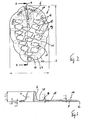
- the figures show a molded article according to the invention designated as a whole by the reference numeral 2 for use in sandals with a toe separation web running essentially perpendicular to the footbed.
- the molded part 2 is intended to be pushed with his apparent from the figures open-edged slot 4 in the direction of the toe separation web in the plane of the footbed of the sandal.
- the open-edge slot 4 is bounded by a sleeve-shaped in the broadest sense section 6 of the molding.
- This sleeve-shaped portion 6, which may also be referred to in the plan view as U-shaped, rises from a projecting flat base portion 8 of the molding 2 upwards.
- the flat base portion 8 lies substantially flat on the footbed of the toe sandal.
- the sleeve-shaped portion 6 rises so this vertically upwards, as can be seen from the figures.
- the projecting flat base portion 8 is continuous and rounded in the sleeve-shaped section 6 on.
- the largest dimension of the molded part 2 defines a longitudinal direction 10 of the molded part. If the molded part 2 is arranged in its intended position on a toe sandal, that is pushed with its open-edged slot 4 on the toe separation web, so this first direction 10 extends substantially in the longitudinal direction of the sandal or the foot. Due to the relatively bulky dimensions of the flat base portion 8, which measures approximately 90 mm in the longitudinal direction 10 in the case illustrated by way of example and approximately 60 mm in the transverse direction, the molded part is not only loaded by the ball of the foot and against the footbed of the sandal pressed, but it also extends slightly behind the actual bale area. Overall, the molding is held very effectively in its intended position due to the very sweeping flat base portion 8 by the burden of the foot.
- the sleeve-shaped section 6 and the edge-open slot 4 bounded by it are inclined to the longitudinal direction 10 in the illustrated case by approximately 10 ° in the counterclockwise direction.
- This is the left version of the molding for the left toe sandals or the left Foot of the user. Due to this inclination, the molded part is ergonomically adapted to the toe gap, and it is thereby largely ensured that the longitudinal direction 10 coincides with the longitudinal direction of the sandal.
- the flat base section 8 which is only about 2 mm thick in the unloaded state, has a contouring 14 of raised areas 16 and recessed areas 18 on its upper side 12 facing the user's foot.
- the raised and the recessed portions 16, 18 are raised or set back by about 0.2 mm from a surface level 20.
- the raised and recessed areas 16, 18 are island-shaped in the example illustrated, and said surface level 20 is formed by the space between the "islands".
- the surface level 20 may also be referred to as the recessed area in the sense of the present invention. This embodiment proves to be particularly advantageous because it exerts an effective, perceived as pleasant massage effect on the user.
- contouring for example, consists of raised areas which rise above a surface level, is possible.
- the surface level surrounding the raised areas then forms the recessed areas. It would also be conceivable that, starting from a surface level (as a raised area), only areas which are set back are provided.
- the flat base portion 8 is tapered toward the peripheral edge 22.
- a discontinuous edge-forming projection prevented from the footbed to the molding out.
- the said structuring 14 is not provided to the peripheral edge 20, but is arranged within a region enclosed by a peripheral edge region 24 mm wide.
Landscapes
- Health & Medical Sciences (AREA)
- Epidemiology (AREA)
- General Health & Medical Sciences (AREA)
- Public Health (AREA)
- Footwear And Its Accessory, Manufacturing Method And Apparatuses (AREA)
Description
- Die Erfindung betriff ein Formteil für die Verwendung bei Sandalen mit einem im Wesentlichen senkrecht zum Fußbett verlaufenden Zehentrennsteg, wobei das Formteil einen hülsenförmigen Abschnitt aufweist und mit diesem um den Zehentrennsteg herum anordenbar ist und so eine verrundete Anlagefläche für die den Zehentrennsteg aufnehmenden Zehen des Benutzers bildet, wobei das Formteil in dem hülsenförmigen Abschnitt einen randoffenen Schlitz aufweist, mit dem das Formteil in der Ebene des Fußbetts auf den Zehentrennsteg aufschiebbar ist bis dieser gegen den hülsenförmigen Abschnitt anliegt und wobei das Formteil einen flachen Basisabschnitt aufweist, der auf das Fußbett der Sandale auflegbar ist und in den hülsenförmigen Abschnitt übergeht.
- Ein derartiges Formteil für Sandalen ist bekannt aus
DE 20 2006 001 669.4 der Anmelderin. - Sandalen der vorstehend genannten Art werden häufig auch als Zehensandalen bezeichnet. Sie bestehen häufig nur aus einem die Sohle und das Fußbett bildenden Teil, an dessen vorderem Bereich ein schlaufenbildendes, eine Einstecköffnung für den Fuß des Benutzers bildendes Mittel vorgesehen ist, welches mit dem Zehentrennsteg verbunden ist und den Fuß des Benutzers oben überfängt. Der Benutzer schlüpft also in diese Sandale, indem er zwischen den Zehen, insbesondere im ersten Zehenzwischenraum den Zehentrennsteg aufnimmt. Das vorgenannte Formteil wird nun mit seinem randoffenen Schlitz in der Ebene des Fußbetts auf den Zehentrennsteg aufgeschoben. Es kann so ein Scheuern des Zehentrennstegs gegen den Zehenzwischenraum, was sich für den Benutzer als unangenehm und schmerzhaft erweisen kann, verhindert werden.
- Der vorliegenden Erfindung liegt die Aufgabe zugrunde, ausgehend von dem bekannten Formteil weitere Verbesserungen hinsichtlich des Tragkomforts und hinsichtlich einer stabilen Anordnung des Formteils an bzw. in der bestimmungsgemäßen Position vorzuschlagen.
- Diese Aufgabe wird bei einem Formteil der genannten Art erfindungsgemäß dadurch gelöst, dass der flache Basisabschnitt in der Draufsicht eine Breite quer zu einer Längsrichtung von wenigstens 40 mm und eine Länge in der Längsrichtung von wenigstens 60 mm aufweist, wobei die Länge wenigstens 20 mm größer ist als die Breite, und dass die Dicke des Basisabschnitts im nicht belasteten Zustand höchstens 2,5 mm beträgt, und dass auf der dem Fuß zugewandten Oberseite des Basisabschnitts eine Konturierung aus erhabenen und zurückgesetzten Bereichen vorgesehen ist, wobei die erhabenen Bereiche gegenüber den zurückgesetzten Bereichen um 0,1 - 1,5 mm vorstehen.
- Dies führt dazu, dass das Formteil durch die Belastung des Fußballens des Benutzers in seiner bestimmungsgemäßen Position fixiert wird, wodurch geringere Relativbewegungen des Formteils gegenüber dem Fußbett der Sandale, gegenüber dem Zehentrennsteg und dem Fuß des Benutzers erreicht werden.
- Des Weiteren wird durch die erfindungsgemäße Konturierung der dem Fuß zugewandten Oberseite des Basisabschnitts, die ja in unmittelbare Berührung mit dem Fuß des Benutzers kommt, eine beim Benutzer als angenehm empfundene zonierte Kontaktierung erreicht, die von Benutzer wie eine Massage empfunden wird.
- Insofern erweist es sich als vorteilhaft, wenn die Breite des Basisabschnitts wenigstens 50 mm, insbesondere wenigstens 55 mm beträgt, und die Länge des Basisabschnitts wenigstens 70 mm, insbesondere wenigstens 80 mm und weiter insbesondere wenigstens 90 mm beträgt.
- In Weiterbildung der Erfindung sind die erhabenen Bereichen gegenüber den zurückgesetzten Bereichen um 0,1 bis 1,0 mm, insbesondere um 0,1 - 0,8 mm, insbesondere um 0,1 - 0,6 mm, insbesondere um 0,1 bis 0,5 mm und weiter insbesondere um 0,15 bis 0,3 mm vorstehend ausgebildet.
- Als besonders angenehm wird es empfunden, wenn die erhabenen Bereiche inselförmig ausgebildet sind. In Weiterbildung dieses Gedankens erweist es sich als vorteilhaft, wenn die Oberseite des Basisabschnitts sowohl gekennzeichnet ist durch inselförmige Bereiche, die gegenüber einem Oberflächenniveau erhaben sind, als auch durch inselförmige Bereiche, die gegenüber einem Oberflächenniveau zurückgesetzt sind. Wenn vorausgehend von Insel gesprochen wird, so ist dies als umschlossener Bereich, der im mathematischen Sinne als zusammenhängend bezeichnet werden kann, gemeint.
- Des Weiteren erweist es sich als vorteilhaft, wenn die erhabenen und zurückgesetzten Bereiche von einem Umfangsrand des Basisabschnitts beabstandet sind, wenn also die Konturierung nur innerhalb eines von einem vorzugsweise umlaufenden Randabschnitt begrenzten Gebiets des Basisabschnitts vorgesehen ist.
- Der vorerwähnte Abstand, also die Breite des genannten Umfangsrandabschnitts beträgt 2 bis 10 mm, insbesondere 4 bis 8 mm.
- Auch erweist es sich als vorteilhaft, wenn der Basisabschnitt zum Umfangsrand hin spitz ausläuft, also die Dicke des Basisabschnitts zum Rand hin geringer wird. Auf diese Weise wird erreicht, dass das Formteil nicht wie eine störende Einlage aufgrund eines unstetigen Verlaufs empfunden wird.
- Als besonders vorteilhafte Weiterbildung von an sich selbständigem Erfindungsgehalt wird eine Ausführungsform betrachtet, die dadurch gekennzeichnet ist, dass die größte Ausdehnung des Formteils eine Längsrichtung des Formteils definiert und dass der randoffene Schlitz in der Draufsicht auf das Formteil zu dieser Längsrichtung geneigt angeordnet ist. Die Neigung beträgt vorteilhafterweise 5 bis 15°, insbesondere 5 bis 10°. Aufgrund einer leichten Neigung des Zehenzwischenraums zur exakten Fußlängsrichtung, die auch der Längsrichtung einer Sandale entspricht, wird eine solche Neigung des randoffenen Schlitzes und somit einer Vorzugsorientierung des hülsenförmigen Abschnitts als angenehm empfunden. Solchenfalls empfiehlt es sich, dass Formteile für die Verwendung am linken Fuß und Formteile für die Verwendung am rechten Fuß mit gegensinniger Neigung angeboten werden.
- Des Weiteren unterstützt diese Neigung aber den im Wesentlichen spielfreien Sitz des Formteils am Zehentrennsteg. Beim Gehen werden nämlich Beschleunigungs- und Verzögerungsbewegungen hauptsächlich in der betrachteten Fuß- oder Sandalenlängsrichtung ausgeführt. Dadurch, dass der randoffene Schlitz, welcher von dem hülsenförmigen Abschnitt begrenzt wird, zu dieser Längsrichtung leicht geneigt ist, wird einem Hin- und Hergleiten in dieser Fuß- oder Sandalenlängsrichtung durch die stützende Wirkung der den schräg angeordneten randoffenen Schlitz begrenzenden Bereiche des Formteils entgegengewirkt.
- Bei dieser Art der besonders bevorzugten Ausbildung des Formteils unterscheidet man zwischen Formteilen für die linke bzw. rechte Sandale mit entsprechender gegensinniger Neigung des randoffenen Schlitzes.
- Vorzugsweise sind Formteile für die linke bzw. rechte Sandale zu einer durch die genannte Längsrichtung definierten Ebene spiegelverkehrt ausgebildet.
- Das Formteil ist vorzugsweise aus einem nachgiebigen Material, insbesondere aus einem elastisch nachgiebigen Material gebildet. Hierfür erweisen sich gelartige Materialien, insbesondere auf PU-Gel-Basis, als besonders vorteilhaft. In gleicher Weise geeignet und vorteilhaft sind Formteile auf Basis von Silikon oder Kautschuk.
- Die Erfindung betrifft auch eine Sandale mit einem im Wesentlichen senkrecht zum Fußbett verlaufenden Zehentrennsteg, eine sogenannte Zehensandale, die gekennzeichnet ist durch ein den Zehentrennsteg umgebendes Formteil der vorausgehend beschriebenen erfindungsgemäßen Art.
- Weitere Merkmale, Einzelheiten und Vorteile der Erfindung ergeben sich aus den beigefügten Patentansprüchen und aus der zeichnerischen Darstellung und nachfolgenden Beschreibung einer bevorzugten Ausführungsform des erfindungsgemäßen Formteils.
- In der Zeichnung zeigt:
- Figur 1
- eine perspektivische Ansicht eines erfindungsgemäßen Formteils für eine Zehensandale;
- Figur 2
- eine Draufsicht auf das Formteil nach
Figur 1 und - Figur 3
- eine Schnittansicht mit Schnittebene A-A in
Figur 2 . - Die Figuren zeigen ein insgesamt mit dem Bezugszeichen 2 bezeichnetes erfindungsgemäßes Formteil für die Verwendung bei Sandalen mit einem im Wesentlichen senkrecht zum Fußbett verlaufenden Zehentrennsteg. Das Formteil 2 wird bestimmungsgemäß mit seinem aus den Figuren ersichtlichen randoffenen Schlitz 4 in Richtung auf den Zehentrennsteg in der Ebene des Fußbetts der Sandale aufgeschoben. Der randoffene Schlitz 4 ist von einem im weitesten Sinne hülsenförmigen Abschnitt 6 des Formteils begrenzt. Dieser hülsenförmige Abschnitt 6, der in der Draufsicht auch als U-förmig bezeichnet werden kann, erhebt sich von einem ausladenden flachen Basisabschnitt 8 des Formteils 2 nach oben. Im Gebrauch liegt der flache Basisabschnitt 8 im Wesentlichen flächenhaft auf dem Fußbett der Zehensandale auf. Der hülsenförmige Abschnitt 6 erhebt sich also hierzu vertikal nach oben, so wie dies aus den Figuren ersichtlich ist. Dabei geht der ausladende flache Basisabschnitt 8 stetig und verrundet in den hülsenförmigen Abschnitt 6 über.
- Die größte Ausdehnung des Formteils 2 definiert eine Längsrichtung 10 des Formteils. Wenn das Formteil 2 in seiner bestimmungsgemäßen Position an einer Zehensandale angeordnet, also mit seinem randoffenen Schlitz 4 auf den Zehentrennsteg aufgeschoben ist, so verläuft diese erste Richtung 10 im Wesentlichen in der Längsrichtung der Sandale bzw. des Fußes. Aufgrund der verhältnismäßig ausladenden Abmessungen des flachen Basisabschnitts 8, der im beispielhaft dargestellten Fall in der Längsrichtung 10 ca. 90 mm und in der Querrichtung hierzu ca. 60 mm misst, wird das Formteil nicht nur vom Ballen des Fußes belastet und gegen das Fußbett der Sandale gedrückt, sondern es erstreckt sich auch noch etwas hinter den eigentlichen Ballenbereich. Insgesamt wird das Formteil aufgrund des sehr ausladenden flachen Basisabschnitts 8 durch die Belastung des Fußes sehr effektiv in seiner bestimmungsgemäßen Position gehalten.
- Man erkennt des Weiteren aus den Figuren, dass der hülsenförmige Abschnitt 6 und der durch ihn begrenzte randoffene Schlitz 4 zu der Längsrichtung 10 im dargestellten Fall um ca. 10° entgegen dem Uhrzeigersinn geneigt ist. Es handelt sich hierbei um die Linksausführung des Formteils für die linke Zehensandale bzw. den linken Fuß des Benutzers. Durch diese Neigung ist das Formteil ergonomisch an den Zehenzwischenraum angepasst, und es wird dabei weitgehend sichergestellt, dass die Längsrichtung 10 mit der Längsrichtung der Sandale übereinstimmt.
- Der im nicht belasteten Zustand nur etwa 2 mm dicke flache Basisabschnitt 8 weist an seiner dem Fuß des Benutzers zugewandten Oberseite 12 eine Konturierung 14 aus erhabenen Bereichen 16 und zurückgesetzten Bereichen 18 auf. Wie in
Figur 3 angedeutet, sind die erhabenen und die zurückgesetzten Bereiche 16, 18 um ca. 0,2 mm gegenüber einem Oberflächenniveau 20 erhaben bzw. zurückgesetzt. Die erhabenen und zurückgesetzten Bereiche 16, 18 sind im beispielhaft dargestellten Fall inselförmig, und das genannte Oberflächenniveau 20 wird durch den Zwischenraum zwischen den "Inseln" gebildet. In Bezug auf die erhabenen Bereiche 16 kann das Oberflächenniveau 20 im Sinne der vorliegenden Erfindung auch als zurückgesetzter Bereich bezeichnet werden. Diese Ausführungsform erweist sich als besonders vorteilhaft, weil sie eine effektive, als angenehm empfundene Massagewirkung auf den Benutzer ausübt. - Es wird jedoch ausdrücklich darauf hingewiesen, dass auch eine andere Konturierung, die beispielsweise aus erhabenen Bereichen besteht, die gegenüber einem Oberflächenniveau emporstehen, möglich ist. Das die erhabenen Bereiche umgebende Oberflächenniveau bildet dann die demgegenüber zurückgesetzten Bereiche. Ebenso wäre es denkbar, dass ausgehend von einem Oberflächenniveau (als erhabener Bereich) nur demgegenüber zurückgesetzte Bereiche vorgesehen sind.
- Bei der dargestellten Ausführungsform läuft der flache Basisabschnitt 8 zum Umfangsrand 22 hin spitz aus. Hierdurch wird ein unstetiger kantenbildender Vorsprung ausgehend vom Fußbett zum Formteil hin verhindert. Des Weiteren erkennt man, dass die genannte Strukturierung 14 nicht bis zum Umfangsrand 20 vorgesehen ist, sondern innerhalb eines von einem einige Millimeter breiten Umfangsrandbereichs 24 umschlossenen Gebiets angeordnet ist.
Claims (13)
- Formteil (2) für die Verwendung bei Sandalen mit einem im wesentlichen senkrecht zum Fußbett verlaufenden Zehentrennsteg, wobei das Formteil (2) einen hülsenförmigen Abschnitt (6) aufweist und mit diesem um den Zehentrennsteg herum anordenbar ist und so eine verrundete Anlagefläche für die den Zehentrennsteg aufnehmenden Zehen des Benutzers bildet, wobei das Formteil in dem hülsenförmigen Abschnitt (6) einen randoffenen Schlitz (4) aufweist, mit dem das Formteil (2) in der Ebene des Fußbetts auf den Zehentrennsteg aufschiebbar ist bis dieser gegen den hülsenförmigen Abschnitt (6) anliegt und wobei das Formteil einen flachen Basisabschnitt (8) aufweist, der auf das Fußbett der Sandale auflegbar ist und in den hülsenförmigen Abschnitt (6) übergeht, dadurch gekennzeichnet, dass der flache Basisabschnitt (8) in der Draufsicht eine Breite quer zu einer Längsrichtung (10) von wenigstens 40 mm und eine Länge in der Längsrichtung (10) von wenigstens 60 mm aufweist, wobei die Länge wenigstens 20 mm größer ist als die Breite, und dass die Dicke des Basisabschnitts (8) im nicht belastetes Zustand höchstens 2,5 mm beträgt, und dass auf der dem Fuß zugewandten Oberseite (12) des Basisabschnitts (8) eine Konturierung (14) aus erhabenen und zurückgesetzten Bereichen (16 bzw. 18) vorgesehen ist, wobei die erhabenen Bereiche (16) gegenüber den zurückgesetzten Bereichen (18) um 0,1 - 1,5 mm vorstehen.
- Formteil nach Anspruch 1, dadurch gekennzeichnet, dass die Breite des Basisabschnitts (8) wenigstens 50 mm, insbesondere wenigstens 55 mm beträgt.
- Formteil nach Anspruch 1 oder 2, dadurch gekennzeichnet, dass die Länge des Basisabschnitts (8) wenigstens 70 mm, insbesondere wenigstens 80 mm und weiter insbesondere wenigstens 90 mm beträgt.
- Formteil nach Anspruch 1, 2 oder 3, dadurch gekennzeichnet, dass die erhabenen Bereiche (16) gegenüber den zurückgesetzten Bereichen (18) um 0,1 bis 1,0 mm, insbesondere um 0,1 - 0,8 mm, insbesondere um 0,1 - 0,6 mm, insbesondere um 0, 1 - 0,5 mm und weiter insbesondere um 0,15 - 0,3 mm vorstehen.
- Formteil nach einem oder mehreren der vorstehenden Ansprüche, dadurch gekennzeichnet, dass die erhabenen Bereiche (16) inselförmig ausgebildet sind.
- Formteil nach Anspruch 5, dadurch gekennzeichnet, gekennzeichnet durch inselförmige Bereiche (16), die gegenüber einem Oberflächenniveau (20) erhaben sind, und durch inselförmige Bereiche (18), die gegenüber einem Oberflächenniveau (20) zurückgesetzt sind.
- Formteil nach einem oder mehreren der vorstehenden Ansprüche dass die erhabenen und zurückgesetzten Bereiche von einem Umfangsrand (22) des Basisabschnitts (8) beabstandet sind.
- Formteil nach Anspruch 7, dadurch gekennzeichnet, dass der Abstand wenigstens 2 - 10 mm, insbesondere 4 - 8 mm beträgt.
- Formteil nach einem oder mehreren der vorstehenden Ansprüche dass der Basisabschnitt (8) zum Umfangsrand (22) hin spitz ausläuft.
- Formteil nach einem oder mehreren der vorstehenden Ansprüche, dadurch gekennzeichnet, dass der hülsenförmige Abschnitt (6) einen Innendurchmesser oder eine Breite des randoffenen Schlitzes von 1 - 4 mm, insbesondere von 2 - 3 mm begrenzt.
- Formteil nach einem oder mehreren der vorstehenden Ansprüche, dadurch gekennzeichnet, dass der hülsenförmige Abschnitt (6) eine Höhe von 10 mm - 20 mm, insbesondere von 12 - 18 mm und weiter insbesondere von 12 - 16 mm aufweist.
- Formteil nach einem oder mehreren der vorstehenden Ansprüche, dadurch gekennzeichnet, dass die größte Ausdehnung des Formteils eine Längsrichtung (10) des Formteils definiert und dass der randoffene Schlitz (4) in der Draufsicht auf das Formteil zu dieser Längsrichtung (10) geneigt angeordnet ist.
- Formteil einem oder mehreren der vorstehenden Ansprüche dass die Neigung 5 - 15°, insbesondere 5 - 10° beträgt.
Priority Applications (5)
| Application Number | Priority Date | Filing Date | Title |
|---|---|---|---|
| DE502006002779T DE502006002779D1 (de) | 2006-10-25 | 2006-10-25 | Formteil für Zehensandale |
| EP06022288A EP1915916B1 (de) | 2006-10-25 | 2006-10-25 | Formteil für Zehensandale |
| ES06022288T ES2319681T3 (es) | 2006-10-25 | 2006-10-25 | Pieza moldeada para una sandalia con separador de dedos. |
| AT06022288T ATE422152T1 (de) | 2006-10-25 | 2006-10-25 | Formteil für zehensandale |
| DK06022288T DK1915916T3 (da) | 2006-10-25 | 2006-10-25 | Formstöbt del til sandaler af klip-klappertypen |
Applications Claiming Priority (1)
| Application Number | Priority Date | Filing Date | Title |
|---|---|---|---|
| EP06022288A EP1915916B1 (de) | 2006-10-25 | 2006-10-25 | Formteil für Zehensandale |
Publications (2)
| Publication Number | Publication Date |
|---|---|
| EP1915916A1 EP1915916A1 (de) | 2008-04-30 |
| EP1915916B1 true EP1915916B1 (de) | 2009-02-04 |
Family
ID=37814150
Family Applications (1)
| Application Number | Title | Priority Date | Filing Date |
|---|---|---|---|
| EP06022288A Not-in-force EP1915916B1 (de) | 2006-10-25 | 2006-10-25 | Formteil für Zehensandale |
Country Status (5)
| Country | Link |
|---|---|
| EP (1) | EP1915916B1 (de) |
| AT (1) | ATE422152T1 (de) |
| DE (1) | DE502006002779D1 (de) |
| DK (1) | DK1915916T3 (de) |
| ES (1) | ES2319681T3 (de) |
Families Citing this family (1)
| Publication number | Priority date | Publication date | Assignee | Title |
|---|---|---|---|---|
| WO2013049877A1 (en) * | 2011-10-07 | 2013-04-11 | 2 Walkon Pty Limited | Open styled footwear and components therefor |
Family Cites Families (3)
| Publication number | Priority date | Publication date | Assignee | Title |
|---|---|---|---|---|
| US20050150132A1 (en) * | 2004-01-14 | 2005-07-14 | Gail Iannacone | Footwear with expanded thermoplastic beads in the footbed |
| GB0411838D0 (en) * | 2004-05-27 | 2004-06-30 | Harrison Matthew J C | Dopie shoe concept |
| DE202006001669U1 (de) | 2005-07-20 | 2006-04-13 | Ingo Pietsch Gmbh & Co. Kg | Formteil für die Verwendung bei Sandalen |
-
2006
- 2006-10-25 ES ES06022288T patent/ES2319681T3/es active Active
- 2006-10-25 AT AT06022288T patent/ATE422152T1/de active
- 2006-10-25 DK DK06022288T patent/DK1915916T3/da active
- 2006-10-25 DE DE502006002779T patent/DE502006002779D1/de active Active
- 2006-10-25 EP EP06022288A patent/EP1915916B1/de not_active Not-in-force
Also Published As
| Publication number | Publication date |
|---|---|
| DK1915916T3 (da) | 2009-04-06 |
| ATE422152T1 (de) | 2009-02-15 |
| ES2319681T3 (es) | 2009-05-11 |
| DE502006002779D1 (de) | 2009-03-19 |
| EP1915916A1 (de) | 2008-04-30 |
Similar Documents
| Publication | Publication Date | Title |
|---|---|---|
| DE102017122278B4 (de) | Sohlenstruktur für schuhe und schuhe mit dieser sohlenstruktur | |
| EP3151694B1 (de) | Schuh, insbesondere laufschuh | |
| DE69802934T2 (de) | Komfortsohle und schuh mit dieser komfortsohle | |
| DE2827172A1 (de) | Fussballschuh oder -stiefel | |
| EP2540181A2 (de) | Sohle für einen Schuh, insbesondere Laufschuh | |
| AT16785U1 (de) | Schuh | |
| WO2006048160A1 (de) | Schuhsohle mit druckmassagefunktion | |
| EP1915916A1 (de) | Formteil für Zehensandale | |
| WO1990008486A1 (de) | Fussbett eines schuhs in form einer separaten fussbetteinlage oder eines mit einem schuh verbundenen fussbettteils | |
| EP1911363A1 (de) | Schuhsohle bzw. Schuhwerk mit Schuhsohle | |
| DE19801301A1 (de) | Schuhinnensohle | |
| DE102013012097B4 (de) | Belastungsadaptierende Struktursohle als kontrollierendes Dämpfungssystem | |
| EP3097810A1 (de) | Einlegesohle | |
| DE202010010359U1 (de) | Schuh | |
| EP3270727A1 (de) | Schuh mit bandscheibenwerkstoff-dämpfungselement | |
| DE29817172U1 (de) | Innensohle für einen Schuh | |
| WO2019219482A1 (de) | Kunstfuss | |
| DE29711812U1 (de) | Matratze | |
| DE202019105745U1 (de) | Fußorthese zur Stabilisierung eines Fußes | |
| EP4335320B1 (de) | Vorrichtung zur applikation von creme auf einen fuss | |
| WO2017089432A1 (de) | Riemenlose zehenstegsandale | |
| EP3020299A1 (de) | Schuh | |
| DE102008063041B4 (de) | Vorrichtung zum Reinigen und/oder Massieren von Füßen | |
| DE3314525A1 (de) | Schuheinlage | |
| CH702899A1 (de) | Schuhsohle und schuh. |
Legal Events
| Date | Code | Title | Description |
|---|---|---|---|
| PUAI | Public reference made under article 153(3) epc to a published international application that has entered the european phase |
Free format text: ORIGINAL CODE: 0009012 |
|
| 17P | Request for examination filed |
Effective date: 20070428 |
|
| AK | Designated contracting states |
Kind code of ref document: A1 Designated state(s): AT BE BG CH CY CZ DE DK EE ES FI FR GB GR HU IE IS IT LI LT LU LV MC NL PL PT RO SE SI SK TR |
|
| AX | Request for extension of the european patent |
Extension state: AL BA HR MK RS |
|
| GRAP | Despatch of communication of intention to grant a patent |
Free format text: ORIGINAL CODE: EPIDOSNIGR1 |
|
| GRAS | Grant fee paid |
Free format text: ORIGINAL CODE: EPIDOSNIGR3 |
|
| GRAA | (expected) grant |
Free format text: ORIGINAL CODE: 0009210 |
|
| AKX | Designation fees paid |
Designated state(s): AT BE BG CH CY CZ DE DK EE ES FI FR GB GR HU IE IS IT LI LT LU LV MC NL PL PT RO SE SI SK TR |
|
| AK | Designated contracting states |
Kind code of ref document: B1 Designated state(s): AT BE BG CH CY CZ DE DK EE ES FI FR GB GR HU IE IS IT LI LT LU LV MC NL PL PT RO SE SI SK TR |
|
| REG | Reference to a national code |
Ref country code: GB Ref legal event code: FG4D Free format text: NOT ENGLISH |
|
| REG | Reference to a national code |
Ref country code: CH Ref legal event code: EP |
|
| REG | Reference to a national code |
Ref country code: IE Ref legal event code: FG4D Free format text: LANGUAGE OF EP DOCUMENT: GERMAN |
|
| REF | Corresponds to: |
Ref document number: 502006002779 Country of ref document: DE Date of ref document: 20090319 Kind code of ref document: P |
|
| REG | Reference to a national code |
Ref country code: DK Ref legal event code: T3 |
|
| REG | Reference to a national code |
Ref country code: ES Ref legal event code: FG2A Ref document number: 2319681 Country of ref document: ES Kind code of ref document: T3 |
|
| PG25 | Lapsed in a contracting state [announced via postgrant information from national office to epo] |
Ref country code: SI Free format text: LAPSE BECAUSE OF FAILURE TO SUBMIT A TRANSLATION OF THE DESCRIPTION OR TO PAY THE FEE WITHIN THE PRESCRIBED TIME-LIMIT Effective date: 20090204 Ref country code: FI Free format text: LAPSE BECAUSE OF FAILURE TO SUBMIT A TRANSLATION OF THE DESCRIPTION OR TO PAY THE FEE WITHIN THE PRESCRIBED TIME-LIMIT Effective date: 20090204 Ref country code: LT Free format text: LAPSE BECAUSE OF FAILURE TO SUBMIT A TRANSLATION OF THE DESCRIPTION OR TO PAY THE FEE WITHIN THE PRESCRIBED TIME-LIMIT Effective date: 20090204 |
|
| PG25 | Lapsed in a contracting state [announced via postgrant information from national office to epo] |
Ref country code: SE Free format text: LAPSE BECAUSE OF FAILURE TO SUBMIT A TRANSLATION OF THE DESCRIPTION OR TO PAY THE FEE WITHIN THE PRESCRIBED TIME-LIMIT Effective date: 20090504 Ref country code: PL Free format text: LAPSE BECAUSE OF FAILURE TO SUBMIT A TRANSLATION OF THE DESCRIPTION OR TO PAY THE FEE WITHIN THE PRESCRIBED TIME-LIMIT Effective date: 20090204 Ref country code: IS Free format text: LAPSE BECAUSE OF FAILURE TO SUBMIT A TRANSLATION OF THE DESCRIPTION OR TO PAY THE FEE WITHIN THE PRESCRIBED TIME-LIMIT Effective date: 20090604 Ref country code: LV Free format text: LAPSE BECAUSE OF FAILURE TO SUBMIT A TRANSLATION OF THE DESCRIPTION OR TO PAY THE FEE WITHIN THE PRESCRIBED TIME-LIMIT Effective date: 20090204 |
|
| REG | Reference to a national code |
Ref country code: IE Ref legal event code: FD4D |
|
| PG25 | Lapsed in a contracting state [announced via postgrant information from national office to epo] |
Ref country code: EE Free format text: LAPSE BECAUSE OF FAILURE TO SUBMIT A TRANSLATION OF THE DESCRIPTION OR TO PAY THE FEE WITHIN THE PRESCRIBED TIME-LIMIT Effective date: 20090204 Ref country code: CZ Free format text: LAPSE BECAUSE OF FAILURE TO SUBMIT A TRANSLATION OF THE DESCRIPTION OR TO PAY THE FEE WITHIN THE PRESCRIBED TIME-LIMIT Effective date: 20090204 Ref country code: IE Free format text: LAPSE BECAUSE OF FAILURE TO SUBMIT A TRANSLATION OF THE DESCRIPTION OR TO PAY THE FEE WITHIN THE PRESCRIBED TIME-LIMIT Effective date: 20090204 Ref country code: PT Free format text: LAPSE BECAUSE OF FAILURE TO SUBMIT A TRANSLATION OF THE DESCRIPTION OR TO PAY THE FEE WITHIN THE PRESCRIBED TIME-LIMIT Effective date: 20090706 |
|
| PG25 | Lapsed in a contracting state [announced via postgrant information from national office to epo] |
Ref country code: RO Free format text: LAPSE BECAUSE OF FAILURE TO SUBMIT A TRANSLATION OF THE DESCRIPTION OR TO PAY THE FEE WITHIN THE PRESCRIBED TIME-LIMIT Effective date: 20090204 Ref country code: SK Free format text: LAPSE BECAUSE OF FAILURE TO SUBMIT A TRANSLATION OF THE DESCRIPTION OR TO PAY THE FEE WITHIN THE PRESCRIBED TIME-LIMIT Effective date: 20090204 |
|
| PLBE | No opposition filed within time limit |
Free format text: ORIGINAL CODE: 0009261 |
|
| STAA | Information on the status of an ep patent application or granted ep patent |
Free format text: STATUS: NO OPPOSITION FILED WITHIN TIME LIMIT |
|
| 26N | No opposition filed |
Effective date: 20091105 |
|
| PG25 | Lapsed in a contracting state [announced via postgrant information from national office to epo] |
Ref country code: BG Free format text: LAPSE BECAUSE OF FAILURE TO SUBMIT A TRANSLATION OF THE DESCRIPTION OR TO PAY THE FEE WITHIN THE PRESCRIBED TIME-LIMIT Effective date: 20090504 |
|
| PG25 | Lapsed in a contracting state [announced via postgrant information from national office to epo] |
Ref country code: MC Free format text: LAPSE BECAUSE OF NON-PAYMENT OF DUE FEES Effective date: 20091031 |
|
| PG25 | Lapsed in a contracting state [announced via postgrant information from national office to epo] |
Ref country code: GR Free format text: LAPSE BECAUSE OF FAILURE TO SUBMIT A TRANSLATION OF THE DESCRIPTION OR TO PAY THE FEE WITHIN THE PRESCRIBED TIME-LIMIT Effective date: 20090505 |
|
| PG25 | Lapsed in a contracting state [announced via postgrant information from national office to epo] |
Ref country code: LU Free format text: LAPSE BECAUSE OF NON-PAYMENT OF DUE FEES Effective date: 20091025 |
|
| REG | Reference to a national code |
Ref country code: CH Ref legal event code: PL |
|
| PG25 | Lapsed in a contracting state [announced via postgrant information from national office to epo] |
Ref country code: HU Free format text: LAPSE BECAUSE OF FAILURE TO SUBMIT A TRANSLATION OF THE DESCRIPTION OR TO PAY THE FEE WITHIN THE PRESCRIBED TIME-LIMIT Effective date: 20090805 |
|
| PG25 | Lapsed in a contracting state [announced via postgrant information from national office to epo] |
Ref country code: CH Free format text: LAPSE BECAUSE OF NON-PAYMENT OF DUE FEES Effective date: 20101031 Ref country code: LI Free format text: LAPSE BECAUSE OF NON-PAYMENT OF DUE FEES Effective date: 20101031 |
|
| PG25 | Lapsed in a contracting state [announced via postgrant information from national office to epo] |
Ref country code: TR Free format text: LAPSE BECAUSE OF FAILURE TO SUBMIT A TRANSLATION OF THE DESCRIPTION OR TO PAY THE FEE WITHIN THE PRESCRIBED TIME-LIMIT Effective date: 20090204 |
|
| PG25 | Lapsed in a contracting state [announced via postgrant information from national office to epo] |
Ref country code: CY Free format text: LAPSE BECAUSE OF FAILURE TO SUBMIT A TRANSLATION OF THE DESCRIPTION OR TO PAY THE FEE WITHIN THE PRESCRIBED TIME-LIMIT Effective date: 20090204 |
|
| REG | Reference to a national code |
Ref country code: DE Ref legal event code: R082 Ref document number: 502006002779 Country of ref document: DE Representative=s name: FIEDLER, OSTERMANN & SCHNEIDER PATENTANWAELTE, DE |
|
| REG | Reference to a national code |
Ref country code: DE Ref legal event code: R082 Ref document number: 502006002779 Country of ref document: DE Representative=s name: FIEDLER, OSTERMANN & SCHNEIDER PATENTANWAELTE, DE |
|
| REG | Reference to a national code |
Ref country code: DE Ref legal event code: R082 Ref document number: 502006002779 Country of ref document: DE Representative=s name: FIEDLER, OSTERMANN & SCHNEIDER PATENTANWAELTE, DE Effective date: 20121114 Ref country code: DE Ref legal event code: R082 Ref document number: 502006002779 Country of ref document: DE Representative=s name: FIEDLER, OSTERMANN & SCHNEIDER PATENTANWAELTE, DE Effective date: 20130712 Ref country code: DE Ref legal event code: R081 Ref document number: 502006002779 Country of ref document: DE Owner name: TACCO FOOTCARE INTERNATIONAL GMBH, DE Free format text: FORMER OWNER: PIETSCH GMBH & CO. KG, 33181 BAD WUENNENBERG, DE Effective date: 20130712 Ref country code: DE Ref legal event code: R082 Ref document number: 502006002779 Country of ref document: DE Representative=s name: PATENTANWAELTE FIEDLER, OSTERMANN & SCHNEIDER, DE Effective date: 20130712 Ref country code: DE Ref legal event code: R082 Ref document number: 502006002779 Country of ref document: DE Representative=s name: PATENTANWAELTE FIEDLER, OSTERMANN & SCHNEIDER, DE Effective date: 20121114 |
|
| REG | Reference to a national code |
Ref country code: NL Ref legal event code: SD Effective date: 20130913 |
|
| REG | Reference to a national code |
Ref country code: GB Ref legal event code: 732E Free format text: REGISTERED BETWEEN 20130919 AND 20130925 |
|
| REG | Reference to a national code |
Ref country code: FR Ref legal event code: TP Owner name: TACCO FOOTCARE INTERNATIONAL GMBH, DE Effective date: 20130926 |
|
| REG | Reference to a national code |
Ref country code: ES Ref legal event code: PC2A Owner name: TACCO FOOTCARE INTERNATIONAL GMBH Effective date: 20131111 |
|
| REG | Reference to a national code |
Ref country code: AT Ref legal event code: PC Ref document number: 422152 Country of ref document: AT Kind code of ref document: T Owner name: TACCO FOOTCARE INTERNATIONAL GMBH, DE Effective date: 20140227 |
|
| PGFP | Annual fee paid to national office [announced via postgrant information from national office to epo] |
Ref country code: FR Payment date: 20141021 Year of fee payment: 9 |
|
| PGFP | Annual fee paid to national office [announced via postgrant information from national office to epo] |
Ref country code: AT Payment date: 20141022 Year of fee payment: 9 Ref country code: NL Payment date: 20141023 Year of fee payment: 9 |
|
| PGFP | Annual fee paid to national office [announced via postgrant information from national office to epo] |
Ref country code: DK Payment date: 20151026 Year of fee payment: 10 |
|
| PGFP | Annual fee paid to national office [announced via postgrant information from national office to epo] |
Ref country code: GB Payment date: 20151026 Year of fee payment: 10 Ref country code: IT Payment date: 20151026 Year of fee payment: 10 |
|
| PGFP | Annual fee paid to national office [announced via postgrant information from national office to epo] |
Ref country code: BE Payment date: 20151022 Year of fee payment: 10 |
|
| REG | Reference to a national code |
Ref country code: AT Ref legal event code: MM01 Ref document number: 422152 Country of ref document: AT Kind code of ref document: T Effective date: 20151025 |
|
| REG | Reference to a national code |
Ref country code: NL Ref legal event code: MM Effective date: 20151101 |
|
| REG | Reference to a national code |
Ref country code: FR Ref legal event code: ST Effective date: 20160630 |
|
| PG25 | Lapsed in a contracting state [announced via postgrant information from national office to epo] |
Ref country code: FR Free format text: LAPSE BECAUSE OF NON-PAYMENT OF DUE FEES Effective date: 20151102 Ref country code: NL Free format text: LAPSE BECAUSE OF NON-PAYMENT OF DUE FEES Effective date: 20151101 Ref country code: AT Free format text: LAPSE BECAUSE OF NON-PAYMENT OF DUE FEES Effective date: 20151025 |
|
| PG25 | Lapsed in a contracting state [announced via postgrant information from national office to epo] |
Ref country code: BE Free format text: LAPSE BECAUSE OF NON-PAYMENT OF DUE FEES Effective date: 20161031 |
|
| PGFP | Annual fee paid to national office [announced via postgrant information from national office to epo] |
Ref country code: ES Payment date: 20161025 Year of fee payment: 11 |
|
| REG | Reference to a national code |
Ref country code: DK Ref legal event code: EBP Effective date: 20161031 |
|
| GBPC | Gb: european patent ceased through non-payment of renewal fee |
Effective date: 20161025 |
|
| PG25 | Lapsed in a contracting state [announced via postgrant information from national office to epo] |
Ref country code: GB Free format text: LAPSE BECAUSE OF NON-PAYMENT OF DUE FEES Effective date: 20161025 |
|
| PG25 | Lapsed in a contracting state [announced via postgrant information from national office to epo] |
Ref country code: IT Free format text: LAPSE BECAUSE OF NON-PAYMENT OF DUE FEES Effective date: 20161025 |
|
| PG25 | Lapsed in a contracting state [announced via postgrant information from national office to epo] |
Ref country code: DK Free format text: LAPSE BECAUSE OF NON-PAYMENT OF DUE FEES Effective date: 20161031 |
|
| REG | Reference to a national code |
Ref country code: BE Ref legal event code: MM Effective date: 20161031 |
|
| REG | Reference to a national code |
Ref country code: ES Ref legal event code: FD2A Effective date: 20181221 |
|
| PG25 | Lapsed in a contracting state [announced via postgrant information from national office to epo] |
Ref country code: ES Free format text: LAPSE BECAUSE OF NON-PAYMENT OF DUE FEES Effective date: 20171026 |
|
| REG | Reference to a national code |
Ref country code: DE Ref legal event code: R082 Ref document number: 502006002779 Country of ref document: DE Representative=s name: MUELLER FOTTNER STEINECKE RECHTSANWAELTE PARTN, DE Ref country code: DE Ref legal event code: R081 Ref document number: 502006002779 Country of ref document: DE Owner name: ALMA F.R.C. SOCIETE PAR ACTIONS SIMPLIFIEE, FR Free format text: FORMER OWNER: TACCO FOOTCARE INTERNATIONAL GMBH, 33689 BIELEFELD, DE |
|
| PGFP | Annual fee paid to national office [announced via postgrant information from national office to epo] |
Ref country code: DE Payment date: 20210622 Year of fee payment: 16 |
|
| REG | Reference to a national code |
Ref country code: DE Ref legal event code: R119 Ref document number: 502006002779 Country of ref document: DE |
|
| P01 | Opt-out of the competence of the unified patent court (upc) registered |
Effective date: 20230522 |
|
| PG25 | Lapsed in a contracting state [announced via postgrant information from national office to epo] |
Ref country code: DE Free format text: LAPSE BECAUSE OF NON-PAYMENT OF DUE FEES Effective date: 20230503 |