EP1915792B1 - Monopolare brennstoffzelle - Google Patents
Monopolare brennstoffzelle Download PDFInfo
- Publication number
- EP1915792B1 EP1915792B1 EP05794581A EP05794581A EP1915792B1 EP 1915792 B1 EP1915792 B1 EP 1915792B1 EP 05794581 A EP05794581 A EP 05794581A EP 05794581 A EP05794581 A EP 05794581A EP 1915792 B1 EP1915792 B1 EP 1915792B1
- Authority
- EP
- European Patent Office
- Prior art keywords
- fuel cell
- plates
- holes
- plate
- modules
- Prior art date
- Legal status (The legal status is an assumption and is not a legal conclusion. Google has not performed a legal analysis and makes no representation as to the accuracy of the status listed.)
- Expired - Lifetime
Links
Images

Classifications
-
- H—ELECTRICITY
- H01—ELECTRIC ELEMENTS
- H01M—PROCESSES OR MEANS, e.g. BATTERIES, FOR THE DIRECT CONVERSION OF CHEMICAL ENERGY INTO ELECTRICAL ENERGY
- H01M8/00—Fuel cells; Manufacture thereof
- H01M8/02—Details
- H01M8/0202—Collectors; Separators, e.g. bipolar separators; Interconnectors
- H01M8/023—Porous and characterised by the material
- H01M8/0232—Metals or alloys
-
- H—ELECTRICITY
- H01—ELECTRIC ELEMENTS
- H01M—PROCESSES OR MEANS, e.g. BATTERIES, FOR THE DIRECT CONVERSION OF CHEMICAL ENERGY INTO ELECTRICAL ENERGY
- H01M8/00—Fuel cells; Manufacture thereof
- H01M8/02—Details
- H01M8/0202—Collectors; Separators, e.g. bipolar separators; Interconnectors
- H01M8/023—Porous and characterised by the material
- H01M8/0241—Composites
- H01M8/0245—Composites in the form of layered or coated products
-
- H—ELECTRICITY
- H01—ELECTRIC ELEMENTS
- H01M—PROCESSES OR MEANS, e.g. BATTERIES, FOR THE DIRECT CONVERSION OF CHEMICAL ENERGY INTO ELECTRICAL ENERGY
- H01M8/00—Fuel cells; Manufacture thereof
- H01M8/02—Details
- H01M8/0202—Collectors; Separators, e.g. bipolar separators; Interconnectors
- H01M8/0247—Collectors; Separators, e.g. bipolar separators; Interconnectors characterised by the form
-
- H—ELECTRICITY
- H01—ELECTRIC ELEMENTS
- H01M—PROCESSES OR MEANS, e.g. BATTERIES, FOR THE DIRECT CONVERSION OF CHEMICAL ENERGY INTO ELECTRICAL ENERGY
- H01M8/00—Fuel cells; Manufacture thereof
- H01M8/02—Details
- H01M8/0202—Collectors; Separators, e.g. bipolar separators; Interconnectors
- H01M8/0258—Collectors; Separators, e.g. bipolar separators; Interconnectors characterised by the configuration of channels, e.g. by the flow field of the reactant or coolant
- H01M8/0263—Collectors; Separators, e.g. bipolar separators; Interconnectors characterised by the configuration of channels, e.g. by the flow field of the reactant or coolant having meandering or serpentine paths
-
- H—ELECTRICITY
- H01—ELECTRIC ELEMENTS
- H01M—PROCESSES OR MEANS, e.g. BATTERIES, FOR THE DIRECT CONVERSION OF CHEMICAL ENERGY INTO ELECTRICAL ENERGY
- H01M8/00—Fuel cells; Manufacture thereof
- H01M8/04—Auxiliary arrangements, e.g. for control of pressure or for circulation of fluids
- H01M8/04082—Arrangements for control of reactant parameters, e.g. pressure or concentration
- H01M8/04089—Arrangements for control of reactant parameters, e.g. pressure or concentration of gaseous reactants
-
- H—ELECTRICITY
- H01—ELECTRIC ELEMENTS
- H01M—PROCESSES OR MEANS, e.g. BATTERIES, FOR THE DIRECT CONVERSION OF CHEMICAL ENERGY INTO ELECTRICAL ENERGY
- H01M8/00—Fuel cells; Manufacture thereof
- H01M8/24—Grouping of fuel cells, e.g. stacking of fuel cells
- H01M8/2457—Grouping of fuel cells, e.g. stacking of fuel cells with both reactants being gaseous or vaporised
-
- H—ELECTRICITY
- H01—ELECTRIC ELEMENTS
- H01M—PROCESSES OR MEANS, e.g. BATTERIES, FOR THE DIRECT CONVERSION OF CHEMICAL ENERGY INTO ELECTRICAL ENERGY
- H01M8/00—Fuel cells; Manufacture thereof
- H01M8/24—Grouping of fuel cells, e.g. stacking of fuel cells
- H01M8/2465—Details of groupings of fuel cells
- H01M8/2483—Details of groupings of fuel cells characterised by internal manifolds
-
- H—ELECTRICITY
- H01—ELECTRIC ELEMENTS
- H01M—PROCESSES OR MEANS, e.g. BATTERIES, FOR THE DIRECT CONVERSION OF CHEMICAL ENERGY INTO ELECTRICAL ENERGY
- H01M8/00—Fuel cells; Manufacture thereof
- H01M8/02—Details
- H01M8/0271—Sealing or supporting means around electrodes, matrices or membranes
- H01M8/0273—Sealing or supporting means around electrodes, matrices or membranes with sealing or supporting means in the form of a frame
-
- H—ELECTRICITY
- H01—ELECTRIC ELEMENTS
- H01M—PROCESSES OR MEANS, e.g. BATTERIES, FOR THE DIRECT CONVERSION OF CHEMICAL ENERGY INTO ELECTRICAL ENERGY
- H01M8/00—Fuel cells; Manufacture thereof
- H01M8/04—Auxiliary arrangements, e.g. for control of pressure or for circulation of fluids
- H01M8/04007—Auxiliary arrangements, e.g. for control of pressure or for circulation of fluids related to heat exchange
- H01M8/04067—Heat exchange or temperature measuring elements, thermal insulation, e.g. heat pipes, heat pumps, fins
-
- H—ELECTRICITY
- H01—ELECTRIC ELEMENTS
- H01M—PROCESSES OR MEANS, e.g. BATTERIES, FOR THE DIRECT CONVERSION OF CHEMICAL ENERGY INTO ELECTRICAL ENERGY
- H01M8/00—Fuel cells; Manufacture thereof
- H01M8/24—Grouping of fuel cells, e.g. stacking of fuel cells
- H01M8/241—Grouping of fuel cells, e.g. stacking of fuel cells with solid or matrix-supported electrolytes
- H01M8/242—Grouping of fuel cells, e.g. stacking of fuel cells with solid or matrix-supported electrolytes comprising framed electrodes or intermediary frame-like gaskets
-
- Y—GENERAL TAGGING OF NEW TECHNOLOGICAL DEVELOPMENTS; GENERAL TAGGING OF CROSS-SECTIONAL TECHNOLOGIES SPANNING OVER SEVERAL SECTIONS OF THE IPC; TECHNICAL SUBJECTS COVERED BY FORMER USPC CROSS-REFERENCE ART COLLECTIONS [XRACs] AND DIGESTS
- Y02—TECHNOLOGIES OR APPLICATIONS FOR MITIGATION OR ADAPTATION AGAINST CLIMATE CHANGE
- Y02E—REDUCTION OF GREENHOUSE GAS [GHG] EMISSIONS, RELATED TO ENERGY GENERATION, TRANSMISSION OR DISTRIBUTION
- Y02E60/00—Enabling technologies; Technologies with a potential or indirect contribution to GHG emissions mitigation
- Y02E60/30—Hydrogen technology
- Y02E60/50—Fuel cells
Definitions
- This patent relates to fuel cells, and particularly concerns the fuel cells using hydrogen plus oxygen or air.
- Fuel cells function on the basis of the chemical interaction between hydrogen and oxygen or air, together with an electrolyte or catalyst, thereby generating electricity, heat and water vapor.
- a fuel cell mainly consists of two electrodes coupled together, with a gas-permeable electrolyte or catalyst membrane inserted between them. A flow of air containing oxygen is delivered to one of the two electrodes (the cathode), while hydrogen is delivered to the other (the anode).
- the electrolyte or catalyst membrane makes the hydrogen atom separate into a proton and an electron, which take a different path with respect to the cathode, i.e. the hydrogen protons flow through the electrolyte or catalyst membrane, while the electrons are collected by the anode, generating a current that can be exploited before the electrons are returned to the cathode.
- Fuel cells are also connected in series physically, so that the flow of reactant gases leaves one cell and enters the next.
- the gas that has moved through one cell without being used up in the chemical reaction can thereby be used in the next cell.
- the efficiency of a fuel cell relies on the efficiency with which each atom of hydrogen is combined with each atom of oxygen.
- these gases are delivered to the membrane in a serpentine flow pattern so as to evenly cover the surface of said membrane, keeping in contact with the electrode.
- a gas diffusion layer is included between the membrane and the electrode so as to further improve the interaction between the single atoms of oxygen and the single atoms of hydrogen.
- the electrodes currently used in the manufacture of fuel cells are made of a substantially flat metal, graphite or graphite-loaded plastic element with serpentine channels for the flow of the gases on both the sides coming into contact with the electrolyte or catalyst membrane.
- each electrode has a serpentine channel on both sides so that it can be coupled with two electrolyte or catalyst membranes, and used in alternating series of electrodes and membranes.
- Electrodes with serpentine channels are currently made out of specifically-shaped metal plates, on the surface(s) of which the serpentine shaping is obtained by milling, electro-discharge machining, melting, or by means of any other suitable procedure.
- Said electrode manufacturing procedure takes a great deal of time both for the shaping of the electrode plates, and to create the serpentine channel, and it involves a great deal of waste material being removed from the plates to make the serpentine channel.
- the resulting electrodes have a considerable thickness and consequently also a considerable weight.
- the electrodes also require further connection elements, both mechanical and for the flow of the fluid.
- the fluid is delivered to one edge of the electrode plate and leaves from another, and elements suitable for connecting them to the fluid circulating manifold, or to the adjacent electrodes, are applied or attached to said edges.
- connection elements demand special processes for their gas-tight manufacture, they involve far from negligible manufacturing costs, and they have to be applied correctly to guarantee the proper operation of the fuel cell.
- WO 03/092105 A relates to a stack of two fuel cells separated by a bipolar plate, each fuel cell comprising two units separated by a MEA, and wherein each unit comprises a monopolar end plate containing a plurality of channels, a non conductive gasket, a gas permeable diffusion medium and a MEA.
- EP A 1 544 931 discloses a monopolar fuel cell stack comprising two current collectors separated by a plate element with serpentine slit.
- the object of the new fuel cell is for each module in the fuel cell to take up less space than in known fuel cells with an equivalent output. Another object of the new fuel cell is to achieve the maximum efficiency of the air-oxygen/hydrogen exchange and a consequently greater efficiency of the system.
- Another object of the new fuel cell is to enable each serpentine gas flow channel to serve two electrolyte or catalyst membranes.
- Another object of the new fuel cell is to need fewer parts for its manufacture.
- Another object of the new fuel cell is to need simple and easily manufactured parts for its construction.
- Another object of the new fuel cell is not to need any costly processes for its manufacture or for the manufacture of its component parts.
- Another object of the new fuel cell is to need a limited number of uncomplicated operations for its assembly.
- Another object of the new fuel cell is to need only a few, straightforward operations and processes for its manufacture.
- Another object of the new fuel cell is to require no specific linking or connection elements between the various single fuel cells coupled together.
- the new fuel cell has layered monopolar modules, each of which includes at least one electrolyte or catalyst membrane, a gas diffusion layer and several plates suitable for being coupled together and complete with holes for enabling the flow of the hydrogen and the air-oxygen.
- the electrolyte or catalyst membrane is a membrane suitable for promoting the separation of the hydrogen atoms into protons and electrons and for enabling the passage of gases, but not of liquids.
- the gas diffusion layer (or GDL) is a porous flat element suitable for promoting the capillary and homogeneous diffusion of the gas.
- Each plate is generically rectangular in shape and, depending on its specific function, is made of a rigid electrically-insulating material, or of a rigid electrically-insulating material coated with a conductive metal layer, or of a metal plate or sheet, or of a flexible sheet coated with a metal layer.
- the central area of the various plates, coming between the previously-mentioned gas flow holes, differs according to the type of plate.
- a first plate called the frame plate, has a central opening of a size sufficient to occupy a large central area coming between said gas flow holes, less a border for separating it from said holes.
- a second plate called the distribution plate, has its central area perforated with tiny holes lying very close to one another. These tiny holes occupy the same area as the central opening in the frame plate.
- a layer of highly conductive metal can be provided on one of the two sides of said distribution plate, extending at least over the area covered by the holes, except for the holes themselves.
- Said highly conductive metal layer extends towards the edges of the plate and is connected to an electric connection terminal, thereby creating an electrical continuity between the various distribution plates, as well as to an electric test terminal so as to enable the operating parameters of each module in the fuel cell to be monitored.
- serpentine plate has a shaped opening in the central area - coinciding with the central opening in the frame plate - that traces a serpentine flow pattern. Said serpentine channel links up with, and places in communication two or more of the gas flow holes.
- Two further types of plate are provided, called the end plate and the blind plate. The end plate only has the gas flow holes, while the blind plate is completely lacking any central openings or gas flow holes.
- the serpentine plates are designed to be larger than the others, or to have appendages on one of their longer sides suitable for serving as a fin to enable heat dispersion.
- Each module in the new fuel cell is symmetrical with respect to the electrolyte or catalyst membrane and includes:
- serpentine plates are used with a symmetrical serpentine channel so that the serpentine channel on each plate links up with a different pair of gas flow holes from those joined together by the serpentine channel on the other serpentine plate.
- the electrolyte or catalyst membrane is slightly larger than the central opening in the frame plate so that it can be held in place by two adjacent frame plates.
- the gas diffusion layer is the same size as the central opening in the frame plate and the same thickness as the frame plate, or slightly thicker.
- the distribution plates are arranged with the metal layer facing towards the catalyst membrane and opposite the adjacent serpentine plate.
- the distribution plate can be made without the highly conductive metal layer, in which case a sheet of flexible electrically-insulating material is used, that is perforated with tiny holes in exactly the same way as the distribution plates coated with a highly conductive metal layer. Said sheet of insulating material is placed between the distribution plate and the catalyst membrane in exactly the same way, with the metal layer facing towards said catalyst membrane.
- each serpentine plate is coupled with two distribution plates and serves two adjacent fuel cell modules.
- the two end and blind plates are placed in the two outermost positions, enclosing and containing all the other plates.
- the electric terminals connecting the various distribution plates are connected together so that each distribution plate is connected not to the distribution plate sharing the same membrane, but to the subsequent distribution plate.
- the distribution plates are connected together alternately, two by two, the plates in even-numbered positions with other plates in even-numbered positions (the 2 nd with the 4 th , the 6 th with the 8 th , and so on) and the distribution plates in odd-numbered positions with distribution plates in odd-numbered positions (the 3 rd with the 5 th , the 7 th with the 9 th , and so on).
- the final, first and last but one, distribution plates are connected to the terminals of the device that uses the electric current generated.
- the above-described plates can be made of a similar material, they may be of limited thickness, in shapes obtained by numerical control cutting or die-cutting processes.
- the new fuel cell as described above, has limited overall dimensions because each combustible and combustion-supporting gas diffusion channel simultaneously serves two membranes.
- the new fuel cell uses elements, i.e. plates, of very limited thickness, so the assembly of the various elements, i.e. the plates, forming a fuel cell module has much smaller overall dimensions than in the fuel cells of known type.
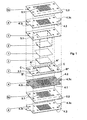
- Each layered module in the new fuel cell includes an electrolyte or catalyst membrane (1), a gas diffusion layer (2), and plates (3, 4, 5, 6, 7).
- the electrolyte or catalyst membrane (1) is a membrane suitable for promoting the separation of the hydrogen atoms into protons and electrons and for enabling the passage of gases, but not of liquids.
- Said electrolyte or catalyst membrane (1) is slightly larger than the central opening (3.1) in the frame plate (3), described below, so that it can be held in place by two frame plates (3) coupled together, and it has a thickness of around a few hundredths of a millimeter.
- the gas diffusion layer (2) is a flat porous element suitable for promoting the even and capillary diffusion of the gas.
- Said gas diffusion layer (2) is preferably composed of a fabric having the necessary characteristics, and is the same size as the central opening (3.1) in the frame plate (3), described below, and is the same thickness, or slightly thicker than said frame plate (3).
- the various plates (3, 4, 5, 6) are generically rectangular in shape, with four holes (A', A", B', B") for enabling the flow of hydrogen (A', A") and air-oxygen (B', B"). Provision can be made for the holes for the air-oxygen flow (B', B") to be slightly larger than the holes for the hydrogen flow (A', A").
- One plate (3) hereinafter called the frame plate (3), has a rectangular central opening (3.1), dimensioned so as to occupy almost all of the area coming between said four gas flow holes (A', A", B', B"), less a rim for separating the opening from said four holes (A', A", B', B").
- Said frame plate (3) is preferably made of vetronite, bakelite or other like material and is around a few tenths of a millimeter thick.
- a second plate called the distribution plate (4), has a central area perforated with tiny holes (4.1) lying very close to one another. Said tiny holes (4.1) cover the same area as the central opening (3.1) in the frame plate (3).
- Said highly conductive metal layer (4.2) extend towards the edges of the plate and is connected to an electric connection terminal (4.3c) and an electric test terminal (4.3t), preferably situated on one or both the shorter sides of the plate (4), to enable the electrical connection between the various distribution plates (4) and the monitoring of the operating parameters of the single fuel cell modules.
- Said distribution plate (4) may be conveniently made of vetronite or bakelite, for instance, coated with platinum or gold, rather like a printed circuit board, and cut, shaped and perforated to obtain the above-described shape.
- said board is rectangular in shape and is perforated like the other plates (3, 5), but it has two tabs on one or two sides that constitute the electric connection terminal (4.3c) and the electric test terminal (4.3t).
- serpentine plate (5) Another plate, called the serpentine plate (5), has a shaped opening that traces a serpentine pattern (5.1) in the central area corresponding to the central opening (3.1) in the frame plate (3).
- Said serpentine-shaped opening (5.1) links up with and places in communication two (A'-A", B'-B") of the four gas flow holes (A', A", B', B”) and, to be more specific, two of the holes that are not diagonally opposite one another (A'-A", B'-B").
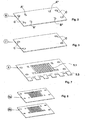
- the shorter side of said serpentine plate (5) is longer than the shorter sides of the other plates (3, 4) so that, when it is assembled with the other plates (3, 4), its edge (5.2) extends beyond the other plates (3, 4). Said edge (5.2) may be toothed or serrated (5.3) ( figure 7 ).
- the serpentine plate (5) is made in two similar versions (5a, 5b), with the serpentine-shaped opening (5.1) connecting one pair of holes (A', A") or the other (B', B").
- Said serpentine plate (5) can conveniently be made, for instance, of metal sheet or other heat-conducting material, about a few tenths of a millimeter thick, and cut, die-cut or obtained by chemical cutting.
- Another plate, called the end plate (6), illustrated in figure 2 only contains the gas flow holes (A', A", B', B") and the holes for centering and assembling the plates (C).
- Another plate called the blind plate (7), illustrated in figure 3 , only has the plate centering and assembly holes (C).
- Each layered module in the new fuel cell is symmetrical with respect to the electrolyte or catalyst membrane (1) ( figure 1 ) and includes :
- the electrolyte or catalyst membrane (1) is contained between and held in place by two frame plates (3), so that the whole of the central opening (3.1) in the frame plate (3) is occupied by said electrolyte or catalyst membrane (1).
- the gas diffusion layer (2) is inserted in said central opening (3.1) in the frame plates (3) so as to fit completely and precisely inside said central opening (3.1) in the frame plate (3) and to cover the corresponding portion of the electrolyte or catalyst membrane (1).
- a serpentine plate (5) is placed over each frame plate (3) and, to be more precise, a serpentine plate (5a) linking the holes for the hydrogen flow (A', A") is placed on one side of the set of plates (3, 4), while a complementary serpentine plate (5b) linking the holes for the air-oxygen flow (B', B") is placed on the other side of the set of plates (3, 4).
- the edges (5.2) of the serpentine plates (5) conveniently all project from the same side of the assembled set of plates (3, 4, 5).
- Said serpentine plates (5) are subsequently coupled, on each side, with another distribution plate (4) and frame plate (3), with a gas diffusion layer (2) and an electrolyte or catalyst membrane (1), repeating the sequence as many times as necessary to obtain the required number of fuel cell modules.
- An end plate (6) and a blind plate (7) are added on the two sides of the fuel cell modules obtained in this way.
- Screws or other suitable mechanical means are inserted through the centering and assembly holes (C) to align, join and press all the plates (3, 4, 5, 6, 7), the electrolyte membranes or catalysts (1) and the gas diffusion layers (2) together.
- the electric terminals (4.3c) for connecting the various distribution plates (4) are connected together so that each distribution plate (4) is connected not to the next distribution plate (4a), but to the next but one distribution plate (4b).
- One embodiment of the invention involves the distribution plate (4) having no highly conductive metal layer (4.2).
- an additional element (8) illustrated in figure 5 , is used, consisting of a sheet of flexible electrically-insulating material (8.1), perforated with tiny holes in the middle (8.2) in exactly the same way as the distribution plate (4), coated with a highly conductive metal layer (8.3).
- Said additional element (8) is preferably made of Kapton or the like and is around a few tenths of a millimeter thick, while the metal layer (8.3) is made of platinum or gold.
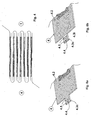
- Said additional element (8) is preferably made double, i.e. it consists of two perforated portions or sheets (8a, 8b) corresponding to the shape of the distribution plate (4), joined together by a band or strip (8c).
- the additional element (8) also has two tabs (8.4a, 8.4b) corresponding to the electric test terminals on the previously-described distribution plate (4) complete with a metal layer (4.2), while the connection terminals are replaced by the connection band or strip (8c).
- the highly conductive metal layer (8.3) is double, and is placed on one side of a sheet (8a), extending over the connection band or strip (8c) and the tab (8.4a), and on the other side of the other sheet (8b), again extending over the connection band or strip (8c) and the tab (8.4b).
- Metal-coated holes are provided and/or created in said connection band or strip (8c) so as to create a contact between the two metal layers (8.3) on the two sides (a, b).
- the additional element (8) constructed in this way, is nonetheless also coupled with two distribution plates (4) without a metal layer (4.2), which serve as mechanical support for the additional element (8).
- Said additional element (8) is bent at the connection band or strip (8c), as shown in figure 6 , and used for two fuel cell modules.
- the new fuel cell constructed in this way, uses the same serpentine plate (5) for two catalyst membranes (1) in two adjacent fuel cell modules, without any plates or separator elements (6, 7) between the various modules, so fewer plates are used than in known fuel cells and, as a result, the new fuel cell takes up less space than the known fuel cells.
- FIG. 8a and 8b Another embodiment of the invention, illustrated in figures 8a and 8b , involves the distribution plate (4) being coated on both sides with a highly conductive metal layer (4.2) extending as far as the connection terminal (4.3c).
- a highly conductive metal layer (4.2) extending as far as the connection terminal (4.3c).
- the distribution plates (4) obtained in this way are coupled with the other plates (3, 5, 6, 7) and the connection between the distribution plates (4) is obtained, for instance, by means of screws or rivets inserted in the holes in the connection terminals (4.3c) and washers inserted between the connection terminals (4.3c).
- the new fuel cell thus obtained uses elements, i.e. plates (3, 4, 5, 6, 7), of a very limited thickness, so the assembly of the various elements, or plates (3, 4, 5, 6, 7), forming a fuel cell module has much smaller overall dimensions than known fuel cells.
- the new fuel cell constructed in this way also has a higher output because the gas circulating in each serpentine plate (5), serving two membranes (1), combines better with the gas, in chemical terms, than in known fuel cells of equivalent overall dimensions.
Landscapes
- Chemical & Material Sciences (AREA)
- Life Sciences & Earth Sciences (AREA)
- Engineering & Computer Science (AREA)
- Manufacturing & Machinery (AREA)
- Sustainable Development (AREA)
- Sustainable Energy (AREA)
- Chemical Kinetics & Catalysis (AREA)
- Electrochemistry (AREA)
- General Chemical & Material Sciences (AREA)
- Composite Materials (AREA)
- Fuel Cell (AREA)
Claims (15)
- Brennstoffzelle mit schichtweise angeordneten Modulen, von denen jedes aus einem Elektrolyten oder einer Katalysatormembran (1) besteht, die an jeder Seite eine Gasdiffusionsschicht (2), eine als Elektrode dienende Verteilerplatte (4, 8) und wenigstens ein Gasverteilungselement (5) aufweisen, welches geeignet ist, das Gas über die Oberfläche der Gasdiffusionsschicht (2) und über die gesamte Membran (1) strömen zu lassen, und wobei jedes Modul mit identischen Modulen verbunden ist, dadurch gekennzeichnet, dass die einzelnen Platten wenigstens zwei Bohrungen (a', a") für den Brenngasstrom aufweisen und wenigstens zwei Bohrungen (b', b") für den Strom des die Verbrennung fördernden Gases haben, und wenn die Platten (3, 4, 5) übereinander geschichtet sind, die Bohrungen (a', a", b', b") Kanalpaare (a'-a", b'-b") für den Zu- und Rückfluss des Brenngases (a', a") und des die Verbrennung fördernden Gases (b', b") bilden, und jedes Brennstoffzellenmodul an jeder Seite des besagten Elektrolyten bzw. der besagten Katalysatormembran (1) Folgendes umschließt:• die besagte Gasdiffusionsschicht (2);• eine Rahmenplatte (3);• die besagte Verteilerplatte (4), die im der mittleren Öffnung (3.1) in der Rahmenplatte (3) entsprechenden Bereich mit kleinen Löchern (4.1) perforiert ist;• das besagte Gasverteilungselement (5), das ein Serpentinenmuster oder Kanal (5.1) aufweist, welches an den beiden Seiten der besagten Serpentinenplatte (5) offen ist und mit der mittleren Öffnung (3.1) in der Rahmenplatte (3) zusammenfällt, und wobei der besagte Serpentinenkanal (5.1) mit wenigstens zweien (a'-a", b'-b") der Gasstrombohrungen (a', a", b', b") verbunden ist und diese miteinander in Kommunikation setzt, wobei das besagte Gasverteilungselement (5) zwei der besagten Verteilerplatten (4) versorgt, und zwar an jeder Seite eines, und dementsprechend auch zwei Gasdiffusionsschichten (2) und zwei Elektrolyten oder Katalysatormembranen (1) in zwei aneinander angrenzenden Modulen;und wobei das besagte Gasverteilungselement (5) in einer Richtung breiter ist als die anderen Platten (3, 4), so dass, es, wenn es mit den anderen Platten (3, 4) gekuppelt ist, mit einer Kante (5.2) aus den anderen Platten (3, 4) hervorsteht, und die hervorstehende Kante (5.2) gezahnt oder gezackt ist (5.3).
- Brennstoffzelle mit schichtweise angeordneten Modulen gemäß Patentanspruch 1, dadurch gekennzeichnet, dass die Rahmenplatte (3) eine rechteckige, mittlere Öffnung (3.1) hat, welche derart bemessen ist, dass sie den Bereich zwischen den besagten Gasstrombohrungen (A', A", B', B") einnimmt, und wobei die besagte mittlere Öffnung (3.1) derart konzipiert ist, dass sie beinahe die gesamte Oberfläche der sich zwischen den beiden Rahmenplatten (3) befindlichen und durch diese in Position gehaltenen Membran (1) zugänglich macht, und derart, dass sie die Gasdiffusionsschicht (2) enthält.
- Brennstoffzelle mit schichtweise angeordneten Modulen gemäß Patentanspruch 2, dadurch gekennzeichnet, dass die Rahmenplatte (3) vorzugsweise aus Vetronit, Bakelit oder ähnlichem Material besteht und ungefähr einige Zehntelmillimeter dick ist.
- Brennstoffzelle mit schichtweise angeordneten Modulen gemäß Patentanspruch 1, dadurch gekennzeichnet, dass die Verteilerplatte (4) im der mittleren Öffnung (3.1) der Rahmenplatte (3) entsprechenden Bereich mit kleinen Löchern (4.1) perforiert ist, und wobei die besagte Verteilerplatte (4) eine hoch leitfähige Metallschicht (4.2) an der zur Membran (1) zeigenden Seite aufweist und sich wenigstens über den gelochten Bereich (4.1) erstreckt, und wobei die besagte, hoch leitfähige Metallschicht (4.2) mit wenigstens einer elektrischen Anschlussklemme (4.3c) verbunden ist.
- Brennstoffzelle mit schichtweise angeordneten Modulen gemäß Patentanspruch 4, dadurch gekennzeichnet, dass die leitfähige Metallschicht (4.2) mit einem elektrischen Prüfklemme (4.3t) verbunden ist.
- Brennstoffzelle mit schichtweise angeordneten Modulen gemäß Patentansprüchen 4, 5, dadurch gekennzeichnet, dass die Kontaktklemmen (4.3c) und/oder Prüfklemmen (4.3t) vorzugsweise an einer oder an beiden kürzeren Seiten der Platte (4) angebracht sind.
- Brennstoffzelle mit schichtweise angeordneten Modulen gemäß Patentansprüchen 4, 5, 6, dadurch gekennzeichnet, dass die besagte Verteilerplatte (4) aus elektrisch isolierendem und mit Platin, Gold oder mit einem anderen, leitfähigen Metall beschichtetem Material besteht.
- Brennstoffzelle mit schichtweise angeordneten Modulen gemäß Patentansprüchen 4, 5, 6, dadurch gekennzeichnet, dass die besagte Verteilerplatte (4) an beiden Seiten der Anschlussklemme (4.3c) mit leitfähigen Metall (4.2) beschichtet ist und wobei besagte Anschlussklemmen wenigstens eine mittlere Bohrung (4.4) und metallbeschichtete Bohrungen (4.5) aufweisen, die den Kontakt zwischen den Beschichtungen (4.2) an den beiden Seiten der Klemmen (4.3c) gewährleisten, und wobei die Verbindung zwischen den einzelnen Verteilerplatten (4) durch zwischen den Anschlussklemmen (4.3c) der Verteilerplatten (4) befindliche und fest zwischen diesen gehaltene Verbindungselemente sichergestellt ist.
- Brennstoffzelle mit schichtweise angeordneten Modulen gemäß Patentanspruch 1, dadurch gekennzeichnet, dass die besagte Verteilerplatte (4) keine hoch leitfähige Metallschicht (4.2) aufweist und dass die besagte Brennstoffzelle ein Zusatzelement (8) umfasst, das aus einem Blatt aus flexiblem, elektrisch isolierendem Material (8.1) besteht, welches in der Mitte ebensolche kleinen Löcher (8.2) aufweist wie die Verteilerplatte (4) und mit einer hoch leitfähigen Metallschicht (8.3) überzogen ist, wobei das besagte Zusatzelement (8) doppelt ausgeführt ist, d.h. aus zwei perforierten Blattabschnitten (8a, 8b) besteht, die der Form der Verteilerplatte (4) entsprechen und durch ein Band oder einen Streifen (8c) mit zwei Laschen (8.4a, 8.4b) miteinander verbunden sind, die sich an einer kürzeren Seite des Zusatzelements (8) und gegenüber dem Band oder einen Streifen (8c) befinden, und wobei die besagte hoch leitfähige Metallschicht (8.3) doppelt ist und sich an einer Seite eines Blatts (8a) befindet, und sich über das Verbindungsband oder den Verbindungsstreifen (8c) und die Lasche (8.4a) erstreckt, und sich an der anderen Seite des anderen Blatts (8b) wiederum über das Verbindungsband oder den Verbindungsstreifen (8c) und die Lasche (8.4b) erstreckt, wobei metallbeschichtete Bohrungen vorhanden sind und/oder in dem besagten Verbindungsband oder -streifen (8c) angebracht werden, um einen Kontakt zwischen den zwei Metallschichten (8.3) an den zwei Seiten (a, b) zu erzeugen, und wobei das besagte Zusatzelement (8) mit zwei Verteilerplatten (4) verbunden ist, wobei das besagte Zusatzelement (8) am Verbindungsband oder -streifen (8c) gebogen ist und für zwei Brennstoffzellenmodule benutzt wird, so dass dieselbe Serpentinenplatte (5) zwei Katalysatormembrane (1) in zwei aneinander angrenzenden Brennstoffzellenmodulen, ohne jegliche Platten oder Trennelemente (6, 7) zwischen den einzelnen Modulen versorgt.
- Brennstoffzelle mit schichtweise angeordneten Modulen gemäß Patentanspruch 1, dadurch gekennzeichnet, dass die besagten, über den Serpentinenkanal (5.1) verbundenen Gasstrombohrungen (A', A", B', B") sich nicht diagonal gegenüberliegen (A'-A", B'-B").
- Brennstoffzelle mit schichtweise angeordneten Modulen gemäß Patentansprüchen 1, 10, dadurch gekennzeichnet, dass die Serpentinenplatte (5) aus einem ungefähr einige Zehntelmillimeter dicken Blatt aus Metall oder einem anderen, wärmeleitenden Metall besteht.
- Brennstoffzelle mit schichtweise angeordneten Modulen gemäß vorstehenden Patentansprüchen, dadurch gekennzeichnet, dass sie eine weitere Abschlussplatte (6) umfasst, die lediglich die Bohrungen (A', A") für den Brenngasstrom und die Bohrungen (B', B") für den Strom des die Verbrennung fördernden Gases enthält, und wobei die besagten Bohrungen (A', A") und (B', B") jeweils auf die besagten Bohrungen (A', A") und (B'-B") der Platten (3, 4, 5) des Brennstoffzellenmoduls ausgerichtet sind.
- Brennstoffzelle mit schichtweise angeordneten Modulen gemäß vorstehenden Patentansprüchen, dadurch gekennzeichnet, dass sie eine weitere Blindplatte (7) ohne die Gasstrombohrungen (A', A", B', B") umfasst.
- Brennstoffzelle mit schichtweise angeordneten Modulen gemäß vorstehenden Patentansprüchen, dadurch gekennzeichnet, dass die Platten (3, 4, 5, 6, 7) an den Ecken Bohrungen (C) aufweisen, die das Zentrieren der einzelnen Platten (3, 4, 5, 6, 7) sowie den Einsatz mechanischer Mittel, die dafür sorgen, dass die besagten Platten (3, 4, 5, 6, 7) perfekt aneinander anliegen, ermöglichen und erleichtern.
- Brennstoffzelle mit schichtweise angeordneten Modulen gemäß vorstehenden Patentansprüchen, dadurch gekennzeichnet, dass sie einen Film mit einem Loch in der Mitte umfasst, der als Dichtung zwischen jedem Paar der besagten Platten (3, 4, 5, 6, 7) dient.
Applications Claiming Priority (1)
| Application Number | Priority Date | Filing Date | Title |
|---|---|---|---|
| PCT/IT2005/000493 WO2007020664A1 (en) | 2005-08-16 | 2005-08-16 | Monopolar fuel cell |
Publications (2)
| Publication Number | Publication Date |
|---|---|
| EP1915792A1 EP1915792A1 (de) | 2008-04-30 |
| EP1915792B1 true EP1915792B1 (de) | 2010-06-23 |
Family
ID=36128562
Family Applications (1)
| Application Number | Title | Priority Date | Filing Date |
|---|---|---|---|
| EP05794581A Expired - Lifetime EP1915792B1 (de) | 2005-08-16 | 2005-08-16 | Monopolare brennstoffzelle |
Country Status (4)
| Country | Link |
|---|---|
| EP (1) | EP1915792B1 (de) |
| AT (1) | ATE472183T1 (de) |
| DE (1) | DE602005021993D1 (de) |
| WO (1) | WO2007020664A1 (de) |
Families Citing this family (2)
| Publication number | Priority date | Publication date | Assignee | Title |
|---|---|---|---|---|
| DE102010023021A1 (de) * | 2010-06-08 | 2011-12-08 | Enymotion Gmbh | Brennstoffzelle mit einem Stack aus mehreren Bipolarplatten |
| JP6392688B2 (ja) * | 2015-03-09 | 2018-09-19 | 日本特殊陶業株式会社 | 燃料電池スタック |
Family Cites Families (3)
| Publication number | Priority date | Publication date | Assignee | Title |
|---|---|---|---|---|
| US7081316B2 (en) * | 2002-04-30 | 2006-07-25 | General Motors Corporation | Bipolar plate assembly having transverse legs |
| DK1394877T3 (da) * | 2002-07-31 | 2013-01-14 | Sfc Energy Ag | Pladeelementer til brændselscellesstakke |
| EP1544931B1 (de) * | 2003-12-17 | 2010-03-17 | SFC Smart Fuel AG | Stromabnehmer für Brennstoffzellenstacks |
-
2005
- 2005-08-16 EP EP05794581A patent/EP1915792B1/de not_active Expired - Lifetime
- 2005-08-16 AT AT05794581T patent/ATE472183T1/de not_active IP Right Cessation
- 2005-08-16 DE DE602005021993T patent/DE602005021993D1/de not_active Expired - Lifetime
- 2005-08-16 WO PCT/IT2005/000493 patent/WO2007020664A1/en not_active Ceased
Also Published As
| Publication number | Publication date |
|---|---|
| ATE472183T1 (de) | 2010-07-15 |
| DE602005021993D1 (de) | 2010-08-05 |
| WO2007020664A1 (en) | 2007-02-22 |
| EP1915792A1 (de) | 2008-04-30 |
Similar Documents
| Publication | Publication Date | Title |
|---|---|---|
| EP1107339B1 (de) | Strömungskanäle in Stromabnehmerplatten von Brennstoffzellen | |
| RU2630896C2 (ru) | Газораспределительный элемент для топливного элемента | |
| CA2551609C (en) | Solid oxide fuel cell and fuel cell stack having mechanism for applying load in stacking direction | |
| US20040247987A1 (en) | Fuel cell | |
| JP2009004251A (ja) | 燃料電池セルスタック、燃料電池セルスタックユニット及び燃料電池 | |
| CN214336753U (zh) | 一种燃料电池及电池组 | |
| CN107408711A (zh) | 燃料电池堆 | |
| US5269902A (en) | Ion-conducting module having axially-arranged solid state electrolyte elements | |
| US7763393B2 (en) | Fuel cell having electrode channel member with comb-teeth shape | |
| JP4922556B2 (ja) | 燃料電池構造 | |
| US20080199740A1 (en) | Interconnect of a planar fuel cell array | |
| US7794891B2 (en) | Fuel cell with interweaving current collector and membrane electrode assembly | |
| CN115149023B (zh) | 一种固体氧化物燃料电池用连接体及电池单元 | |
| WO2010126506A1 (en) | High-volume-manufacture fuel cell arrangement and method for production thereof | |
| JP5401438B2 (ja) | 平板型固体電解質燃料電池 | |
| US20090197136A1 (en) | High-Volume-Manufacture Fuel Cell Arrangement and Method for Production Thereof | |
| JPH04298964A (ja) | 固体電解質型燃料電池及びその製造方法 | |
| EP1915792A1 (de) | Monopolare brennstoffzelle | |
| CN102255090B (zh) | 具有可变特性的端部电池热屏障 | |
| JP5257856B2 (ja) | 燃料電池セルスタックユニット | |
| US20240097152A1 (en) | Electrochemical device | |
| JP5257858B2 (ja) | 燃料電池セルスタックユニット | |
| JP5257857B2 (ja) | 燃料電池セルスタックユニット | |
| JP5257855B2 (ja) | 燃料電池セルスタックユニット | |
| JP2025076541A (ja) | 電解モジュール及び電解装置 |
Legal Events
| Date | Code | Title | Description |
|---|---|---|---|
| PUAI | Public reference made under article 153(3) epc to a published international application that has entered the european phase |
Free format text: ORIGINAL CODE: 0009012 |
|
| 17P | Request for examination filed |
Effective date: 20080206 |
|
| AK | Designated contracting states |
Kind code of ref document: A1 Designated state(s): AT BE BG CH CY CZ DE DK EE ES FI FR GB GR HU IE IS IT LI LT LU LV MC NL PL PT RO SE SI SK TR |
|
| 17Q | First examination report despatched |
Effective date: 20080709 |
|
| GRAJ | Information related to disapproval of communication of intention to grant by the applicant or resumption of examination proceedings by the epo deleted |
Free format text: ORIGINAL CODE: EPIDOSDIGR1 |
|
| GRAP | Despatch of communication of intention to grant a patent |
Free format text: ORIGINAL CODE: EPIDOSNIGR1 |
|
| GRAP | Despatch of communication of intention to grant a patent |
Free format text: ORIGINAL CODE: EPIDOSNIGR1 |
|
| DAX | Request for extension of the european patent (deleted) | ||
| GRAS | Grant fee paid |
Free format text: ORIGINAL CODE: EPIDOSNIGR3 |
|
| GRAA | (expected) grant |
Free format text: ORIGINAL CODE: 0009210 |
|
| AK | Designated contracting states |
Kind code of ref document: B1 Designated state(s): AT BE BG CH CY CZ DE DK EE ES FI FR GB GR HU IE IS IT LI LT LU LV MC NL PL PT RO SE SI SK TR |
|
| REG | Reference to a national code |
Ref country code: CH Ref legal event code: EP |
|
| REG | Reference to a national code |
Ref country code: IE Ref legal event code: FG4D |
|
| REF | Corresponds to: |
Ref document number: 602005021993 Country of ref document: DE Date of ref document: 20100805 Kind code of ref document: P |
|
| REG | Reference to a national code |
Ref country code: NL Ref legal event code: VDEP Effective date: 20100623 |
|
| PG25 | Lapsed in a contracting state [announced via postgrant information from national office to epo] |
Ref country code: LT Free format text: LAPSE BECAUSE OF FAILURE TO SUBMIT A TRANSLATION OF THE DESCRIPTION OR TO PAY THE FEE WITHIN THE PRESCRIBED TIME-LIMIT Effective date: 20100623 Ref country code: SE Free format text: LAPSE BECAUSE OF FAILURE TO SUBMIT A TRANSLATION OF THE DESCRIPTION OR TO PAY THE FEE WITHIN THE PRESCRIBED TIME-LIMIT Effective date: 20100623 |
|
| LTIE | Lt: invalidation of european patent or patent extension |
Effective date: 20100623 |
|
| PG25 | Lapsed in a contracting state [announced via postgrant information from national office to epo] |
Ref country code: SI Free format text: LAPSE BECAUSE OF FAILURE TO SUBMIT A TRANSLATION OF THE DESCRIPTION OR TO PAY THE FEE WITHIN THE PRESCRIBED TIME-LIMIT Effective date: 20100623 Ref country code: LV Free format text: LAPSE BECAUSE OF FAILURE TO SUBMIT A TRANSLATION OF THE DESCRIPTION OR TO PAY THE FEE WITHIN THE PRESCRIBED TIME-LIMIT Effective date: 20100623 Ref country code: FI Free format text: LAPSE BECAUSE OF FAILURE TO SUBMIT A TRANSLATION OF THE DESCRIPTION OR TO PAY THE FEE WITHIN THE PRESCRIBED TIME-LIMIT Effective date: 20100623 Ref country code: AT Free format text: LAPSE BECAUSE OF FAILURE TO SUBMIT A TRANSLATION OF THE DESCRIPTION OR TO PAY THE FEE WITHIN THE PRESCRIBED TIME-LIMIT Effective date: 20100623 |
|
| PG25 | Lapsed in a contracting state [announced via postgrant information from national office to epo] |
Ref country code: GR Free format text: LAPSE BECAUSE OF FAILURE TO SUBMIT A TRANSLATION OF THE DESCRIPTION OR TO PAY THE FEE WITHIN THE PRESCRIBED TIME-LIMIT Effective date: 20100924 Ref country code: PL Free format text: LAPSE BECAUSE OF FAILURE TO SUBMIT A TRANSLATION OF THE DESCRIPTION OR TO PAY THE FEE WITHIN THE PRESCRIBED TIME-LIMIT Effective date: 20100623 |
|
| PG25 | Lapsed in a contracting state [announced via postgrant information from national office to epo] |
Ref country code: NL Free format text: LAPSE BECAUSE OF FAILURE TO SUBMIT A TRANSLATION OF THE DESCRIPTION OR TO PAY THE FEE WITHIN THE PRESCRIBED TIME-LIMIT Effective date: 20100623 Ref country code: EE Free format text: LAPSE BECAUSE OF FAILURE TO SUBMIT A TRANSLATION OF THE DESCRIPTION OR TO PAY THE FEE WITHIN THE PRESCRIBED TIME-LIMIT Effective date: 20100623 |
|
| PG25 | Lapsed in a contracting state [announced via postgrant information from national office to epo] |
Ref country code: IS Free format text: LAPSE BECAUSE OF FAILURE TO SUBMIT A TRANSLATION OF THE DESCRIPTION OR TO PAY THE FEE WITHIN THE PRESCRIBED TIME-LIMIT Effective date: 20101023 Ref country code: CY Free format text: LAPSE BECAUSE OF FAILURE TO SUBMIT A TRANSLATION OF THE DESCRIPTION OR TO PAY THE FEE WITHIN THE PRESCRIBED TIME-LIMIT Effective date: 20100623 Ref country code: BE Free format text: LAPSE BECAUSE OF FAILURE TO SUBMIT A TRANSLATION OF THE DESCRIPTION OR TO PAY THE FEE WITHIN THE PRESCRIBED TIME-LIMIT Effective date: 20100623 Ref country code: CZ Free format text: LAPSE BECAUSE OF FAILURE TO SUBMIT A TRANSLATION OF THE DESCRIPTION OR TO PAY THE FEE WITHIN THE PRESCRIBED TIME-LIMIT Effective date: 20100623 Ref country code: SK Free format text: LAPSE BECAUSE OF FAILURE TO SUBMIT A TRANSLATION OF THE DESCRIPTION OR TO PAY THE FEE WITHIN THE PRESCRIBED TIME-LIMIT Effective date: 20100623 Ref country code: RO Free format text: LAPSE BECAUSE OF FAILURE TO SUBMIT A TRANSLATION OF THE DESCRIPTION OR TO PAY THE FEE WITHIN THE PRESCRIBED TIME-LIMIT Effective date: 20100623 Ref country code: PT Free format text: LAPSE BECAUSE OF FAILURE TO SUBMIT A TRANSLATION OF THE DESCRIPTION OR TO PAY THE FEE WITHIN THE PRESCRIBED TIME-LIMIT Effective date: 20101025 |
|
| PG25 | Lapsed in a contracting state [announced via postgrant information from national office to epo] |
Ref country code: MC Free format text: LAPSE BECAUSE OF NON-PAYMENT OF DUE FEES Effective date: 20100831 |
|
| REG | Reference to a national code |
Ref country code: CH Ref legal event code: PL |
|
| PG25 | Lapsed in a contracting state [announced via postgrant information from national office to epo] |
Ref country code: LI Free format text: LAPSE BECAUSE OF NON-PAYMENT OF DUE FEES Effective date: 20100831 Ref country code: CH Free format text: LAPSE BECAUSE OF NON-PAYMENT OF DUE FEES Effective date: 20100831 Ref country code: DK Free format text: LAPSE BECAUSE OF FAILURE TO SUBMIT A TRANSLATION OF THE DESCRIPTION OR TO PAY THE FEE WITHIN THE PRESCRIBED TIME-LIMIT Effective date: 20100623 |
|
| PLBE | No opposition filed within time limit |
Free format text: ORIGINAL CODE: 0009261 |
|
| STAA | Information on the status of an ep patent application or granted ep patent |
Free format text: STATUS: NO OPPOSITION FILED WITHIN TIME LIMIT |
|
| 26N | No opposition filed |
Effective date: 20110324 |
|
| REG | Reference to a national code |
Ref country code: DE Ref legal event code: R097 Ref document number: 602005021993 Country of ref document: DE Effective date: 20110323 |
|
| PG25 | Lapsed in a contracting state [announced via postgrant information from national office to epo] |
Ref country code: IE Free format text: LAPSE BECAUSE OF NON-PAYMENT OF DUE FEES Effective date: 20100816 |
|
| PGFP | Annual fee paid to national office [announced via postgrant information from national office to epo] |
Ref country code: DE Payment date: 20110830 Year of fee payment: 7 Ref country code: FR Payment date: 20110830 Year of fee payment: 7 Ref country code: GB Payment date: 20110825 Year of fee payment: 7 |
|
| PGFP | Annual fee paid to national office [announced via postgrant information from national office to epo] |
Ref country code: IT Payment date: 20110729 Year of fee payment: 7 |
|
| PG25 | Lapsed in a contracting state [announced via postgrant information from national office to epo] |
Ref country code: BG Free format text: LAPSE BECAUSE OF FAILURE TO SUBMIT A TRANSLATION OF THE DESCRIPTION OR TO PAY THE FEE WITHIN THE PRESCRIBED TIME-LIMIT Effective date: 20100623 Ref country code: LU Free format text: LAPSE BECAUSE OF NON-PAYMENT OF DUE FEES Effective date: 20100816 Ref country code: HU Free format text: LAPSE BECAUSE OF FAILURE TO SUBMIT A TRANSLATION OF THE DESCRIPTION OR TO PAY THE FEE WITHIN THE PRESCRIBED TIME-LIMIT Effective date: 20101224 |
|
| PG25 | Lapsed in a contracting state [announced via postgrant information from national office to epo] |
Ref country code: TR Free format text: LAPSE BECAUSE OF FAILURE TO SUBMIT A TRANSLATION OF THE DESCRIPTION OR TO PAY THE FEE WITHIN THE PRESCRIBED TIME-LIMIT Effective date: 20100623 |
|
| GBPC | Gb: european patent ceased through non-payment of renewal fee |
Effective date: 20120816 |
|
| REG | Reference to a national code |
Ref country code: FR Ref legal event code: ST Effective date: 20130430 |
|
| PG25 | Lapsed in a contracting state [announced via postgrant information from national office to epo] |
Ref country code: IT Free format text: LAPSE BECAUSE OF NON-PAYMENT OF DUE FEES Effective date: 20120816 |
|
| PG25 | Lapsed in a contracting state [announced via postgrant information from national office to epo] |
Ref country code: DE Free format text: LAPSE BECAUSE OF NON-PAYMENT OF DUE FEES Effective date: 20130301 Ref country code: GB Free format text: LAPSE BECAUSE OF NON-PAYMENT OF DUE FEES Effective date: 20120816 |
|
| PG25 | Lapsed in a contracting state [announced via postgrant information from national office to epo] |
Ref country code: FR Free format text: LAPSE BECAUSE OF NON-PAYMENT OF DUE FEES Effective date: 20120831 |
|
| REG | Reference to a national code |
Ref country code: DE Ref legal event code: R119 Ref document number: 602005021993 Country of ref document: DE Effective date: 20130301 |
|
| PG25 | Lapsed in a contracting state [announced via postgrant information from national office to epo] |
Ref country code: BG Free format text: LAPSE BECAUSE OF FAILURE TO SUBMIT A TRANSLATION OF THE DESCRIPTION OR TO PAY THE FEE WITHIN THE PRESCRIBED TIME-LIMIT Effective date: 20100923 |
|
| PG25 | Lapsed in a contracting state [announced via postgrant information from national office to epo] |
Ref country code: ES Free format text: LAPSE BECAUSE OF FAILURE TO SUBMIT A TRANSLATION OF THE DESCRIPTION OR TO PAY THE FEE WITHIN THE PRESCRIBED TIME-LIMIT Effective date: 20101004 |