EP1915047A2 - DC-AC-Wandler Gehäuse für harsche Umweltbedingungen - Google Patents
DC-AC-Wandler Gehäuse für harsche Umweltbedingungen Download PDFInfo
- Publication number
- EP1915047A2 EP1915047A2 EP07118630A EP07118630A EP1915047A2 EP 1915047 A2 EP1915047 A2 EP 1915047A2 EP 07118630 A EP07118630 A EP 07118630A EP 07118630 A EP07118630 A EP 07118630A EP 1915047 A2 EP1915047 A2 EP 1915047A2
- Authority
- EP
- European Patent Office
- Prior art keywords
- assembly
- housing
- heat sink
- channel
- static inverter
- Prior art date
- Legal status (The legal status is an assumption and is not a legal conclusion. Google has not performed a legal analysis and makes no representation as to the accuracy of the status listed.)
- Withdrawn
Links
Images


Classifications
-
- H—ELECTRICITY
- H05—ELECTRIC TECHNIQUES NOT OTHERWISE PROVIDED FOR
- H05K—PRINTED CIRCUITS; CASINGS OR CONSTRUCTIONAL DETAILS OF ELECTRIC APPARATUS; MANUFACTURE OF ASSEMBLAGES OF ELECTRICAL COMPONENTS
- H05K7/00—Constructional details common to different types of electric apparatus
- H05K7/20—Modifications to facilitate cooling, ventilating, or heating
- H05K7/2089—Modifications to facilitate cooling, ventilating, or heating for power electronics, e.g. for inverters for controlling motor
- H05K7/20909—Forced ventilation, e.g. on heat dissipaters coupled to components
- H05K7/20918—Forced ventilation, e.g. on heat dissipaters coupled to components the components being isolated from air flow, e.g. hollow heat sinks, wind tunnels or funnels
Definitions
- the present disclosure relates to inverters and, more particularly, to static inverters for aircraft, marine and vehicle applications.
- Static inverters are used on board aircraft, marine vessels and motorized vehicles to convert direct current voltage, typically 12 or 28 volts DC, generated by the associated aircraft, vessel or vehicle, to alternating current suitable for operating accessories and peripheral equipment that may be on board.
- a static inverter must be environmentally hardened; that is, the inverter must be enclosed within a case that is resistant to dust, electromagnetic frequencies (EMF), salt spray, oils and lubricants, and cleaning fluids and solutions.
- EMF electromagnetic frequencies
- salt spray oils and lubricants
- cleaning fluids and solutions typically also be configured to dissipate the heat that is generated during operation of the inverter. It is also desirable to maximize the power generation by the inverter within a minimal space.
- the disclosed static inverter with hardened environmental housing may include a housing, a heat sink connected to the housing to define an enclosed three-dimensional volume, the heat sink including at least one channel extending therethrough, the channel including a plurality of cooling fins, a cooling fan positioned relative to the channel to encourage a fluid flow through the channel, and static inverter electronics positioned in the enclosed three-dimensional volume, wherein heat generated by the static inverter electronics is dissipated by the fluid flow through the heat sink.
- the disclosed static inverter with hardened environmental housing may include a housing, a heat sink connected to the housing to define an enclosed three-dimensional volume, the heat sink including a plurality of generally elongated channels extending therethrough, each channel of the plurality of channels including a plurality of cooling fins, an inlet and an outlet, the inlet and the outlet being exposed to ambient atmosphere, at least one cooling fan positioned generally adjacent to at least one of the inlet and the outlet to encourage a fluid flow through the plurality of channels, static inverter electronics positioned in the enclosed three-dimensional volume, wherein heat generated by the static inverter electronics is dissipated to the ambient atmosphere by the fluid flow through the heat sink, and a connector disposed on the housing and in communication with the static inverter electronics.
- Fig. 1 is a front perspective view of the disclosed static inverter with hardened environmental housing
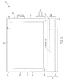
- Fig. 2 is a rear elevation of the static inverter of Fig. 1;
- Fig. 3 is a side elevation of the static inverted of Fig. 1;
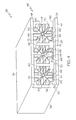
- Fig. 4 is a front perspective view of the heat sink of the static inverter of Fig. 1;
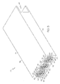
- Fig. 5 is a rear perspective view of the heat sink of Fig. 4.
- the present disclosure is directed to a lightweight, environmentally hardened static inverter that provides relatively high power density in a relatively small volume. These benefits are achieved through the use of an environmentally hardened enclosure that includes an efficient heat sink.
- one aspect of the disclosed static inverter with hardened environmental housing may include a housing 12 having longitudinal side walls 14, 16 and a top wall 18.
- the housing 12 may also include front and rear end walls 20, 22, respectively.
- the side walls 14, 16 and the top wall 18 may be unitary in construction and may include flanges 19 (see also Fig. 2) that provide mounting surfaces for the end walls 20, 22.
- the end walls 20, 22 may be attached to the side walls 14, 16 and top wall 18 by engaging the flanges 19 with a plurality of fasteners 24, such as screws or the like.
- O-rings, gaskets and the like may be positioned between the side and top walls 14, 16, 18 and the end walls 20, 22 to provide a seal from the environment and reduce or eliminate the passage of contaminants, such as dust and rain, across the housing 12.
- the housing 12 may be formed from a durable and generally rigid materials, such as metal or hard plastic. Those skilled in the art will appreciate that the selection of material for the housing 12 may be dictated by the intended use of the static inverter assembly 10. For example, naval applications may require a housing 12 capable of withstanding salt water exposure and large temperature fluctuations and, therefore, may be formed from an appropriate composite polymeric material.
- the bottom portion A of the static inverter assembly 10 may include a heat sink 26 that covers and encloses the underside of the housing 12.
- the heat sink 26 may be made from a cast or extruded metal, such as aluminum alloy.
- the heat sink 26 may be made by casting aluminum 356/T6 alloy or extruding 6063 aluminum alloy.
- side walls 14, 16 are shown as extending to cover the heat sink 26 (see Figs. 1-3), those skilled in the art will appreciate that the side walls, 14, 16 could be shorter and could be attached to a corresponding flange (not shown) extending upwardly from the top surface 34 of the heat sink 26.
- the heat sink 26 may include three interior channels 28, 30, 32 extending therethrough and having an inlet (Fig. 4) and an outlet (Fig. 5).
- the front end wall 20 of the housing 12 may include a cutout or cutouts 75 sized and shaped to align with the channels 28, 30, 32 of the heat sink 26 and expose the channels to the environment.
- the cutouts 75 may be protected by grates 82 connected to the housing 12 and positioned over the cutouts.
- the rear end wall 22 of the housing 12 may include a cutout portion 76 sized and shaped to align with the channels 28, 30, 32 of the heat sink 26 and expose the channels to the environment.
- the cutout portion 76 may be protected by a grate (not shown) similar to grates 82.
- heat sink 26 may be provided with a greater or fewer number of channels.
- the heat sink 26 may include a top wall 34, two side walls 36, 38, a bottom wall 40 and two end walls 42, 44.
- the rear end wall 42 of the heat sink 26 may be sized and shaped to engage the end wall 22 of the housing 12 (see Fig. 1).
- the front end wall 44 of the heat sink 26 may include a notch 46 sized and shaped to receive one or more cooling fans 47 (Fig. 3) therein.
- An example of an appropriate cooling fan 47 includes a Model MD4028 series high performance DC fan manufactured by Mechatronics Corp. of Preston, Washington.
- the notch 46 may extend the width of the heat sink 26.
- the outermost edges 48, 50 of the end 44 may be shaped to engage the end wall 20 of the housing 12 (see Fig. 3).
- each channel 28, 30, 32 may be substantially the same in construction or, alternatively, one or more of the channels 28, 30, 32 may have a different geometry than the other channels.
- each channel 28, 30, 32 may include side walls 52, 54, a top wall 56 and a bottom wall 58.
- the walls 52, 54, 56, 58 may be offset in a cruciform pattern such that a generally "I-beam" structure 60 is formed between adjacent channels.
- the walls 52, 54, 56, 58 may include inwardly extending cooling fins 62 that may extend the entire length of the channel 28.
- Connective cooling fins 64, 66, 68, 70 may be provided that extend across the entire width of the channel 28 to provide structural support.
- various numbers, arrangements and geometries of cooling fins may be used without departing from the scope of the present disclosure.
- the housing 12 and the heat sink 26 connected thereto may define a three-dimensional volume in which static inverter electronics 29 (Fig. 3) may be contained.
- the end panel 20 may include a plug connector 78 and other connectors 80 that allow a user to interface with the static inverter electronics 29 (Fig. 3).
- An example of an appropriate connector 80 is a Model 2201 terminal feed-through connector manufactured by Blue Sea Systems, Inc. of Bellingham, Washington.
- the I-beam structures 60 (Figs. 2, 4 and 5) conduct heat from the top surface 34 of the heat sink 26, which receives heat from the static inverter electronics 29 within the housing 12 (see Fig. 3), such that the heat is radiated from the cooling ribs 62, 64, 66, 68, 70 and transferred to the fluid (e.g., air) passing through the channels 28, 30, 32.
- the cooling fan 47 (Fig. 2) may increase convective heat transfer in the channels 28, 30, 32. Therefore, the heat sink 26 may convey a maximum amount of heat to the ambient atmosphere from the electronics positioned on or above the upper surface 34 of the heat sink 26.
Landscapes
- Engineering & Computer Science (AREA)
- Microelectronics & Electronic Packaging (AREA)
- Physics & Mathematics (AREA)
- Thermal Sciences (AREA)
- Cooling Or The Like Of Electrical Apparatus (AREA)
- Cooling Or The Like Of Semiconductors Or Solid State Devices (AREA)
- Inverter Devices (AREA)
Applications Claiming Priority (1)
| Application Number | Priority Date | Filing Date | Title |
|---|---|---|---|
| US85198106P | 2006-10-16 | 2006-10-16 |
Publications (2)
| Publication Number | Publication Date |
|---|---|
| EP1915047A2 true EP1915047A2 (de) | 2008-04-23 |
| EP1915047A3 EP1915047A3 (de) | 2009-07-29 |
Family
ID=38775554
Family Applications (1)
| Application Number | Title | Priority Date | Filing Date |
|---|---|---|---|
| EP07118630A Withdrawn EP1915047A3 (de) | 2006-10-16 | 2007-10-16 | DC-AC-Wandler Gehäuse für harsche Umweltbedingungen |
Country Status (4)
| Country | Link |
|---|---|
| US (1) | US20080144344A1 (de) |
| EP (1) | EP1915047A3 (de) |
| BR (1) | BRPI0705496A (de) |
| CA (1) | CA2606637A1 (de) |
Cited By (1)
| Publication number | Priority date | Publication date | Assignee | Title |
|---|---|---|---|---|
| WO2012158304A1 (en) * | 2011-05-17 | 2012-11-22 | Carrier Corporation | Variable frequency drive heat sink assembly |
Families Citing this family (4)
| Publication number | Priority date | Publication date | Assignee | Title |
|---|---|---|---|---|
| KR101375956B1 (ko) * | 2012-07-05 | 2014-03-18 | 엘에스산전 주식회사 | 자동차용 전장부품 박스 |
| US11026347B2 (en) * | 2012-12-21 | 2021-06-01 | Smart Embedded Computing, Inc. | Configurable cooling for rugged environments |
| US11267354B2 (en) * | 2019-08-16 | 2022-03-08 | DESIGNWERK TECHNOLOGIES GmbH | Power supply |
| US12139243B2 (en) * | 2020-06-11 | 2024-11-12 | Abb Schweiz Ag | Apparatus, method and computer program for controlling propulsion of marine vessel |
Family Cites Families (16)
| Publication number | Priority date | Publication date | Assignee | Title |
|---|---|---|---|---|
| US4772999A (en) * | 1986-12-16 | 1988-09-20 | Merlin Gerin | Static converter, especially for an uninterruptible electrical power supply system |
| KR920005988B1 (ko) * | 1988-08-31 | 1992-07-25 | 가부시기가이샤 히다찌세이사꾸쇼 | 인버터장치 |
| IT1249740B (it) * | 1991-05-22 | 1995-03-11 | De Bethlen Miklos Istv Bethlen | Apparato per garantire l'alimentazione continua di energia elettrica ad uno o piu' utenti, di ridotto ingombro e facile trasportabilita', dotato di sistemi di ventilazione e condizionamento per la sua installazione sia all'interno che all'esterno |
| AU2001253251A1 (en) * | 2000-04-05 | 2001-10-23 | Einux, Inc. | Cooling system and method for high density electronics enclosure |
| US6437979B1 (en) * | 2000-06-29 | 2002-08-20 | Intel Corporation | Processor arrangement and thermal interface |
| US20020026996A1 (en) * | 2000-06-30 | 2002-03-07 | Michael Krieger | Cooling arrangement for a power inverter |
| DE10058574B4 (de) * | 2000-11-24 | 2005-09-15 | Danfoss Drives A/S | Kühlgerät für Leistungshalbleiter |
| FI20021027A7 (fi) * | 2002-05-31 | 2004-01-27 | Outokumpu Oy | Jäähdytinelementti elektroniikkalaitteeseen |
| US7027300B2 (en) * | 2003-09-16 | 2006-04-11 | Mobility Electronics, Inc. | Compact electronics plenum |
| US7423871B2 (en) * | 2003-11-14 | 2008-09-09 | Det International Holding Limited | Electric device with improved cooling and casing therefor |
| JP2005328659A (ja) * | 2004-05-14 | 2005-11-24 | Sansha Electric Mfg Co Ltd | 電子負荷装置および電源装置の防塵冷却構造 |
| US7056204B2 (en) * | 2004-05-21 | 2006-06-06 | Hewlett-Packard Development Company, L.P. | Air mover |
| EP1610452B1 (de) * | 2004-06-24 | 2011-12-28 | SMA Solar Technology AG | Wechselrichter mit einem Gehäuse mit Kühlkörper aufweisenden elektrischen und/oder elektronischen Komponenten |
| US7042745B1 (en) * | 2004-11-29 | 2006-05-09 | Cotek Electronic Ind. Co. Ltd. | Insulating arrangement for DC/AC inverter |
| JP4848209B2 (ja) * | 2006-05-31 | 2011-12-28 | 株式会社日立産機システム | 電力変換装置 |
| US20090065174A1 (en) * | 2007-09-10 | 2009-03-12 | Yu-Jen Lai | Heat sink for an electrical device and method of manufacturing the same |
-
2007
- 2007-10-16 EP EP07118630A patent/EP1915047A3/de not_active Withdrawn
- 2007-10-16 CA CA002606637A patent/CA2606637A1/en not_active Abandoned
- 2007-10-16 US US11/873,029 patent/US20080144344A1/en not_active Abandoned
- 2007-10-16 BR BRPI0705496-3A patent/BRPI0705496A/pt not_active Application Discontinuation
Cited By (4)
| Publication number | Priority date | Publication date | Assignee | Title |
|---|---|---|---|---|
| WO2012158304A1 (en) * | 2011-05-17 | 2012-11-22 | Carrier Corporation | Variable frequency drive heat sink assembly |
| CN103597918A (zh) * | 2011-05-17 | 2014-02-19 | 开利公司 | 可变频驱动散热器总成 |
| CN103597918B (zh) * | 2011-05-17 | 2016-08-24 | 开利公司 | 可变频驱动散热器总成 |
| US9429151B2 (en) | 2011-05-17 | 2016-08-30 | Carrier Corporation | Variable frequency drive heat sink assembly |
Also Published As
| Publication number | Publication date |
|---|---|
| CA2606637A1 (en) | 2008-04-16 |
| BRPI0705496A (pt) | 2008-06-03 |
| EP1915047A3 (de) | 2009-07-29 |
| US20080144344A1 (en) | 2008-06-19 |
Similar Documents
| Publication | Publication Date | Title |
|---|---|---|
| EP3199007B1 (de) | Gehäuse für flüssigkeitseintauchgekühlte elektronik | |
| CN108390580B (zh) | 电力转换装置 | |
| US20080144344A1 (en) | Static Inverter With Hardened Environmental Housing | |
| US11991856B2 (en) | Liquid submersion cooled electronic systems | |
| US8089765B2 (en) | Extruded server case | |
| US20060056994A1 (en) | Cooling devices and systems | |
| US8912698B2 (en) | Motor assembly with integrated cooling means and enclosed compartment for electronic circuitry | |
| JP7172579B2 (ja) | 電気機器 | |
| EP3518413A1 (de) | Stromwandlungsvorrichtung | |
| US6816372B2 (en) | System, method and apparatus for noise and heat suppression, and for managing cables in a computer system | |
| CN106852080B (zh) | 一种散热风道结构及具有其的烘烤设备 | |
| WO2001078479A2 (en) | Cooling system and method for high density electronics enclosure | |
| EP1190878B1 (de) | Gebläsegeschwindigkeitssteuerung, montiert auf einem Verdampfer | |
| CN103369883A (zh) | 改进壳体 | |
| EP3618597B1 (de) | Kompakte ventilatorstruktur | |
| US20200212764A1 (en) | Power generator | |
| US8050039B2 (en) | Portable environmentally robust enclosure optimized for size, weight, and power dissipation | |
| JP6923375B2 (ja) | 電力変換装置 | |
| JP6683487B2 (ja) | 冷蔵庫 | |
| US4559995A (en) | Assembly for cooling and dampening vibrations of a unit mounted therein | |
| JP5354476B2 (ja) | 電子機器構造 | |
| US5954016A (en) | Engine cooling method and device | |
| EP2280595A2 (de) | Wasserfeste eintauchbare Hülle | |
| RU2820075C1 (ru) | Система кондуктивного теплоотвода от электронных модулей магистрально-модульного форм-фактора для корпусных изделий электроники | |
| CN220248209U (zh) | 一种箱体可拆卸的发电机组 |
Legal Events
| Date | Code | Title | Description |
|---|---|---|---|
| PUAI | Public reference made under article 153(3) epc to a published international application that has entered the european phase |
Free format text: ORIGINAL CODE: 0009012 |
|
| AK | Designated contracting states |
Kind code of ref document: A2 Designated state(s): AT BE BG CH CY CZ DE DK EE ES FI FR GB GR HU IE IS IT LI LT LU LV MC MT NL PL PT RO SE SI SK TR |
|
| AX | Request for extension of the european patent |
Extension state: AL BA HR MK RS |
|
| PUAL | Search report despatched |
Free format text: ORIGINAL CODE: 0009013 |
|
| AK | Designated contracting states |
Kind code of ref document: A3 Designated state(s): AT BE BG CH CY CZ DE DK EE ES FI FR GB GR HU IE IS IT LI LT LU LV MC MT NL PL PT RO SE SI SK TR |
|
| AX | Request for extension of the european patent |
Extension state: AL BA HR MK RS |
|
| AKX | Designation fees paid | ||
| REG | Reference to a national code |
Ref country code: DE Ref legal event code: 8566 |
|
| STAA | Information on the status of an ep patent application or granted ep patent |
Free format text: STATUS: THE APPLICATION IS DEEMED TO BE WITHDRAWN |
|
| 18D | Application deemed to be withdrawn |
Effective date: 20100130 |