EP1914868B1 - Filterdrossel für einen Frequenzumrichter - Google Patents
Filterdrossel für einen Frequenzumrichter Download PDFInfo
- Publication number
- EP1914868B1 EP1914868B1 EP07075855.2A EP07075855A EP1914868B1 EP 1914868 B1 EP1914868 B1 EP 1914868B1 EP 07075855 A EP07075855 A EP 07075855A EP 1914868 B1 EP1914868 B1 EP 1914868B1
- Authority
- EP
- European Patent Office
- Prior art keywords
- choke
- phase
- specific
- windings
- pillar
- Prior art date
- Legal status (The legal status is an assumption and is not a legal conclusion. Google has not performed a legal analysis and makes no representation as to the accuracy of the status listed.)
- Not-in-force
Links
Images

Classifications
-
- H—ELECTRICITY
- H02—GENERATION; CONVERSION OR DISTRIBUTION OF ELECTRIC POWER
- H02M—APPARATUS FOR CONVERSION BETWEEN AC AND AC, BETWEEN AC AND DC, OR BETWEEN DC AND DC, AND FOR USE WITH MAINS OR SIMILAR POWER SUPPLY SYSTEMS; CONVERSION OF DC OR AC INPUT POWER INTO SURGE OUTPUT POWER; CONTROL OR REGULATION THEREOF
- H02M5/00—Conversion of ac power input into ac power output, e.g. for change of voltage, for change of frequency, for change of number of phases
- H02M5/40—Conversion of ac power input into ac power output, e.g. for change of voltage, for change of frequency, for change of number of phases with intermediate conversion into dc
- H02M5/42—Conversion of ac power input into ac power output, e.g. for change of voltage, for change of frequency, for change of number of phases with intermediate conversion into dc by static converters
- H02M5/44—Conversion of ac power input into ac power output, e.g. for change of voltage, for change of frequency, for change of number of phases with intermediate conversion into dc by static converters using discharge tubes or semiconductor devices to convert the intermediate dc into ac
- H02M5/453—Conversion of ac power input into ac power output, e.g. for change of voltage, for change of frequency, for change of number of phases with intermediate conversion into dc by static converters using discharge tubes or semiconductor devices to convert the intermediate dc into ac using devices of a triode or transistor type requiring continuous application of a control signal
- H02M5/458—Conversion of ac power input into ac power output, e.g. for change of voltage, for change of frequency, for change of number of phases with intermediate conversion into dc by static converters using discharge tubes or semiconductor devices to convert the intermediate dc into ac using devices of a triode or transistor type requiring continuous application of a control signal using semiconductor devices only
-
- H—ELECTRICITY
- H02—GENERATION; CONVERSION OR DISTRIBUTION OF ELECTRIC POWER
- H02M—APPARATUS FOR CONVERSION BETWEEN AC AND AC, BETWEEN AC AND DC, OR BETWEEN DC AND DC, AND FOR USE WITH MAINS OR SIMILAR POWER SUPPLY SYSTEMS; CONVERSION OF DC OR AC INPUT POWER INTO SURGE OUTPUT POWER; CONTROL OR REGULATION THEREOF
- H02M1/00—Details of apparatus for conversion
- H02M1/12—Arrangements for reducing harmonics from ac input or output
- H02M1/126—Arrangements for reducing harmonics from ac input or output using passive filters
-
- H—ELECTRICITY
- H01—ELECTRIC ELEMENTS
- H01F—MAGNETS; INDUCTANCES; TRANSFORMERS; SELECTION OF MATERIALS FOR THEIR MAGNETIC PROPERTIES
- H01F27/00—Details of transformers or inductances, in general
- H01F27/34—Special means for preventing or reducing unwanted electric or magnetic effects, e.g. no-load losses, reactive currents, harmonics, oscillations, leakage fields
- H01F27/38—Auxiliary core members; Auxiliary coils or windings
- H01F27/385—Auxiliary core members; Auxiliary coils or windings for reducing harmonics
-
- H—ELECTRICITY
- H01—ELECTRIC ELEMENTS
- H01F—MAGNETS; INDUCTANCES; TRANSFORMERS; SELECTION OF MATERIALS FOR THEIR MAGNETIC PROPERTIES
- H01F3/00—Cores, Yokes, or armatures
- H01F3/10—Composite arrangements of magnetic circuits
- H01F2003/106—Magnetic circuits using combinations of different magnetic materials
Definitions
- the object of this invention is a filtering choke arrangement for a frequency converter.
- the choke can be disposed either between the connection point of the 3-phase supply network and the rectifying bridge (Lac, Fig. 1 ) or between the rectifying bridge and the smoothing capacitor of the DC intermediate circuit (Ldc, Fig. 1 ).
- the conventional AC choke solution generally used can as is known be comprised of three separate single-phase chokes or it can be a three-pillar solution assembled in the same packet as shown in Fig. 2 Three different chokes are more expensive in terms of costs than a three-pillar choke, as a result of which this kind of solution is rarer.
- An equivalent conventional DC choke solution is otherwise similar but it has one pillar less and correspondingly only two windings. For cost reasons it is general to use also only a single-winding DC choke (either Ldc+ or Ldc-).
- US6,987,372 discloses a DC choke solution in which an extra pillar and branch-specific windings around it are arranged in the magnetic core. Thus a large common-mode impedance is achieved which is comparably well suited to damping common-mode currents.
- US-A-5,731,666 discloses a two-winding, integrated-magnetic EMI filter providing damped common-mode and differential-mode inductances.
- the filter has a magnetic core structure that incorporates a high-permeability C-core, a high-permeability 1-core, and a low-permeability, lossy shunt.
- the three core pieces are assembled so as to form a structure that, similar to an E-1 configuration, has two winding windows.
- the loss in the shunt aids in dissipating noise and it diminishes the effects of unwanted parasitic resonances by providing damping for the differential-mode inductance. Damping for the common-mode inductance is provided by losses in the C and I core pieces. Varying the reluctance of the shunt allows the differential-mode inductance to be adjusted separately from the common-mode inductance in order to tune the filter to remove desired noise frequencies.
- DE 296 16 712 U1 discloses a three-phase toroidal core for transformers or chokes.
- US 5,747,981 A discloses an inductor for an electrical system, which inductor comprises a core defining a first electromagnetic path, a second electromagnetic path and a third electromagnetic path, the third electromagnetic path substantially closing the first and second electromagnetic paths.
- the inductor of US 5,747,981 A also includes a first electrical coil wound about at least a portion of the first electromagnetic path and a second electrical coil wound about at least a portion of the second electromagnetic path.
- Another embodiment of the US 5,747,981 A uses the inductor in an electrical system such as a DC-to-DC converter.
- the object of this invention is the kind of filtering choke solution, a special feature of which is a high impedance that limits common-mode currents, and also as an additional feature a capability of indicating a line-to-earth short-circuit by means of an additional winding.
- the construction principle Damping for the common-mode inductance is provided by losses in the C and I core pieces. Varying the reluctance of the shunt allows the differential-mode inductance to be adjusted separately from the common-mode inductance in order to tune the filter to remove desired noise frequencies.
- DE 296 16 712 U1 discloses a three-phase toroidal core for transformers or chokes.
- the object of this invention is the kind of filtering choke solution, a special feature of which is a high impedance that limits common-mode currents, and also as an additional feature a capability of indicating a line-to-earth short-circuit by means of an additional winding.
- the construction principle of the choke makes it possible to set the magnitudes of the common-mode impedances separately independently with respect to the other.
- An additional pillar is arranged in the magnetic core of the choke in the solution according to the invention as a pathway for the magnetic flux produced by the common-mode currents. Owing to the windings disposed around the additional pillar and around the other phase-specific pillars, sufficient common-mode impedance for damping the common-mode currents is obtained in the choke according to the invention.
- the impedances filtering the difference-mode currents are formed in the same way as in a conventional solution owing to the pillar and the winding disposed around it.
- the impedance damping the common-mode currents is formed from the same windings and from the magnetic circuit of the additional pillar.
- the impedances of the difference-mode and common-mode choke parts are determined on the basis of the number of turns in the winding, the surface areas of the parts of the magnetic core and the air gaps between them so that via the dimensions of these parts the magnitudes of the difference-mode and common-mode impedances can be set within certain limits to those desired independently of each other.
- the additional pillar can be dimensioned purely on the basis of the common-mode current, in which case its cross-section area is smaller than the cross-section area of the other pillars. It is also possible to use a different material in the additional pillar than in the other parts of the magnetic core, in which case the magnetic core of the additional pillar can e.g. be optimized to dampen high-frequency common-mode currents particularly well.
- the additional pillar does not have any air gap at all.
- a winding is installed around the additional pillar, which functions as a sensitive indicator of line-to-earth short-circuit.
- the magnetic cores of the choke can be manufactured from plate parts by stamping and stacking the parts manufactured this way one on top of the other in the same manner as is done in the manufacture of electric motors. It is also possible to use other prior-art solutions, e.g. powder cores and ferrite cores which are better suited than iron plate to damping high-frequency common-mode currents.
- the windings of straight pillar parts can be wound around separate coil formers which are then installed as prefabricated windings into their position around the pillars.
- the pillar is arch-shaped its windings can be manufactured e.g. from toroidal transformers and toroidal chokes with technology that is prior art.
- the choke solution according to the invention is best suited to applications in which limiting common-mode currents is very important, e.g. in conjunction with frequency converters connected in parallel as well as in networks in which sensitive line-to-earth short-circuit monitors are used.
- the AC choke version can also be used in LCL filters of frequency converters that brake to the network or it can be connected between a frequency converter and a motor, in which case the common-mode impedance limits earth currents that stress the bearings-of the motor.
- Fig. 1 presents the main circuit of a normal three-phase PWM frequency converter, in which is a network bridge 10 comprised of diodes for rectifying the three-phase alternating voltage of the supply network, a filtering capacitor C DC , a load bridge 11 comprised of three phase switches implemented with power semiconductors, which forms the three-phase output voltage U, V, W from the DC voltage of the intermediate circuit, and a control unit 12.
- the figure also presents both alternative choke solutions Lac and Ldc generally used to filter the harmonics of the network current.
- the winding direction of the phase windings of the choke is marked with small dots next to the choke.
- a general DC choke solution is also one in which only a single branch-specific choke (Ldc+ or Ldc-) is used.
- Fig. 2 presents the construction of a typical conventional choke.
- the Lac magnetic core comprises three pillars 11 and yokes 12 connecting the ends of the pillars.
- the phase-specific windings L R , L S , L T are wound in the same direction around the pillars.
- An equivalent conventional DC choke solution is otherwise similar but it has one pillar less and correspondingly only two windings Ldc+ and Ldc- or only one winding, e.g. Ldc+.
- the load current flows as is known most of the time via only two phases (difference-mode current), in which case in this choke solution also the magnetic flux flows correspondingly mainly via only two pillars at a time.
- High-frequency common-mode current i.e. current flowing in the same direction via the poles of all the input phases or of both poles of the DC intermediate circuit, normally causes the common effect of rapid switching phenomena of the load bridge and distributed capacitances of the motor circuit.
- This kind of current causes flux in the same direction in each pillar of the magnetic core of the choke, and the magnetic flux caused by which has no return route along the core material, as a result of which the common-mode inductance is in this kind of choke solution is very small.
- the windings have a strong magnetic connection to each other (transformer effect), as a result of which in a line-to-earth short-circuit situation the voltage formed over the first winding is induced also over the second winding.
- This induced voltage increases the voltage stress to which the network bridge 10 is subjected. In a solution of two completely separate DC chokes, this kind of surplus voltage stress does not occur.
- Fig. 3 presents an example of a preferred DC choke solution according to the invention, the magnetic core of which contains an additional pillar 3 in addition to the normal pillars 1a, 1b and the windings Ldc1+, Ldc1-around them.
- the magnetic core comprises yokes 2a, 2b that connect the pillars.
- the air gap 5 of the additional pillar can be of a different size to the air gap 4a, 4b of the other pillars or it can be absent altogether.
- the additional pillar does not have an air gap and a winding 6 is disposed around it to detect a line-to-earth short-circuit situation.
- the current flows typically via only one of the windings Ldc1+, Ldc1- in which case the flux of the magnetic core correspondingly flows via only the pillar corresponding to the winding and the additional pillar.
- the power switches of the load bridge of the frequency converter are known to be capable of disconnecting their currents very quickly, typically in less than 10 ⁇ s, it is possible to disconnect a line-to-earth short-circuit current detected by means of this kind of additional winding already at a very low current level, e.g.
- the dimensioning of the cross-section area of the additional pillar is based on the maximum value of the flux flowing through it, so that in this kind of situation in which the line-to-earth short-circuit current is disconnected at the level of 5% of the rated current of the device, also the cross-section area of the additional pillar can likewise be on the scale of 5% of the cross-section area of the edge pillars. Since a pulse at the control signal level is sufficient for detecting a line-to-earth short-circuit situation, the winding 6 can be low-current (a thinner conductor than in the edge windings) and smaller in terms of the number of turns, e.g. 1/100 of the number of turns of the edge windings.
- Figs. 4a and 4b illustrate the passage of the magnetic flux caused by the difference-mode and the common-mode current in an embodiment of a choke according to Fig. 3 .
- the difference-mode current presented in Fig. 4a the magnetic flows caused by the windings Ldc1+ and Ldc1- are in different directions (because in the intermediate circuit the currents of the DC+ branch and the DC- branch are in different directions) thereby amplifying each other.
- the flux does not flow via the additional pillar at all, in which case no voltage signal is induced in the winding 6 possibly disposed around it.
- the magnetic flows caused by the windings Ldc1+ and Ldc1- are in the same direction, in which case the magnetic fluxes caused by them become summed and pass via the additional pillar, in which case a voltage signal is induced in the winding 6 possibly disposed around it.
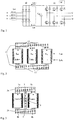
- Figs. 5a and 5b present an embodiment of a symmetrical implementation of a three-phase AC choke according to the invention.
- the phase-specific branches are formed of the semicircular magnetic cores 1r, 1s, 1t according to Fig. 5b and the windings R1, S1, T1 disposed around them.
- the phase-specific branches are disposed around the additional pillar 2c at 90° intervals according to Fig. 5a .
- the air gap 3c of the magnetic circuit can be situated e.g. according to Fig. 5b between the additional pillar and the phase-specific branches.
- An induction winding of line-to-earth short-circuit can be disposed around the additional pillar, with which the situation is detected in the same manner as in the case of a DC choke.
- Figs. 6a and 6b present another embodiment of an implementation of a three-phase AC choke according to the invention.
- the phase-specific branches are formed of the rectangular pillar parts 1R, 1S, 1T of the magnetic core that are positioned symmetrically at 120° intervals according to Fig. 6b , around which the windings R2, S2, T2 are disposed.
- the additional pillar 2d is in this embodiment triangular, in which case the phase-specific branches can be disposed around it symmetrically according to Fig. 6a .
Claims (11)
- Dreiphasige Wechselstrom- oder zweiphasige Gleichstromdrosselanordnung eines Frequenzumrichters,
in der ein Magnetkern vorhanden ist, in dem sich die phasenspezifischen Säulen der Wechselstromdrosselanordnung oder die zweigspezifischen Säulen der Gleichstromdrosselanordnung (1a, 1b, 1r, 1s, 1t, 1R, 1S, 1T) befinden, um die herum die phasenspezifischen Wicklungen der Wechselspannungsdrosselanordnung oder die zweigspezifischen Wicklungen der Gleichstromdrosselanordnung (Ldc1+, Ldc1-, R1, S1, T1, R2, S2, T2) angeordnet sind, um Differenzmodusströme zu filtern, und
bei der eine zusätzliche Säule (3, 2c, 2d) zur Dämpfung von Gleichtaktströmen im Magnetkern der Drossel angeordnet ist,
dadurch gekennzeichnet, dass
die zusätzliche Säule (3, 2c, 2d) ohne die phasenspezifischen oder zweigspezifischen Wicklungen um sie herum angeordnet ist, wobei in diesem Fall eine Dämpfung der Gleichtaktströme durch die Gleichtaktimpedanz, die durch die zusätzliche Säule ausgebildet wird, und durch die Wicklungen, die um die phasenspezifischen oder zweigspezifischen Säulen angeordnet sind, erreicht wird und
wobei sich um die zusätzliche Säule eine Wicklung (6) befindet, die einen Kleinsignalpegelimpuls in einer Phase-zu-Erde-Kurzschlusssituation ausbildet. - Drosselanordnung nach Anspruch 1, dadurch gekennzeichnet, dass die zusätzliche Säule ohne einen Luftspalt vorliegt.
- Drosselanordnung nach Anspruch 1, dadurch gekennzeichnet, dass die zusätzliche Säule aus einem anderen Material als die anderen Säulen ist.
- Drosselanordnung nach Anspruch 1, dadurch gekennzeichnet, dass die Querschnittsfläche des Wicklungsdrahts der Wicklung der zusätzlichen Säule kleiner ist als die Querschnittsfläche der Wicklungen der anderen Säulen.
- Drosselanordnung nach einem der Ansprüche 4, dadurch gekennzeichnet, dass die Wicklungszahl der Wicklung der zusätzlichen Säule kleiner ist als die Wicklungszahl der Wicklungen der anderen Säulen.
- Drosselanordnung nach einem der vorhergehenden Ansprüche, dadurch gekennzeichnet, dass die Querschnittsfläche der zusätzlichen Säule des Magnetkerns der Drossel kleiner ist als die Oberflächenfläche der anderen Säulen.
- Drosselanordnung einer dreiphasigen Wechselstromdrossel nach einem der vorhergehenden Ansprüche, dadurch gekennzeichnet, dass die phasenspezifischen Zweige aus halbkreisförmigen Magnetkernen (1r, 1s, 1t) gebildet sind, um welche Wicklungen (R1, S1, T1) angeordnet sind.
- Drosselanordnung einer dreiphasigen Wechselstromdrossel nach einem der Ansprüche 1 - 6, dadurch gekennzeichnet, dass die phasenspezifischen Zweige aus rechteckigen Säulenteilen des Magnetkerns (1R, 1S, 1T) gebildet sind, um welche Wicklungen (R2, S2, T2) angeordnet sind.
- Drosselanordnung einer dreiphasigen Wechselstromdrossel nach einem der vorhergehenden Ansprüche, dadurch gekennzeichnet, dass die zusätzliche Säule in ihrem Querschnitt rechteckig ist.
- Drosselanordnung einer dreiphasigen Wechselstromdrossel nach Anspruch 9,
dadurch gekennzeichnet, dass die phasenspezifischen Zweige in 90° Intervallen um die zusätzliche Säule (2c) herum angeordnet sind. - Drosselanordnung einer dreiphasigen Wechselstromdrossel nach einem der Ansprüche 1 - 8,
dadurch gekennzeichnet, dass die zusätzliche Säule (2d) in ihrem Querschnitt dreieckig ist und die phasenspezifischen Zweige um sie herum symmetrisch in 120° Intervallen angeordnet sind.
Applications Claiming Priority (1)
| Application Number | Priority Date | Filing Date | Title |
|---|---|---|---|
| FI20060925A FI119491B (fi) | 2006-10-20 | 2006-10-20 | Taajuusmuuttajan suotokuristinjärjestely |
Publications (2)
| Publication Number | Publication Date |
|---|---|
| EP1914868A1 EP1914868A1 (de) | 2008-04-23 |
| EP1914868B1 true EP1914868B1 (de) | 2017-12-27 |
Family
ID=37232190
Family Applications (1)
| Application Number | Title | Priority Date | Filing Date |
|---|---|---|---|
| EP07075855.2A Not-in-force EP1914868B1 (de) | 2006-10-20 | 2007-10-03 | Filterdrossel für einen Frequenzumrichter |
Country Status (3)
| Country | Link |
|---|---|
| US (1) | US7839251B2 (de) |
| EP (1) | EP1914868B1 (de) |
| FI (1) | FI119491B (de) |
Families Citing this family (18)
| Publication number | Priority date | Publication date | Assignee | Title |
|---|---|---|---|---|
| FI122043B (fi) * | 2008-08-13 | 2011-07-29 | Abb Oy | Taajuusmuuttajan kuristinlaite |
| US8502631B2 (en) | 2011-08-25 | 2013-08-06 | Ajax Tocco Magnethermic Corporation | Three-phase line reactor with skew yoke core design |
| DE102012207557A1 (de) * | 2012-05-07 | 2013-11-07 | Wobben Properties Gmbh | Dreiphasige Drossel |
| DE102012216693A1 (de) * | 2012-09-18 | 2014-03-20 | Schmidbauer Transformatoren und Gerätebau GmbH | 3-Phasen-Drossel mit Gleichtaktunterdrückungsverbindung |
| EP2782105B1 (de) * | 2013-03-20 | 2018-03-21 | Schneider Toshiba Inverter Europe SAS | Gegentakt- und Gleichtaktdrossel |
| WO2015054689A1 (en) * | 2013-10-11 | 2015-04-16 | Mte Corporation | Adjustable integrated combined common mode and differential mode three phase inductors and methods of manufacture and use thereof |
| GB201407338D0 (en) * | 2014-04-25 | 2014-06-11 | Gridon Ltd | Fault current limiter |
| CN104021920B (zh) * | 2014-05-27 | 2016-09-28 | 华为技术有限公司 | 耦合电感和功率变换器 |
| JP6228515B2 (ja) * | 2014-06-25 | 2017-11-08 | 株式会社日立製作所 | リアクトル並びにそれを用いた電力変換装置 |
| USD800061S1 (en) * | 2014-08-26 | 2017-10-17 | Tokuden Co., Ltd. | Transformer |
| US20180218826A1 (en) * | 2015-07-10 | 2018-08-02 | James MILLSAP | Magnetic core, and choke or transformer having such a magnetic core |
| EP3157022A1 (de) | 2015-10-16 | 2017-04-19 | SMA Solar Technology AG | Drosselanordnung und energieversorgungssystem unter verwendung derselben |
| JP6496237B2 (ja) | 2015-11-30 | 2019-04-03 | ファナック株式会社 | 各相で一定のインダクタンスが得られる多相リアクトル |
| DE102018206389A1 (de) * | 2018-04-25 | 2019-10-31 | Siemens Aktiengesellschaft | Dreiphasiger Transformator |
| JP6506462B2 (ja) * | 2018-11-08 | 2019-04-24 | ファナック株式会社 | 各相で一定のインダクタンスが得られる多相リアクトル |
| DE102019130838A1 (de) | 2019-11-15 | 2021-05-20 | Vacon Oy | Eine Filteranordnung |
| DE102019130839A1 (de) * | 2019-11-15 | 2021-05-20 | Vacon Oy | Eine Induktorbaugruppe |
| FR3132378A1 (fr) * | 2022-02-01 | 2023-08-04 | Valeo Siemens Eautomotive France Sas | Dispositif magnétique intégré |
Citations (1)
| Publication number | Priority date | Publication date | Assignee | Title |
|---|---|---|---|---|
| US5747981A (en) * | 1996-12-02 | 1998-05-05 | Ford Motor Company | Inductor for an electrical system |
Family Cites Families (12)
| Publication number | Priority date | Publication date | Assignee | Title |
|---|---|---|---|---|
| US1791719A (en) * | 1927-07-28 | 1931-02-10 | K W Ignition Corp | Transformer |
| JP2671434B2 (ja) | 1988-09-29 | 1997-10-29 | ソニー株式会社 | ノイズフィルタ用インダクタ |
| US5313176A (en) | 1992-10-30 | 1994-05-17 | Motorola Lighting, Inc. | Integrated common mode and differential mode inductor device |
| JP3317045B2 (ja) * | 1994-10-14 | 2002-08-19 | 株式会社村田製作所 | コモンモードチョークコイル |
| DE29616712U1 (de) | 1995-04-20 | 1996-12-19 | Schmidt Arno | Dreiphasen-Ringkern für Transformatoren oder Drosseln |
| US5731666A (en) | 1996-03-08 | 1998-03-24 | Magnetek Inc. | Integrated-magnetic filter having a lossy shunt |
| US5905642A (en) * | 1997-11-11 | 1999-05-18 | Robicon Corporation | Apparatus and method to reduce common mode voltage from current source drives |
| US6987372B1 (en) | 2001-04-11 | 2006-01-17 | Rockwell Automation Technologies, Inc. | Integrated DC link choke and method for suppressing common-mode voltage in a motor drive |
| US6617814B1 (en) * | 2001-04-11 | 2003-09-09 | Rockwell Automation Technologies, Inc. | Integrated DC link choke and method for suppressing common-mode voltage in a motor drive |
| US20030206087A1 (en) * | 2002-05-06 | 2003-11-06 | Square D Company | Magnetic system having three-dimensional symmetry for three phase transformers |
| JP4626389B2 (ja) | 2005-05-13 | 2011-02-09 | 富士電機システムズ株式会社 | 複合リアクトル |
| JP4404029B2 (ja) | 2005-08-09 | 2010-01-27 | 三菱電機株式会社 | ノイズフィルタ |
-
2006
- 2006-10-20 FI FI20060925A patent/FI119491B/fi not_active IP Right Cessation
-
2007
- 2007-10-03 EP EP07075855.2A patent/EP1914868B1/de not_active Not-in-force
- 2007-10-18 US US11/907,912 patent/US7839251B2/en active Active
Patent Citations (1)
| Publication number | Priority date | Publication date | Assignee | Title |
|---|---|---|---|---|
| US5747981A (en) * | 1996-12-02 | 1998-05-05 | Ford Motor Company | Inductor for an electrical system |
Also Published As
| Publication number | Publication date |
|---|---|
| FI20060925A0 (fi) | 2006-10-20 |
| FI20060925A (fi) | 2008-04-21 |
| FI119491B (fi) | 2008-11-28 |
| US20080094159A1 (en) | 2008-04-24 |
| EP1914868A1 (de) | 2008-04-23 |
| US7839251B2 (en) | 2010-11-23 |
Similar Documents
| Publication | Publication Date | Title |
|---|---|---|
| EP1914868B1 (de) | Filterdrossel für einen Frequenzumrichter | |
| CN103368407B (zh) | 电力变换器及其集成dc扼流器 | |
| US6617814B1 (en) | Integrated DC link choke and method for suppressing common-mode voltage in a motor drive | |
| CN102332808B (zh) | 包括差模和共模的逆变器滤波器以及包括该逆变器滤波器的系统 | |
| US7902956B2 (en) | Filtering choke arrangement | |
| US8212416B2 (en) | Device for filtering harmonics | |
| US11676787B2 (en) | Circuit breaker | |
| US7132812B1 (en) | Integrated DC link choke and method for suppressing common-mode voltage in a motor drive | |
| US6617950B2 (en) | Common mode/differential mode choke | |
| US7176779B2 (en) | Inductor arrangement | |
| US8866565B2 (en) | Systems and methods for providing an electric choke | |
| JP2009135271A (ja) | リアクトルおよびノイズフィルタ | |
| US8193889B2 (en) | Filter appliance for a multiphase electrical converter device | |
| US6987372B1 (en) | Integrated DC link choke and method for suppressing common-mode voltage in a motor drive | |
| EP2439756A2 (de) | Mehrphasentransformator | |
| KR20140081870A (ko) | 유도장치와 그 용도 | |
| Dzhankhotov et al. | A new passive hybrid air-core foil filter for modern power drives | |
| JP2001231268A (ja) | 電力変換装置 | |
| US11114992B2 (en) | Motor drive with a filter including a three-phase differential mode reactor with common mode damping | |
| WO2023119036A1 (en) | Electromagnetic interference filter | |
| EP3975210B1 (de) | Dreiphasige magnetanordnung mit einem einheitlichen kernkörper | |
| CN111433867A (zh) | 用于能电运行的机动车的共模-差模扼流圈 | |
| CN110610795A (zh) | 一种用于二相整流器的三相变压器 | |
| US11114932B1 (en) | Method and apparatus for reduction of ripple current | |
| US20230326646A1 (en) | Common mode choke for connecting to dc side of power converter, filter arrangement, and power converter |
Legal Events
| Date | Code | Title | Description |
|---|---|---|---|
| PUAI | Public reference made under article 153(3) epc to a published international application that has entered the european phase |
Free format text: ORIGINAL CODE: 0009012 |
|
| AK | Designated contracting states |
Kind code of ref document: A1 Designated state(s): AT BE BG CH CY CZ DE DK EE ES FI FR GB GR HU IE IS IT LI LT LU LV MC MT NL PL PT RO SE SI SK TR |
|
| AX | Request for extension of the european patent |
Extension state: AL BA HR MK RS |
|
| 17P | Request for examination filed |
Effective date: 20080701 |
|
| 17Q | First examination report despatched |
Effective date: 20080731 |
|
| AKX | Designation fees paid |
Designated state(s): AT BE BG CH CY CZ DE DK EE ES FI FR GB GR HU IE IS IT LI LT LU LV MC MT NL PL PT RO SE SI SK TR |
|
| RAP1 | Party data changed (applicant data changed or rights of an application transferred) |
Owner name: VACON OY |
|
| GRAP | Despatch of communication of intention to grant a patent |
Free format text: ORIGINAL CODE: EPIDOSNIGR1 |
|
| RIC1 | Information provided on ipc code assigned before grant |
Ipc: H02M 1/12 20060101AFI20170829BHEP Ipc: H01F 3/10 20060101ALI20170829BHEP |
|
| INTG | Intention to grant announced |
Effective date: 20171004 |
|
| GRAS | Grant fee paid |
Free format text: ORIGINAL CODE: EPIDOSNIGR3 |
|
| GRAA | (expected) grant |
Free format text: ORIGINAL CODE: 0009210 |
|
| AK | Designated contracting states |
Kind code of ref document: B1 Designated state(s): AT BE BG CH CY CZ DE DK EE ES FI FR GB GR HU IE IS IT LI LT LU LV MC MT NL PL PT RO SE SI SK TR |
|
| REG | Reference to a national code |
Ref country code: GB Ref legal event code: FG4D |
|
| REG | Reference to a national code |
Ref country code: CH Ref legal event code: EP |
|
| REG | Reference to a national code |
Ref country code: AT Ref legal event code: REF Ref document number: 959094 Country of ref document: AT Kind code of ref document: T Effective date: 20180115 |
|
| REG | Reference to a national code |
Ref country code: IE Ref legal event code: FG4D |
|
| REG | Reference to a national code |
Ref country code: DE Ref legal event code: R096 Ref document number: 602007053512 Country of ref document: DE |
|
| PG25 | Lapsed in a contracting state [announced via postgrant information from national office to epo] |
Ref country code: FI Free format text: LAPSE BECAUSE OF FAILURE TO SUBMIT A TRANSLATION OF THE DESCRIPTION OR TO PAY THE FEE WITHIN THE PRESCRIBED TIME-LIMIT Effective date: 20171227 Ref country code: LT Free format text: LAPSE BECAUSE OF FAILURE TO SUBMIT A TRANSLATION OF THE DESCRIPTION OR TO PAY THE FEE WITHIN THE PRESCRIBED TIME-LIMIT Effective date: 20171227 Ref country code: SE Free format text: LAPSE BECAUSE OF FAILURE TO SUBMIT A TRANSLATION OF THE DESCRIPTION OR TO PAY THE FEE WITHIN THE PRESCRIBED TIME-LIMIT Effective date: 20171227 |
|
| REG | Reference to a national code |
Ref country code: NL Ref legal event code: MP Effective date: 20171227 |
|
| REG | Reference to a national code |
Ref country code: LT Ref legal event code: MG4D |
|
| REG | Reference to a national code |
Ref country code: AT Ref legal event code: MK05 Ref document number: 959094 Country of ref document: AT Kind code of ref document: T Effective date: 20171227 |
|
| PG25 | Lapsed in a contracting state [announced via postgrant information from national office to epo] |
Ref country code: LV Free format text: LAPSE BECAUSE OF FAILURE TO SUBMIT A TRANSLATION OF THE DESCRIPTION OR TO PAY THE FEE WITHIN THE PRESCRIBED TIME-LIMIT Effective date: 20171227 Ref country code: BG Free format text: LAPSE BECAUSE OF FAILURE TO SUBMIT A TRANSLATION OF THE DESCRIPTION OR TO PAY THE FEE WITHIN THE PRESCRIBED TIME-LIMIT Effective date: 20180327 Ref country code: GR Free format text: LAPSE BECAUSE OF FAILURE TO SUBMIT A TRANSLATION OF THE DESCRIPTION OR TO PAY THE FEE WITHIN THE PRESCRIBED TIME-LIMIT Effective date: 20180328 |
|
| PG25 | Lapsed in a contracting state [announced via postgrant information from national office to epo] |
Ref country code: NL Free format text: LAPSE BECAUSE OF FAILURE TO SUBMIT A TRANSLATION OF THE DESCRIPTION OR TO PAY THE FEE WITHIN THE PRESCRIBED TIME-LIMIT Effective date: 20171227 |
|
| PG25 | Lapsed in a contracting state [announced via postgrant information from national office to epo] |
Ref country code: CY Free format text: LAPSE BECAUSE OF FAILURE TO SUBMIT A TRANSLATION OF THE DESCRIPTION OR TO PAY THE FEE WITHIN THE PRESCRIBED TIME-LIMIT Effective date: 20171227 Ref country code: SK Free format text: LAPSE BECAUSE OF FAILURE TO SUBMIT A TRANSLATION OF THE DESCRIPTION OR TO PAY THE FEE WITHIN THE PRESCRIBED TIME-LIMIT Effective date: 20171227 Ref country code: EE Free format text: LAPSE BECAUSE OF FAILURE TO SUBMIT A TRANSLATION OF THE DESCRIPTION OR TO PAY THE FEE WITHIN THE PRESCRIBED TIME-LIMIT Effective date: 20171227 Ref country code: ES Free format text: LAPSE BECAUSE OF FAILURE TO SUBMIT A TRANSLATION OF THE DESCRIPTION OR TO PAY THE FEE WITHIN THE PRESCRIBED TIME-LIMIT Effective date: 20171227 Ref country code: CZ Free format text: LAPSE BECAUSE OF FAILURE TO SUBMIT A TRANSLATION OF THE DESCRIPTION OR TO PAY THE FEE WITHIN THE PRESCRIBED TIME-LIMIT Effective date: 20171227 |
|
| PG25 | Lapsed in a contracting state [announced via postgrant information from national office to epo] |
Ref country code: IS Free format text: LAPSE BECAUSE OF FAILURE TO SUBMIT A TRANSLATION OF THE DESCRIPTION OR TO PAY THE FEE WITHIN THE PRESCRIBED TIME-LIMIT Effective date: 20180427 Ref country code: IT Free format text: LAPSE BECAUSE OF FAILURE TO SUBMIT A TRANSLATION OF THE DESCRIPTION OR TO PAY THE FEE WITHIN THE PRESCRIBED TIME-LIMIT Effective date: 20171227 Ref country code: AT Free format text: LAPSE BECAUSE OF FAILURE TO SUBMIT A TRANSLATION OF THE DESCRIPTION OR TO PAY THE FEE WITHIN THE PRESCRIBED TIME-LIMIT Effective date: 20171227 Ref country code: RO Free format text: LAPSE BECAUSE OF FAILURE TO SUBMIT A TRANSLATION OF THE DESCRIPTION OR TO PAY THE FEE WITHIN THE PRESCRIBED TIME-LIMIT Effective date: 20171227 Ref country code: PL Free format text: LAPSE BECAUSE OF FAILURE TO SUBMIT A TRANSLATION OF THE DESCRIPTION OR TO PAY THE FEE WITHIN THE PRESCRIBED TIME-LIMIT Effective date: 20171227 |
|
| REG | Reference to a national code |
Ref country code: DE Ref legal event code: R097 Ref document number: 602007053512 Country of ref document: DE |
|
| PLBE | No opposition filed within time limit |
Free format text: ORIGINAL CODE: 0009261 |
|
| STAA | Information on the status of an ep patent application or granted ep patent |
Free format text: STATUS: NO OPPOSITION FILED WITHIN TIME LIMIT |
|
| PG25 | Lapsed in a contracting state [announced via postgrant information from national office to epo] |
Ref country code: DK Free format text: LAPSE BECAUSE OF FAILURE TO SUBMIT A TRANSLATION OF THE DESCRIPTION OR TO PAY THE FEE WITHIN THE PRESCRIBED TIME-LIMIT Effective date: 20171227 |
|
| 26N | No opposition filed |
Effective date: 20180928 |
|
| PGFP | Annual fee paid to national office [announced via postgrant information from national office to epo] |
Ref country code: DE Payment date: 20180918 Year of fee payment: 12 |
|
| PG25 | Lapsed in a contracting state [announced via postgrant information from national office to epo] |
Ref country code: SI Free format text: LAPSE BECAUSE OF FAILURE TO SUBMIT A TRANSLATION OF THE DESCRIPTION OR TO PAY THE FEE WITHIN THE PRESCRIBED TIME-LIMIT Effective date: 20171227 |
|
| REG | Reference to a national code |
Ref country code: CH Ref legal event code: PL |
|
| GBPC | Gb: european patent ceased through non-payment of renewal fee |
Effective date: 20181003 |
|
| REG | Reference to a national code |
Ref country code: BE Ref legal event code: MM Effective date: 20181031 |
|
| PG25 | Lapsed in a contracting state [announced via postgrant information from national office to epo] |
Ref country code: LU Free format text: LAPSE BECAUSE OF NON-PAYMENT OF DUE FEES Effective date: 20181003 Ref country code: MC Free format text: LAPSE BECAUSE OF FAILURE TO SUBMIT A TRANSLATION OF THE DESCRIPTION OR TO PAY THE FEE WITHIN THE PRESCRIBED TIME-LIMIT Effective date: 20171227 |
|
| REG | Reference to a national code |
Ref country code: IE Ref legal event code: MM4A |
|
| PG25 | Lapsed in a contracting state [announced via postgrant information from national office to epo] |
Ref country code: FR Free format text: LAPSE BECAUSE OF NON-PAYMENT OF DUE FEES Effective date: 20181031 Ref country code: BE Free format text: LAPSE BECAUSE OF NON-PAYMENT OF DUE FEES Effective date: 20181031 Ref country code: LI Free format text: LAPSE BECAUSE OF NON-PAYMENT OF DUE FEES Effective date: 20181031 Ref country code: CH Free format text: LAPSE BECAUSE OF NON-PAYMENT OF DUE FEES Effective date: 20181031 |
|
| PG25 | Lapsed in a contracting state [announced via postgrant information from national office to epo] |
Ref country code: GB Free format text: LAPSE BECAUSE OF NON-PAYMENT OF DUE FEES Effective date: 20181003 Ref country code: IE Free format text: LAPSE BECAUSE OF NON-PAYMENT OF DUE FEES Effective date: 20181003 |
|
| PG25 | Lapsed in a contracting state [announced via postgrant information from national office to epo] |
Ref country code: MT Free format text: LAPSE BECAUSE OF NON-PAYMENT OF DUE FEES Effective date: 20181003 |
|
| PG25 | Lapsed in a contracting state [announced via postgrant information from national office to epo] |
Ref country code: TR Free format text: LAPSE BECAUSE OF FAILURE TO SUBMIT A TRANSLATION OF THE DESCRIPTION OR TO PAY THE FEE WITHIN THE PRESCRIBED TIME-LIMIT Effective date: 20171227 |
|
| REG | Reference to a national code |
Ref country code: DE Ref legal event code: R119 Ref document number: 602007053512 Country of ref document: DE |
|
| PG25 | Lapsed in a contracting state [announced via postgrant information from national office to epo] |
Ref country code: PT Free format text: LAPSE BECAUSE OF FAILURE TO SUBMIT A TRANSLATION OF THE DESCRIPTION OR TO PAY THE FEE WITHIN THE PRESCRIBED TIME-LIMIT Effective date: 20171227 |
|
| PG25 | Lapsed in a contracting state [announced via postgrant information from national office to epo] |
Ref country code: HU Free format text: LAPSE BECAUSE OF FAILURE TO SUBMIT A TRANSLATION OF THE DESCRIPTION OR TO PAY THE FEE WITHIN THE PRESCRIBED TIME-LIMIT; INVALID AB INITIO Effective date: 20071003 |
|
| PG25 | Lapsed in a contracting state [announced via postgrant information from national office to epo] |
Ref country code: DE Free format text: LAPSE BECAUSE OF NON-PAYMENT OF DUE FEES Effective date: 20200501 |