EP1914592A1 - Vibration reduction mechanism and optical device - Google Patents
Vibration reduction mechanism and optical device Download PDFInfo
- Publication number
- EP1914592A1 EP1914592A1 EP07118282A EP07118282A EP1914592A1 EP 1914592 A1 EP1914592 A1 EP 1914592A1 EP 07118282 A EP07118282 A EP 07118282A EP 07118282 A EP07118282 A EP 07118282A EP 1914592 A1 EP1914592 A1 EP 1914592A1
- Authority
- EP
- European Patent Office
- Prior art keywords
- moving member
- portions
- guide member
- engagement portions
- groove
- Prior art date
- Legal status (The legal status is an assumption and is not a legal conclusion. Google has not performed a legal analysis and makes no representation as to the accuracy of the status listed.)
- Withdrawn
Links
- 230000007246 mechanism Effects 0.000 title claims abstract description 49
- 230000009467 reduction Effects 0.000 title claims abstract description 36
- 230000003287 optical effect Effects 0.000 title claims description 7
- 238000001514 detection method Methods 0.000 description 3
- 229910000831 Steel Inorganic materials 0.000 description 2
- 230000008859 change Effects 0.000 description 2
- 239000000470 constituent Substances 0.000 description 2
- 238000010586 diagram Methods 0.000 description 2
- 230000004044 response Effects 0.000 description 2
- 239000010959 steel Substances 0.000 description 2
- 230000009471 action Effects 0.000 description 1
- 230000001627 detrimental effect Effects 0.000 description 1
- 238000006073 displacement reaction Methods 0.000 description 1
- 230000006870 function Effects 0.000 description 1
- 239000004973 liquid crystal related substance Substances 0.000 description 1
- 238000004519 manufacturing process Methods 0.000 description 1
- 230000004048 modification Effects 0.000 description 1
- 238000012986 modification Methods 0.000 description 1
- 238000005096 rolling process Methods 0.000 description 1
- 239000007787 solid Substances 0.000 description 1
- 238000004804 winding Methods 0.000 description 1
Images



Classifications
-
- G—PHYSICS
- G03—PHOTOGRAPHY; CINEMATOGRAPHY; ANALOGOUS TECHNIQUES USING WAVES OTHER THAN OPTICAL WAVES; ELECTROGRAPHY; HOLOGRAPHY
- G03B—APPARATUS OR ARRANGEMENTS FOR TAKING PHOTOGRAPHS OR FOR PROJECTING OR VIEWING THEM; APPARATUS OR ARRANGEMENTS EMPLOYING ANALOGOUS TECHNIQUES USING WAVES OTHER THAN OPTICAL WAVES; ACCESSORIES THEREFOR
- G03B5/00—Adjustment of optical system relative to image or object surface other than for focusing
-
- G—PHYSICS
- G02—OPTICS
- G02B—OPTICAL ELEMENTS, SYSTEMS OR APPARATUS
- G02B27/00—Optical systems or apparatus not provided for by any of the groups G02B1/00 - G02B26/00, G02B30/00
- G02B27/64—Imaging systems using optical elements for stabilisation of the lateral and angular position of the image
- G02B27/646—Imaging systems using optical elements for stabilisation of the lateral and angular position of the image compensating for small deviations, e.g. due to vibration or shake
-
- G—PHYSICS
- G03—PHOTOGRAPHY; CINEMATOGRAPHY; ANALOGOUS TECHNIQUES USING WAVES OTHER THAN OPTICAL WAVES; ELECTROGRAPHY; HOLOGRAPHY
- G03B—APPARATUS OR ARRANGEMENTS FOR TAKING PHOTOGRAPHS OR FOR PROJECTING OR VIEWING THEM; APPARATUS OR ARRANGEMENTS EMPLOYING ANALOGOUS TECHNIQUES USING WAVES OTHER THAN OPTICAL WAVES; ACCESSORIES THEREFOR
- G03B2205/00—Adjustment of optical system relative to image or object surface other than for focusing
- G03B2205/0007—Movement of one or more optical elements for control of motion blur
- G03B2205/0015—Movement of one or more optical elements for control of motion blur by displacing one or more optical elements normal to the optical axis
-
- G—PHYSICS
- G03—PHOTOGRAPHY; CINEMATOGRAPHY; ANALOGOUS TECHNIQUES USING WAVES OTHER THAN OPTICAL WAVES; ELECTROGRAPHY; HOLOGRAPHY
- G03B—APPARATUS OR ARRANGEMENTS FOR TAKING PHOTOGRAPHS OR FOR PROJECTING OR VIEWING THEM; APPARATUS OR ARRANGEMENTS EMPLOYING ANALOGOUS TECHNIQUES USING WAVES OTHER THAN OPTICAL WAVES; ACCESSORIES THEREFOR
- G03B2205/00—Adjustment of optical system relative to image or object surface other than for focusing
- G03B2205/0053—Driving means for the movement of one or more optical element
-
- G—PHYSICS
- G03—PHOTOGRAPHY; CINEMATOGRAPHY; ANALOGOUS TECHNIQUES USING WAVES OTHER THAN OPTICAL WAVES; ELECTROGRAPHY; HOLOGRAPHY
- G03B—APPARATUS OR ARRANGEMENTS FOR TAKING PHOTOGRAPHS OR FOR PROJECTING OR VIEWING THEM; APPARATUS OR ARRANGEMENTS EMPLOYING ANALOGOUS TECHNIQUES USING WAVES OTHER THAN OPTICAL WAVES; ACCESSORIES THEREFOR
- G03B2217/00—Details of cameras or camera bodies; Accessories therefor
- G03B2217/005—Blur detection
Definitions
- the present invention relates to a vibration reduction mechanism having a mechanism to correct blur of an optical system and an optical device using the vibration reduction mechanism.
- the above-mentioned vibration reduction mechanism has the disadvantage of including many constituent mechanical elements, thereby resulting in an insufficient regulation of the rotation of the lens frame body, due to errors and looseness between the constituent mechanical elements, which may be detrimental to the accuracy of the driving control of the vibration reduction mechanism.
- An object of the present invention is to provide a vibration reduction mechanism having a guide mechanism to guide a lens frame body, with a simple structure, and with high accuracy, and further to provide an optical device using the same.
- the present invention solves the above-mentioned problems in accordance with the following solving means.
- a vibration reduction mechanism comprises: a first moving member and a second moving member which move relatively at a time of blur correction; a guide member which guides relative movement of the first moving member and the second moving member; a plurality of first engagement portions, aligned in a row, which engage the first moving member and the guide member by spherical or cylindrical surfaces and groove-shaped portions; and a plurality of second engagement portions, aligned in a row, which engage the second moving member with the guide member by spherical or cylindrical surfaces and groove-shaped portions, wherein a groove shape of at least either one of the plurality of the first engagement portions or the plurality of the second engagement portions is formed with an elongated hole shape extending along an alignment direction of the first engagement portions aligned in a row.
- the spherical, cylindrical surface, or groove-shaped portions of the first engagement portion and the second engagement portion may be integrally formed with the guide member.
- the vibration reduction mechanism may further comprises one or more regulation portions between the first or second moving member and the guide member to regulate the relative movements along the alignment direction of the plurality of the first engagement portions aligned in a row.
- an optical device includes a vibration reduction mechanism, comprising: a first moving member and a second moving member which move relatively at a time of image blur correction; a guide member which guides relative movements of the first moving member and the second moving member; a plurality of first engagement portions, aligned in a row, which engage the first moving member with the guide member by spherical or cylindrical surfaces and groove-shaped portions; and a plurality of second engagement portions, aligned in a row, which engage the second moving member with the guide member by spherical or cylindrical surfaces and groove-shaped.
- the first and second engagement portions both having groove-shaped portions to engage with the spherical or cylindrical-shaped portions of the following guide member, the above-mentioned first and second engagement portions being disposed both between the guide member and the first moving member and between the guide member and the second moving member. Therefore, the first and second moving members can be relatively moved by means of a simple structure along a two-axis direction, without any relative rotation, with a constant orientation, and with a precise accuracy.
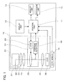
- FIG.1 is a block diagram showing an embodiment of a camera as a whole in accordance with the present invention.
- FIG.2 shows a lens barrel unit of the camera.
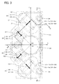
- FIG.3 is a plain view showing a vibration reduction mechanism provided in a lens barrel unit.
- FIG.4 is an A-A cross sectional view of FIG.3.
- FIG.5A and FIG.5B show a B-B cross sectional view of FIG.3.
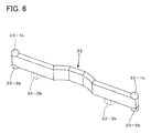
- FIG.6 is a perspective view of a guide member of the vibration reduction mechanism.
- the direction of light A1 which incidents to the camera 10 from a subject is shown as X direction
- the direction of the light A2 orthogonal to the light A1 is shown as the Z direction.
- the Y direction is orthogonal both to the X direction and Z direction.
- a camera 10 as shown in FIG.1 is a digital camera including: a control unit 11; a display unit 12; a memory unit 13; an operation unit 14; a gyro sensor 15; a lens barrel unit 20; and a vibration reduction mechanism unit 30.
- the control unit 11 is a CPU to supervise and control each unit of the camera 10, and further has a function to control the after-mentioned vibration reduction mechanism unit 30 in response to an output signal from a position detector 36 of the vibration reduction mechanism unit 30 and the gyro sensor 15.
- the display unit 12 is, for example, a liquid crystal display to display the images photographed by the camera 10 and the operating information.
- the memory unit 13 is a memory to store the image data photographed by the camera 10 and the operation data in the camera 10 and so on.
- the operation unit 14 includes a plurality of operation buttons to set up the photographing operations and photographing conditions for the camera 10, thereby executing operations such as an operation of an after-mentioned shutter diaphragm mechanism unit 29 (cf. FIG.2), and a zoom operation to drive a third lens unit 24 and a fifth lens unit 26 (cf. FIG.2).
- the gyro sensor 15 is a sensor to detect an angular velocity of the camera 10.
- the gyro sensor 15 detects movement (blurring caused by hand) thereby correcting the image blur caused by hand shake by means of the vibration reduction mechanism unit 30.
- the gyro sensor 15 includes two angular velocity sensors, each of which detects a pitching angular velocity (a rotation about the Y axis) and a yawing angular velocity (a rotation about the X axis).
- the lens barrel unit 20 as shown in FIG.1 and FIG.2 has: a first lens unit 21; a prism 22; a second lens unit 23; a third lens unit 24; a fourth lens unit 25; a fifth lens unit 26; a low pass filter 27; a CCD 28; a shutter diaphragm mechanism unit 29; and the vibration reduction mechanism unit 30.
- the first lens unit 21 is an objective lens upon which the light from the subject is incident, and the first lens unit 21 is the lens which is the nearest to the subject among the lens units in the lens barrel unit 20.
- the prism 22 is a rectangular prism to deflect by 90 degrees the incident light, whereby the light A1 along the +X direction exits from the first lens unit 21 is totally reflected and is deflected by 90 degrees, and the light A2 along the -Z direction exits toward the second lens unit 23.
- the second lens unit 23 is disposed at a position upon which the light A2 exiting from the prism 22 is incident.
- the third lens unit 24 is disposed at a position upon which the light A2 exiting from the second lens unit 23 is incident. Further, the third lens unit 24 can be moved to any position along the Z direction by a driving mechanism (not shown).
- the forth lens unit 25 is disposed, in a movable frame 31 of the vibration reduction mechanism unit 30, at a position upon which the light A2 exiting from the third lens unit 24 is incident.
- the fifth lens unit 26 is disposed at a position upon which the light A2 exiting from the forth lens unit 25 is incident. Further, the fifth lens unit 26, similarly to the third lens unit 24, can be moved to any positions along the Z direction by a driving mechanism (not shown).
- the low pass filter 27 is a filter to pass only a signal of a frequency less than or equal to a prescribed frequency, the low pass filter 27 being provided between the fifth lens unit 26 and the CCD 28 (cf. FIG.2), thereby preventing moire fringes of the image signal output from the CCD 28.
- the CCD (Charge-Coupled Device) 28 is a solid state image pick-up device provided at the exit side of the fifth lens unit 26 which can output an electrical image signal based on the light from the subject focused on the image pick-up surface.
- the shutter diaphragm mechanism unit 29 is disposed at the incident side of the fourth lens unit 25 of the vibration reduction mechanism unit 30.
- the shutter diaphragm mechanism unit 29 is provided with: a diaphragm portion to regulate a quantity of the subject light passing through the lens barrel unit 20; and a shutter unit to adjust the exposure time exposing the CCD 28 for the subject light.
- the vibration reduction mechanism unit 30 as shown in FIG.3 has: a movable frame (a first moving member) 31; a fixed frame (a second moving member) 32; a guide member 33; first engagement portions 33-1; second engagement portions 33-2; regulation portions 33-3; a support portion 34; voice coil motors (VCMs) 35; and position detectors 36.
- the movable frame 31 holding the forth lens unit 25 is moved, by means of driving sources of the VCMs 35 as an actuator, in the plane (XY plane) orthogonal to the light A2, thereby reducing the image blur caused by the movement of the camera 10 (hand blurring).
- the movable frame 31 holds the fourth lens unit 25 at the center of the movable frame 31, and is movable in the XY plane relative to the fixed frame 32. Further, there are provided, in the movable frame 31, on the surface opposite to the fixed frame 32, two groove-shaped portions 33-1a having an elongated hole shape, each of which forms a part of the after-mentioned first engagement portions 33-1. The two groove-shaped portions 33-1a are spaced at a sufficient distance.
- the fixed frame 32 is provided, at its center, with an opening for the light A2 exiting from the fourth lens unit 25 to pass through and fixed with the lens barrel unit 20.
- the two groove-shaped portions 33-2a are spaced at a sufficient distance.
- two concave portions 33-3a there are provided, at the above-mentioned same surface of the fixed frame 32, two concave portions 33-3a, each of which forms a part of the after-mentioned regulation portions 33-3.
- the guide member 33 as shown in FIG.4 through FIG.6 is a member elongating along the Y direction, and is disposed between the movable frame 31 and the fixed frame 32.
- spherically-shaped portions 33-1b each of which forms a part of the after-mentioned first engagement portions 33-1, at the two positions on a side (the upper side) of both edge of the guide member 33 opposite to the movable frame 31.
- spherically-shaped portions 33-2b each of which forms a part of the after-mentioned second engagement portions 33-2, at the two positions on another side (the lower side) of guide member 33 opposite to the fixed frame 32.
- convex portions 33-3b each of which forms a part of the after-mentioned regulation portion 33-3, at the two positions spaced by an equal distance from the center of the longitudinal direction (the Y direction).
- the first engagement portions 33-1 have: the groove-shaped portions 33-1a; and the spherically-shaped portions 33-1b.
- the first engagement portions 33-1 form a mechanism to guide the movable frame 31 and the guide member 33 by engaging the groove-shaped portions 33-1a with the spherically-shaped portions 33-1b. Therefore, both the groove-shaped portions 33-1a and the spherically-shaped portions 33-1b are disposed at the corresponding positions opposite to the movable frame 31 and the guide member 33, respectively, so as to be engaged with each other.
- the groove-shaped portions 33-1a are elongated holes extending in the Y direction in the movable frame 31.
- the second engagement portions 33-2 have: the groove-shaped portions 33-2a; and the spherically-shaped portions 33-2b, thereby guiding the fixed frame 32 and the guide member 33 by engaging the groove-shaped portions 33-2a with the spherically-shaped portions 33-2b. Therefore, the groove-shaped portions 33-2a and the spherically-shaped portions 33-2b are disposed at the corresponding positions opposite to the fixed frame 32 and the guide member 33, respectively, so as to be engaged with each other.
- the groove-shaped portions 33-2a are elongated holes extending along the Y direction in the fixed frame 32.
- the regulation portions 33-3 as shown in FIG.4 form a mechanism to regulate the guide member 33 so as not to move relatively to the fixed frame 32 along the Y direction.
- the regulation portions 33-3 having: the concave portions 33-3a provided on a surface of the fixed frame 32; and the convex portions 33-3b provided on a lower surface of the guide member 33.
- the concave portions 33-3a and the convex portions 33-3b are disposed at the corresponding positions opposite to the fixed frame 32 and the guide member 33, respectively, so as to be engaged with each other.
- the guide member 33 is integral moulded element, wherein the spherically-shaped portions 33-1b, spherically-shaped portions 33-2b and the convex portions 33-3b are integrally moulded. Further, the first engagement portions 33-1 and the second engagement portions 33-2 are provided around the voice coil motors 35 which is the action point of the force, in order for the guide member 33 to efficiently work relative to the movable frame 31 and the fixed frame 32.
- the movable frame 31 as shown in FIG.5B moves toward the X direction (as shown by the arrow B) relatively to the fixed frame 32 in such a manner that the guide member 33 inclines toward the X direction by means of both the first engagement portions 33-1 and the second engagement portion 33-2. Further, as shown in FIG.4, the movable frame 31 can move toward the Y direction (as shown by the arrow C) by means of the elongated hole groove-shaped portions 33-1a of the first engagement portions 33-1.
- the two sets of the groove-shaped portions 33-1a and the spherically-shaped portions 33-1b are spaced at a sufficient distance, and similarly, the two sets of the groove-shaped portions 33-2a and the spherically-shaped portions 33-2b are separated at a sufficient distance. Therefore, the movable frame 31 moves, without rotating itself around the fixed frame 32, and while holding it orientation constant. Further, the regulation portions 33-3 prevent the guide member 33 from independently moving between the movable frame 31 and the fixed frame 32.
- the support portion 34 is a rolling mechanism provided with: a steel ball 34-1; a cup-shaped sphere receiving portion 34-2; and a flat portion 34-3, whereby the steel ball 34-1 is held between the sphere receiving portion 34-2 provided at the fixed frame 32 and the flat portion 34-3 provided at the movable frame 31.
- This mechanism makes the movable frame 31 movable in the XY plane, holding constant its position along the Z direction.
- Each of the voice coil motors 35 as shown in FIG.3 and FIG.5A is a non-contact type electromagnetic actuator provided with: a magnet portion 35-1; and a coil portion 35-2, thereby linearly driving the fourth lens unit 25 in response to driving instructions and capable of responding at a high speed.
- the voice coil motors 35 are disposed at the two positions in lines symmetrical about the X axis passing through the center OR of the fourth lens unit 25 in the movable frame 31.
- the driving directions (the arrow C1 and the arrow C2) of the VCMs 35 are inclined by 45 degrees to the X direction, and the intersection point of the arrow C1 and the arrow C2 lies on the X axis passing through the center OR of the fourth lens unit 25.
- the magnet portion 35-1 is a magnetic circuit having: a permanent magnet 35-1a; and a yoke 35-1b.
- the coil portion 35-2 is a magnetic circuit having: a coil 35-2a as an armature winding wire; and a yoke 35-2b.
- the position detectors 36 is provided with: a magnet portion 36-1; and a detection portion 36-2, whereby, by detecting a magnetic field change between the magnet portion 36-1 and the detection portion 36-2, the displacement by the movement of the movable frame 31 is detected.
- the position detectors 36 are disposed at the two positions in lines symmetrical about the X axis passing through the center OR of the fourth lens unit 25 of the movable frame 31.
- the detecting directions (the arrow D1 and the arrow D2) of the position detectors 36 are inclined by 45 degrees to the X direction and the intersection point of each of the detecting directions (the arrow D1 and the arrow D2) lies on the X axis passing through the center OR of the fourth lens unit 25.
- the magnet portion 36-1 is a magnetic circuit having: a permanent magnet 36-1a; and a yoke 36-1b.
- the detection portion 36-2 is a magnetic circuit having: a Hall device 36-2a; and a yoke 36-2b.
- the camera 10 as shown in FIG.1 displays the subject image on the display unit 12 through the lens barrel unit 20 and takes the photographs of the subject by means of the operation unit 14.
- the lens barrel unit 20 makes the subject light incident on the first lens unit 21, deflects the subject light by 90 degrees by the prism 22, and focuses the subject light on the CCD 28 through from the second lens 23 to the fifth lens unit 26.
- the control unit 11 operates the vibration reduction mechanism 30, whereby the image blur due to hand shake caused by the user and so on is corrected.
- the image blur correction unit 30 executes, based on the angular velocity data of the orientation change of the camera 10 detected by the gyro sensor 15, and on the position data of the movable frame 31 relative to the fixed frame 32 detected by the position detector 36, the control to correct the image blur caused by the hand shake of the camera 10, and the optimal management of the relative position between the center portion of the fourth lens unit 25 and the light A2.
- the photographs of the subject can be clearly taken without being affected by external disturbances such as camera shake on the camera 10.
- the camera 10 of the present invention has the following advantages.
- the present invention is not limited to the above-explained embodiment. Various modifications and changes can be made.
Landscapes
- Physics & Mathematics (AREA)
- General Physics & Mathematics (AREA)
- Optics & Photonics (AREA)
- Adjustment Of Camera Lenses (AREA)
Abstract

Description
- The disclosure of the following priority applications is herein incorporated by reference:
Japanese Patent Application No. 2006-279579 filed on October 13, 2006 - The present invention relates to a vibration reduction mechanism having a mechanism to correct blur of an optical system and an optical device using the vibration reduction mechanism.
- There is known an optical device provided with a vibration reduction mechanism, in which a lens frame body is movable along a prescribed direction by sliding on a guide axis and rotates around the guide axis so that lens is supported to be movable along a direction perpendicular to the prescribed direction (for example, refer to
Japanese Unexamined Patent Application Publication No. H10-3102 - However, the above-mentioned vibration reduction mechanism has the disadvantage of including many constituent mechanical elements, thereby resulting in an insufficient regulation of the rotation of the lens frame body, due to errors and looseness between the constituent mechanical elements, which may be detrimental to the accuracy of the driving control of the vibration reduction mechanism.
- An object of the present invention is to provide a vibration reduction mechanism having a guide mechanism to guide a lens frame body, with a simple structure, and with high accuracy, and further to provide an optical device using the same.
- The present invention solves the above-mentioned problems in accordance with the following solving means.
- According to the first aspect of the present invention, a vibration reduction mechanism, comprises: a first moving member and a second moving member which move relatively at a time of blur correction; a guide member which guides relative movement of the first moving member and the second moving member; a plurality of first engagement portions, aligned in a row, which engage the first moving member and the guide member by spherical or cylindrical surfaces and groove-shaped portions; and a plurality of second engagement portions, aligned in a row, which engage the second moving member with the guide member by spherical or cylindrical surfaces and groove-shaped portions, wherein a groove shape of at least either one of the plurality of the first engagement portions or the plurality of the second engagement portions is formed with an elongated hole shape extending along an alignment direction of the first engagement portions aligned in a row.
- In the vibration reduction mechanism the spherical, cylindrical surface, or groove-shaped portions of the first engagement portion and the second engagement portion may be integrally formed with the guide member.
- The vibration reduction mechanism may further comprises one or more regulation portions between the first or second moving member and the guide member to regulate the relative movements along the alignment direction of the plurality of the first engagement portions aligned in a row.
- According to the second aspect of the present invention, an optical device, includes a vibration reduction mechanism, comprising: a first moving member and a second moving member which move relatively at a time of image blur correction; a guide member which guides relative movements of the first moving member and the second moving member; a plurality of first engagement portions, aligned in a row, which engage the first moving member with the guide member by spherical or cylindrical surfaces and groove-shaped portions; and a plurality of second engagement portions, aligned in a row, which engage the second moving member with the guide member by spherical or cylindrical surfaces and groove-shaped.
- In accordance with the present invention, there are provided, in the vibration reduction mechanism, the first and second engagement portions, both having groove-shaped portions to engage with the spherical or cylindrical-shaped portions of the following guide member, the above-mentioned first and second engagement portions being disposed both between the guide member and the first moving member and between the guide member and the second moving member. Therefore, the first and second moving members can be relatively moved by means of a simple structure along a two-axis direction, without any relative rotation, with a constant orientation, and with a precise accuracy.
-
- FIG. 1 is a block diagram showing an embodiment of a camera as a whole in accordance with the present invention.
- FIG. 2 shows a lens barrel unit of the camera in accordance with the present invention.
- FIG. 3 shows a vibration reduction mechanism of the camera in accordance with the present invention.
- FIG. 4 is an A-A cross sectional view of the vibration reduction mechanism of the camera in accordance with the present invention.
- FIG. 5A and FIG. 5B show a B-B cross sectional view of the vibration reduction mechanism of the camera in accordance with the present invention.
- FIG. 6 is a perspective view of a guide member of the vibration reduction mechanism in accordance with the present invention.
- In the following, referring to the drawings, an embodiment of the present invention is described in more detail.
- FIG.1 is a block diagram showing an embodiment of a camera as a whole in accordance with the present invention. FIG.2 shows a lens barrel unit of the camera. FIG.3 is a plain view showing a vibration reduction mechanism provided in a lens barrel unit. FIG.4 is an A-A cross sectional view of FIG.3. FIG.5A and FIG.5B show a B-B cross sectional view of FIG.3. FIG.6 is a perspective view of a guide member of the vibration reduction mechanism. For clarity, in FIG. 2 through FIG.5B, the direction of light A1 which incidents to the
camera 10 from a subject is shown as X direction, while the direction of the light A2 orthogonal to the light A1 is shown as the Z direction. Further, the Y direction is orthogonal both to the X direction and Z direction. - A
camera 10 as shown in FIG.1 is a digital camera including: acontrol unit 11; adisplay unit 12; amemory unit 13; anoperation unit 14; agyro sensor 15; alens barrel unit 20; and a vibrationreduction mechanism unit 30. - The
control unit 11 is a CPU to supervise and control each unit of thecamera 10, and further has a function to control the after-mentioned vibrationreduction mechanism unit 30 in response to an output signal from aposition detector 36 of the vibrationreduction mechanism unit 30 and thegyro sensor 15. - The
display unit 12 is, for example, a liquid crystal display to display the images photographed by thecamera 10 and the operating information. - The
memory unit 13 is a memory to store the image data photographed by thecamera 10 and the operation data in thecamera 10 and so on. - The
operation unit 14 includes a plurality of operation buttons to set up the photographing operations and photographing conditions for thecamera 10, thereby executing operations such as an operation of an after-mentioned shutter diaphragm mechanism unit 29 (cf. FIG.2), and a zoom operation to drive athird lens unit 24 and a fifth lens unit 26 (cf. FIG.2). - The
gyro sensor 15 is a sensor to detect an angular velocity of thecamera 10. Thegyro sensor 15 detects movement (blurring caused by hand) thereby correcting the image blur caused by hand shake by means of the vibrationreduction mechanism unit 30. Thegyro sensor 15 includes two angular velocity sensors, each of which detects a pitching angular velocity (a rotation about the Y axis) and a yawing angular velocity (a rotation about the X axis). - The
lens barrel unit 20 as shown in FIG.1 and FIG.2 has: afirst lens unit 21; aprism 22; asecond lens unit 23; athird lens unit 24; afourth lens unit 25; afifth lens unit 26; alow pass filter 27; aCCD 28; a shutterdiaphragm mechanism unit 29; and the vibrationreduction mechanism unit 30. - The
first lens unit 21 is an objective lens upon which the light from the subject is incident, and thefirst lens unit 21 is the lens which is the nearest to the subject among the lens units in thelens barrel unit 20. - The
prism 22 is a rectangular prism to deflect by 90 degrees the incident light, whereby the light A1 along the +X direction exits from thefirst lens unit 21 is totally reflected and is deflected by 90 degrees, and the light A2 along the -Z direction exits toward thesecond lens unit 23. - The
second lens unit 23 is disposed at a position upon which the light A2 exiting from theprism 22 is incident. - The
third lens unit 24 is disposed at a position upon which the light A2 exiting from thesecond lens unit 23 is incident. Further, thethird lens unit 24 can be moved to any position along the Z direction by a driving mechanism (not shown). - The forth
lens unit 25 is disposed, in amovable frame 31 of the vibrationreduction mechanism unit 30, at a position upon which the light A2 exiting from thethird lens unit 24 is incident. - The
fifth lens unit 26 is disposed at a position upon which the light A2 exiting from the forthlens unit 25 is incident. Further, thefifth lens unit 26, similarly to thethird lens unit 24, can be moved to any positions along the Z direction by a driving mechanism (not shown). - The
low pass filter 27 is a filter to pass only a signal of a frequency less than or equal to a prescribed frequency, thelow pass filter 27 being provided between thefifth lens unit 26 and the CCD 28 (cf. FIG.2), thereby preventing moire fringes of the image signal output from theCCD 28. - The CCD (Charge-Coupled Device) 28 is a solid state image pick-up device provided at the exit side of the
fifth lens unit 26 which can output an electrical image signal based on the light from the subject focused on the image pick-up surface. - The shutter
diaphragm mechanism unit 29 is disposed at the incident side of thefourth lens unit 25 of the vibrationreduction mechanism unit 30. The shutterdiaphragm mechanism unit 29 is provided with: a diaphragm portion to regulate a quantity of the subject light passing through thelens barrel unit 20; and a shutter unit to adjust the exposure time exposing theCCD 28 for the subject light. - The vibration
reduction mechanism unit 30 as shown in FIG.3 has: a movable frame (a first moving member) 31; a fixed frame (a second moving member) 32; aguide member 33; first engagement portions 33-1; second engagement portions 33-2; regulation portions 33-3; asupport portion 34; voice coil motors (VCMs) 35; andposition detectors 36. Themovable frame 31 holding the forthlens unit 25 is moved, by means of driving sources of theVCMs 35 as an actuator, in the plane (XY plane) orthogonal to the light A2, thereby reducing the image blur caused by the movement of the camera 10 (hand blurring). - The
movable frame 31 holds thefourth lens unit 25 at the center of themovable frame 31, and is movable in the XY plane relative to thefixed frame 32. Further, there are provided, in themovable frame 31, on the surface opposite to thefixed frame 32, two groove-shaped portions 33-1a having an elongated hole shape, each of which forms a part of the after-mentioned first engagement portions 33-1. The two groove-shaped portions 33-1a are spaced at a sufficient distance. - The fixed
frame 32 is provided, at its center, with an opening for the light A2 exiting from thefourth lens unit 25 to pass through and fixed with thelens barrel unit 20. There are provided, in the fixedframe 32, on the surface opposite to themovable frame 31, two groove-shaped portions 33-2a having an elongated hole shape, each of which forms a part of the after-mentioned second engagement portions 33-2. The two groove-shaped portions 33-2a are spaced at a sufficient distance. Further, there are provided, at the above-mentioned same surface of the fixedframe 32, two concave portions 33-3a, each of which forms a part of the after-mentioned regulation portions 33-3. - The
guide member 33 as shown in FIG.4 through FIG.6 is a member elongating along the Y direction, and is disposed between themovable frame 31 and the fixedframe 32. There are provided spherically-shaped portions 33-1b each of which forms a part of the after-mentioned first engagement portions 33-1, at the two positions on a side (the upper side) of both edge of theguide member 33 opposite to themovable frame 31. Similarly, there are provided spherically-shaped portions 33-2b each of which forms a part of the after-mentioned second engagement portions 33-2, at the two positions on another side (the lower side) ofguide member 33 opposite to the fixedframe 32. Further, there are provided, at an edge of theguide member 33 facing to the fixedframe 32, convex portions 33-3b each of which forms a part of the after-mentioned regulation portion 33-3, at the two positions spaced by an equal distance from the center of the longitudinal direction (the Y direction). - The first engagement portions 33-1 have: the groove-shaped portions 33-1a; and the spherically-shaped portions 33-1b. The first engagement portions 33-1 form a mechanism to guide the
movable frame 31 and theguide member 33 by engaging the groove-shaped portions 33-1a with the spherically-shaped portions 33-1b. Therefore, both the groove-shaped portions 33-1a and the spherically-shaped portions 33-1b are disposed at the corresponding positions opposite to themovable frame 31 and theguide member 33, respectively, so as to be engaged with each other. The groove-shaped portions 33-1a are elongated holes extending in the Y direction in themovable frame 31. - Similarly to the first engagement portions 33-1, the second engagement portions 33-2 have: the groove-shaped portions 33-2a; and the spherically-shaped portions 33-2b, thereby guiding the fixed
frame 32 and theguide member 33 by engaging the groove-shaped portions 33-2a with the spherically-shaped portions 33-2b. Therefore, the groove-shaped portions 33-2a and the spherically-shaped portions 33-2b are disposed at the corresponding positions opposite to the fixedframe 32 and theguide member 33, respectively, so as to be engaged with each other. The groove-shaped portions 33-2a are elongated holes extending along the Y direction in the fixedframe 32. - The regulation portions 33-3 as shown in FIG.4 form a mechanism to regulate the
guide member 33 so as not to move relatively to the fixedframe 32 along the Y direction. The regulation portions 33-3 having: the concave portions 33-3a provided on a surface of the fixedframe 32; and the convex portions 33-3b provided on a lower surface of theguide member 33. The concave portions 33-3a and the convex portions 33-3b are disposed at the corresponding positions opposite to the fixedframe 32 and theguide member 33, respectively, so as to be engaged with each other. - The
guide member 33 is integral moulded element, wherein the spherically-shaped portions 33-1b, spherically-shaped portions 33-2b and the convex portions 33-3b are integrally moulded. Further, the first engagement portions 33-1 and the second engagement portions 33-2 are provided around thevoice coil motors 35 which is the action point of the force, in order for theguide member 33 to efficiently work relative to themovable frame 31 and the fixedframe 32. - In accordance with the above-explained structure, the
movable frame 31 as shown in FIG.5B moves toward the X direction (as shown by the arrow B) relatively to the fixedframe 32 in such a manner that theguide member 33 inclines toward the X direction by means of both the first engagement portions 33-1 and the second engagement portion 33-2. Further, as shown in FIG.4, themovable frame 31 can move toward the Y direction (as shown by the arrow C) by means of the elongated hole groove-shaped portions 33-1a of the first engagement portions 33-1. Further, as shown in FIG.3, the two sets of the groove-shaped portions 33-1a and the spherically-shaped portions 33-1b are spaced at a sufficient distance, and similarly, the two sets of the groove-shaped portions 33-2a and the spherically-shaped portions 33-2b are separated at a sufficient distance. Therefore, themovable frame 31 moves, without rotating itself around the fixedframe 32, and while holding it orientation constant. Further, the regulation portions 33-3 prevent theguide member 33 from independently moving between themovable frame 31 and the fixedframe 32. - The
support portion 34, as shown in FIG.5A, is a rolling mechanism provided with: a steel ball 34-1; a cup-shaped sphere receiving portion 34-2; and a flat portion 34-3, whereby the steel ball 34-1 is held between the sphere receiving portion 34-2 provided at the fixedframe 32 and the flat portion 34-3 provided at themovable frame 31. This mechanism makes themovable frame 31 movable in the XY plane, holding constant its position along the Z direction. - Each of the
voice coil motors 35 as shown in FIG.3 and FIG.5A is a non-contact type electromagnetic actuator provided with: a magnet portion 35-1; and a coil portion 35-2, thereby linearly driving thefourth lens unit 25 in response to driving instructions and capable of responding at a high speed. Thevoice coil motors 35 are disposed at the two positions in lines symmetrical about the X axis passing through the center OR of thefourth lens unit 25 in themovable frame 31. The driving directions (the arrow C1 and the arrow C2) of theVCMs 35 are inclined by 45 degrees to the X direction, and the intersection point of the arrow C1 and the arrow C2 lies on the X axis passing through the center OR of thefourth lens unit 25. - The magnet portion 35-1 is a magnetic circuit having: a permanent magnet 35-1a; and a yoke 35-1b.
- The coil portion 35-2 is a magnetic circuit having: a coil 35-2a as an armature winding wire; and a yoke 35-2b.
- The
position detectors 36 is provided with: a magnet portion 36-1; and a detection portion 36-2, whereby, by detecting a magnetic field change between the magnet portion 36-1 and the detection portion 36-2, the displacement by the movement of themovable frame 31 is detected. Theposition detectors 36 are disposed at the two positions in lines symmetrical about the X axis passing through the center OR of thefourth lens unit 25 of themovable frame 31. The detecting directions (the arrow D1 and the arrow D2) of theposition detectors 36 are inclined by 45 degrees to the X direction and the intersection point of each of the detecting directions (the arrow D1 and the arrow D2) lies on the X axis passing through the center OR of thefourth lens unit 25. - The magnet portion 36-1 is a magnetic circuit having: a permanent magnet 36-1a; and a yoke 36-1b.
- The detection portion 36-2 is a magnetic circuit having: a Hall device 36-2a; and a yoke 36-2b.
- Next, the operation of the
camera 10 and the vibrationreduction mechanism unit 30 are described. - The
camera 10 as shown in FIG.1 displays the subject image on thedisplay unit 12 through thelens barrel unit 20 and takes the photographs of the subject by means of theoperation unit 14. Thelens barrel unit 20 makes the subject light incident on thefirst lens unit 21, deflects the subject light by 90 degrees by theprism 22, and focuses the subject light on theCCD 28 through from thesecond lens 23 to thefifth lens unit 26. When a user pushes the shutter button, thecontrol unit 11 operates thevibration reduction mechanism 30, whereby the image blur due to hand shake caused by the user and so on is corrected. - The image
blur correction unit 30 executes, based on the angular velocity data of the orientation change of thecamera 10 detected by thegyro sensor 15, and on the position data of themovable frame 31 relative to the fixedframe 32 detected by theposition detector 36, the control to correct the image blur caused by the hand shake of thecamera 10, and the optimal management of the relative position between the center portion of thefourth lens unit 25 and the light A2. In accordance with this mechanism, the photographs of the subject can be clearly taken without being affected by external disturbances such as camera shake on thecamera 10. - As explained above, the
camera 10 of the present invention has the following advantages. - (1) The first engagement portions 33-1 and the second engagement portions 33-2 engaged with the sphere-shaped portions 33-1b and 33-2b and the elongated hole groove portions 33-1a and 33-2a are provided both between the
guide member 33 and themovable frame 31 and between theguide member 33 and the fixedframe 32. Therefore, themovable frame 31 and the fixedframe 32 can be relatively moved along the two axial directions (the XY direction), with a simple structure, without any relative rotation, with a constant orientation, and with high accuracy. - (2) The spherically-shaped portions 33-1b and 33-2b of the first engagement portions 33-1 and the second engagement portions 33-2 are formed integrally with the
guide member 33. Therefore, any errors that may arise from these being separate parts are resolved, and the accuracy of the driving control of the vibrationreduction mechanism unit 30 can be improved. Further, the manufacturing cost can be reduced, because the spherically-shaped portions 33-1b and 33-2b and theguide member 33 can be integrally moulded. - (3) There are provided, between the fixed
frame 32 and theguide member 33, the regulation portions 33-3 to regulate the relative movements of the fixedframe 32 and theguide member 33, along the Y direction. Therefore, theguide member 33 can be prevented from independently moving between themovable frame 31 and the fixedframe 32, thereby improving the control characteristics and the accuracy of driving the vibrationreduction mechanism unit 30. - The present invention is not limited to the above-explained embodiment. Various modifications and changes can be made.
- (1) In the above-explained embodiment, the regulation portions 33-3 are provided between the fixed
frame 32 and themovable frame 31. However, the regulation portion 33-3 may be provided between themovable frame 31 and theguide member 33. - (2) In the above-explained embodiment the spherically-shaped portions 33-1b and 33-2b are employed for the first engagement portions 33-1 and the second engagement portions 33-2, respectively. However, cylindrically-shaped portions may be employed instead, with the condition that the center line of the cylinder is directed along the Y direction.
- (3) In the above-explained embodiment, the spherically-shaped portions 33-1b and 33-2b are formed in the
guide member 33, while the groove-shaped portions 33-1a and 33-2a, are formed in themovable frame 31 and in the fixedframe 32; however, the groove-shaped portions 33-1a and 33-2a may be formed, in theguide member 33, while the spherically-shaped portions 33-1b and 33-2b, respectively may be formed in themovable frame 31 and in the fixedframe 32.
Claims (5)
- A vibration reduction mechanism (30), comprising:a first moving member (31) and a second moving member (32) which move relatively at a time of blur correction;a guide member (33) which guides relative movement of the first moving member (31) and the second moving member (32);a plurality of first engagement portions (33-1), aligned in a row, which engage the first moving member (31) and the guide member (33) by spherical surface ( 33-1b) or cylindrical surface and groove-shaped portions (33-1a); anda plurality of second engagement portions (33-2), aligned in a row, which engage the second moving member (32) with the guide member (33) by spherical surface (33-2b) or cylindrical surface and groove-shaped portions (33-2a),wherein a groove shaped portions (33-1a, 33-2a) of at least either one of the plurality of the first engagement portions (33-1) or the plurality of the second engagement portions (33-2) is formed with an elongated hole shape extending along an alignment direction of the first engagement portions (33-1) aligned in a row.
- The vibration reduction mechanism (30) according to claim 1, wherein the spherical, cylindrical surface, or groove-shaped portions of the first engagement portion and the second engagement portion (33-1, 33-2) are integrally formed with the guide member (33).
- The vibration reduction mechanism (30) according to claim 1, further comprising a regulation portion (33-3) between the first or second moving member (31, 32) and the guide member (33) to regulate the relative movements along the alignment direction of the plurality of the first engagement portions (33-1) aligned in a row.
- The vibration reduction mechanism (30) according to claim 2, further comprising a regulation portion (33-3) between the first or second moving member (31, 32) and the guide member (33) to regulate the relative movements along the alignment direction of the plurality of the first engagement portions (33-1) aligned in a row.
- An optical device (10), including a vibration reduction mechanism (30), comprising:a first moving member (31) and a second moving member (32) which move relatively at a time of image blur correction;a guide member (33) which guides relative movements of the first moving member (31) and the second moving member (32);a plurality of first engagement portions (33-1), aligned in a row, which engage the first moving member (31) with the guide member (33) by spherical surface (33-1b) or cylindrical surface and groove-shaped portions (33-1a); anda plurality of second engagement portions (33-2), aligned in a row, which engage the second moving member (32) with the guide member (33) by spherical surface (33-2b) or cylindrical surface and groove-shaped portions (33-2a)wherein a groove shaped portions (33-1a, 33-2a) of at least either one of the plurality of the first engagement portions (33-1) or the plurality of the second engagement portions (33-2) is formed with an elongated hole shape extending along an alignment direction of the first engagement portions (33-1) aligned in a row.
Applications Claiming Priority (1)
| Application Number | Priority Date | Filing Date | Title |
|---|---|---|---|
| JP2006279579A JP4858068B2 (en) | 2006-10-13 | 2006-10-13 | Blur correction mechanism and optical device |
Publications (1)
| Publication Number | Publication Date |
|---|---|
| EP1914592A1 true EP1914592A1 (en) | 2008-04-23 |
Family
ID=39020893
Family Applications (1)
| Application Number | Title | Priority Date | Filing Date |
|---|---|---|---|
| EP07118282A Withdrawn EP1914592A1 (en) | 2006-10-13 | 2007-10-11 | Vibration reduction mechanism and optical device |
Country Status (4)
| Country | Link |
|---|---|
| US (1) | US7742692B2 (en) |
| EP (1) | EP1914592A1 (en) |
| JP (1) | JP4858068B2 (en) |
| CN (1) | CN101162347B (en) |
Cited By (1)
| Publication number | Priority date | Publication date | Assignee | Title |
|---|---|---|---|---|
| DE102012206230A1 (en) * | 2012-04-16 | 2013-10-17 | Carl Zeiss Sports Optics Gmbh | Optical system for imaging an object |
Families Citing this family (12)
| Publication number | Priority date | Publication date | Assignee | Title |
|---|---|---|---|---|
| US7974009B2 (en) * | 2007-09-19 | 2011-07-05 | Victor Company Of Japan, Limited | Image fluctuation correcting apparatus |
| JP5171282B2 (en) * | 2008-01-21 | 2013-03-27 | キヤノン株式会社 | Image shake correction apparatus, imaging apparatus, optical apparatus, and image shake correction apparatus control method |
| TWI369893B (en) * | 2008-06-18 | 2012-08-01 | Asia Optical Co Inc | Image detecting module |
| JP5369724B2 (en) * | 2009-01-30 | 2013-12-18 | 株式会社ニコン | Imaging device |
| JP5502456B2 (en) * | 2009-12-25 | 2014-05-28 | 日本電産コパル株式会社 | Image stabilization apparatus and imaging unit |
| KR101866482B1 (en) * | 2015-04-16 | 2018-06-11 | 코어포토닉스 리미티드 | Auto focus and optical image stabilization of compact folding camera |
| KR102166942B1 (en) * | 2017-02-20 | 2020-10-16 | 자화전자(주) | Apparatus for driving optical-reflector for ois with multi-axisal structure |
| JP6630331B2 (en) * | 2017-10-23 | 2020-01-15 | 新思考電機有限公司 | Lens drive device, camera device, and electronic device |
| JP7237685B2 (en) | 2019-03-28 | 2023-03-13 | 日本電産サンキョー株式会社 | Optical unit with anti-shake function |
| CN113067496B (en) * | 2019-12-31 | 2023-01-20 | 中芯集成电路(宁波)有限公司 | Piezoelectric driver, manufacturing method thereof and imaging module |
| CN120034736A (en) * | 2021-08-19 | 2025-05-23 | 谷歌有限责任公司 | Stabilization components for image sensors |
| CN122374571A (en) * | 2023-12-15 | 2026-07-10 | 株式会社日本显示器 | Light control device and lighting device |
Citations (5)
| Publication number | Priority date | Publication date | Assignee | Title |
|---|---|---|---|---|
| US5172276A (en) * | 1989-08-29 | 1992-12-15 | Minolta Camera Kabushiki Kaisha | Structure for stabilizing image in optical system |
| JPH103102A (en) | 1996-06-18 | 1998-01-06 | Nikon Corp | Image stabilizer |
| US5831671A (en) * | 1992-09-10 | 1998-11-03 | Canon Kabushiki Kaisha | Image blur prevention apparatus utilizing a stepping motor |
| US6064827A (en) | 1997-05-16 | 2000-05-16 | Canon Kabushiki Kaisha | Image stabilizer |
| US20060204233A1 (en) * | 2005-03-08 | 2006-09-14 | Nikon Corporation | Image vibration reduction apparatus and camera equipped with same |
Family Cites Families (7)
| Publication number | Priority date | Publication date | Assignee | Title |
|---|---|---|---|---|
| JPH0248135A (en) * | 1988-08-03 | 1990-02-16 | Nec Corp | Correcting mechanism for horizontally deviated position |
| JP3042092B2 (en) * | 1991-11-08 | 2000-05-15 | ダイキン工業株式会社 | Object handling equipment |
| JPH06118470A (en) * | 1992-10-07 | 1994-04-28 | Nikon Corp | Moving mechanism |
| US5854947A (en) * | 1996-06-18 | 1998-12-29 | Nikon Corporation | Vibration reducing apparatus |
| JPH10254012A (en) * | 1997-03-11 | 1998-09-25 | Minolta Co Ltd | Anti-vibration lens device |
| JPH117051A (en) * | 1997-06-16 | 1999-01-12 | Canon Inc | Lens shift device |
| JP2005217993A (en) * | 2004-01-30 | 2005-08-11 | Canon Inc | Imaging device |
-
2006
- 2006-10-13 JP JP2006279579A patent/JP4858068B2/en not_active Expired - Fee Related
-
2007
- 2007-10-10 US US11/907,290 patent/US7742692B2/en not_active Expired - Fee Related
- 2007-10-11 EP EP07118282A patent/EP1914592A1/en not_active Withdrawn
- 2007-10-12 CN CN2007101811827A patent/CN101162347B/en not_active Expired - Fee Related
Patent Citations (5)
| Publication number | Priority date | Publication date | Assignee | Title |
|---|---|---|---|---|
| US5172276A (en) * | 1989-08-29 | 1992-12-15 | Minolta Camera Kabushiki Kaisha | Structure for stabilizing image in optical system |
| US5831671A (en) * | 1992-09-10 | 1998-11-03 | Canon Kabushiki Kaisha | Image blur prevention apparatus utilizing a stepping motor |
| JPH103102A (en) | 1996-06-18 | 1998-01-06 | Nikon Corp | Image stabilizer |
| US6064827A (en) | 1997-05-16 | 2000-05-16 | Canon Kabushiki Kaisha | Image stabilizer |
| US20060204233A1 (en) * | 2005-03-08 | 2006-09-14 | Nikon Corporation | Image vibration reduction apparatus and camera equipped with same |
Cited By (1)
| Publication number | Priority date | Publication date | Assignee | Title |
|---|---|---|---|---|
| DE102012206230A1 (en) * | 2012-04-16 | 2013-10-17 | Carl Zeiss Sports Optics Gmbh | Optical system for imaging an object |
Also Published As
| Publication number | Publication date |
|---|---|
| CN101162347A (en) | 2008-04-16 |
| JP2008096773A (en) | 2008-04-24 |
| US20080088927A1 (en) | 2008-04-17 |
| JP4858068B2 (en) | 2012-01-18 |
| US7742692B2 (en) | 2010-06-22 |
| CN101162347B (en) | 2012-11-21 |
Similar Documents
| Publication | Publication Date | Title |
|---|---|---|
| US7742692B2 (en) | Vibration reduction mechanism and optical device | |
| EP2141539B1 (en) | Blurring correction device and optical apparatus | |
| US7623151B2 (en) | Vibration correcting device, lens barrel, and optical device | |
| US7907837B2 (en) | Image blur correction apparatus | |
| US7689109B2 (en) | Optical image stabilizer and optical apparatus | |
| JP4844177B2 (en) | Blur correction device and camera | |
| US7983545B2 (en) | Image blur correction unit, lens barrel device, and camera apparatus | |
| JP4764075B2 (en) | Image blur correction device and lens barrel provided with the image blur correction device | |
| EP2098901B1 (en) | Image blur correction unit, lens barrel device, and camera apparatus | |
| JP5012085B2 (en) | Blur correction device and optical device | |
| US7460775B2 (en) | Optical apparatus including efficiently arranged shake correction means | |
| JP4742558B2 (en) | Blur correction imaging apparatus and camera | |
| KR102815907B1 (en) | Driver ic and actuator of camera module including the same | |
| JP2010072625A (en) | Driving mechanism and optical equipment | |
| JP2017161665A (en) | Optical apparatus having image blur correction device | |
| JP2015227945A (en) | Blur correction device, lens barrel and photographing device | |
| US12474540B2 (en) | Driving apparatus and lens apparatus having the same | |
| JPH11258550A (en) | Optical device |
Legal Events
| Date | Code | Title | Description |
|---|---|---|---|
| PUAI | Public reference made under article 153(3) epc to a published international application that has entered the european phase |
Free format text: ORIGINAL CODE: 0009012 |
|
| AK | Designated contracting states |
Kind code of ref document: A1 Designated state(s): AT BE BG CH CY CZ DE DK EE ES FI FR GB GR HU IE IS IT LI LT LU LV MC MT NL PL PT RO SE SI SK TR |
|
| AX | Request for extension of the european patent |
Extension state: AL BA HR MK RS |
|
| 17P | Request for examination filed |
Effective date: 20081022 |
|
| 17Q | First examination report despatched |
Effective date: 20081124 |
|
| AKX | Designation fees paid |
Designated state(s): DE FR GB |
|
| RAP1 | Party data changed (applicant data changed or rights of an application transferred) |
Owner name: NIKON CORPORATION |
|
| RAP1 | Party data changed (applicant data changed or rights of an application transferred) |
Owner name: NIKON CORPORATION |
|
| GRAP | Despatch of communication of intention to grant a patent |
Free format text: ORIGINAL CODE: EPIDOSNIGR1 |
|
| RIC1 | Information provided on ipc code assigned before grant |
Ipc: G02B 27/64 20060101ALI20160212BHEP Ipc: G03B 5/00 20060101AFI20160212BHEP Ipc: G03B 17/00 20060101ALI20160212BHEP |
|
| INTG | Intention to grant announced |
Effective date: 20160309 |
|
| RIN1 | Information on inventor provided before grant (corrected) |
Inventor name: OMI, JUNICHI |
|
| STAA | Information on the status of an ep patent application or granted ep patent |
Free format text: STATUS: THE APPLICATION IS DEEMED TO BE WITHDRAWN |
|
| 18D | Application deemed to be withdrawn |
Effective date: 20160720 |