EP1914555A2 - Analyzer - Google Patents
Analyzer Download PDFInfo
- Publication number
- EP1914555A2 EP1914555A2 EP07019708A EP07019708A EP1914555A2 EP 1914555 A2 EP1914555 A2 EP 1914555A2 EP 07019708 A EP07019708 A EP 07019708A EP 07019708 A EP07019708 A EP 07019708A EP 1914555 A2 EP1914555 A2 EP 1914555A2
- Authority
- EP
- European Patent Office
- Prior art keywords
- reagent
- container
- mounting platform
- unit
- holder
- Prior art date
- Legal status (The legal status is an assumption and is not a legal conclusion. Google has not performed a legal analysis and makes no representation as to the accuracy of the status listed.)
- Withdrawn
Links
Images


Classifications
-
- G—PHYSICS
- G01—MEASURING; TESTING
- G01N—INVESTIGATING OR ANALYSING MATERIALS BY DETERMINING THEIR CHEMICAL OR PHYSICAL PROPERTIES
- G01N35/00—Automatic analysis not limited to methods or materials provided for in any single one of groups G01N1/00 - G01N33/00; Handling materials therefor
- G01N35/02—Automatic analysis not limited to methods or materials provided for in any single one of groups G01N1/00 - G01N33/00; Handling materials therefor using a plurality of sample containers moved by a conveyor system past one or more treatment or analysis stations
- G01N35/025—Automatic analysis not limited to methods or materials provided for in any single one of groups G01N1/00 - G01N33/00; Handling materials therefor using a plurality of sample containers moved by a conveyor system past one or more treatment or analysis stations having a carousel or turntable for reaction cells or cuvettes
-
- G—PHYSICS
- G01—MEASURING; TESTING
- G01N—INVESTIGATING OR ANALYSING MATERIALS BY DETERMINING THEIR CHEMICAL OR PHYSICAL PROPERTIES
- G01N35/00—Automatic analysis not limited to methods or materials provided for in any single one of groups G01N1/00 - G01N33/00; Handling materials therefor
- G01N35/10—Devices for transferring samples or any liquids to, in, or from, the analysis apparatus, e.g. suction devices, injection devices
- G01N35/1002—Reagent dispensers
-
- G—PHYSICS
- G01—MEASURING; TESTING
- G01N—INVESTIGATING OR ANALYSING MATERIALS BY DETERMINING THEIR CHEMICAL OR PHYSICAL PROPERTIES
- G01N35/00—Automatic analysis not limited to methods or materials provided for in any single one of groups G01N1/00 - G01N33/00; Handling materials therefor
- G01N2035/00346—Heating or cooling arrangements
- G01N2035/00435—Refrigerated reagent storage
-
- G—PHYSICS
- G01—MEASURING; TESTING
- G01N—INVESTIGATING OR ANALYSING MATERIALS BY DETERMINING THEIR CHEMICAL OR PHYSICAL PROPERTIES
- G01N35/00—Automatic analysis not limited to methods or materials provided for in any single one of groups G01N1/00 - G01N33/00; Handling materials therefor
- G01N35/02—Automatic analysis not limited to methods or materials provided for in any single one of groups G01N1/00 - G01N33/00; Handling materials therefor using a plurality of sample containers moved by a conveyor system past one or more treatment or analysis stations
- G01N35/04—Details of the conveyor system
- G01N2035/0401—Sample carriers, cuvettes or reaction vessels
- G01N2035/0406—Individual bottles or tubes
- G01N2035/041—Individual bottles or tubes lifting items out of a rack for access
-
- G—PHYSICS
- G01—MEASURING; TESTING
- G01N—INVESTIGATING OR ANALYSING MATERIALS BY DETERMINING THEIR CHEMICAL OR PHYSICAL PROPERTIES
- G01N35/00—Automatic analysis not limited to methods or materials provided for in any single one of groups G01N1/00 - G01N33/00; Handling materials therefor
- G01N35/02—Automatic analysis not limited to methods or materials provided for in any single one of groups G01N1/00 - G01N33/00; Handling materials therefor using a plurality of sample containers moved by a conveyor system past one or more treatment or analysis stations
- G01N35/04—Details of the conveyor system
- G01N2035/0439—Rotary sample carriers, i.e. carousels
- G01N2035/0443—Rotary sample carriers, i.e. carousels for reagents
Definitions
- the present invention relates to analyzers, in particular, to an analyzer equipped with a container holder for holding reagent containers.
- an analyzer for suctioning a reagent from a plurality of reagent containers mounted on a reagent table and analyzing a sample is known.
- the user needed to remove the reagent container to be replaced from the reagent table and mount a new reagent container to a predetermined position of the reagent table in such analyzer when reagent replacement was necessary.
- the user had to put his/her hand inside the accommodating unit of the reagent container in such analyzer, and thus the replacement task of the reagent was troublesome.
- An analyzer including a rotatable reagent storage in which reagent bottles are arranged, a reagent bottle supply mechanism for supplying the reagent bottle to the reagent storage, and a reagent bottle discharge mechanism for discharging the reagent bottle from the reagent storage is disclosed in Japanese Laid-Open Patent Publication No. 4-36658 .
- Such analyzer enables automatic replacement of the reagent bottle during analysis.
- An analyzer including a reagent disc for installing a reagent, a replenishing reagent cabinet arranged at a position different from the reagent disc, and a reagent holding means for conveying the reagent from the replenishing reagent cabinet to the reagent disc is disclosed in Japanese Laid-Open Patent Publication No. 2005-37171 .
- Such analyzer facilitates reagent replacement.
- the analyzer disclosed in Japanese Laid-Open Patent Publication No. 4-36658 has a complicating configuration since a belt line mechanism for conveying the reagent from a reagent bottle set yard to the reagent storage, and a belt line mechanism for conveying the reagent from the reagent storage to a reagent bottle discharge yard are necessary. Furthermore, in the analyzer disclosed in Japanese Laid-Open Patent Publication No. 4-36658 , a space for arranging the reagent bottle set yard, the belt line mechanisms, and the reagent bottle discharge yard is necessary, which enlarges the device.
- the analyzer disclosed in Japanese Laid-Open Patent Publication No. 2005-37171 has a complicating configuration since a mechanism (reagent holding means) for conveying the reagent in three-dimensional directions (XYZ directions) is necessary to convey the reagent from the replenishing reagent cabinet to the reagent disc. Furthermore, in the analyzer disclosed in Japanese Laid-Open Patent Publication No. 2005-37171 , a space for arranging the reagent holding means and the replenishment reagent cabinet is necessary, which enlarges the device.
- a first aspect of the present invention is an analyzer comprising: a reagent suction unit for suctioning reagent from a reagent container; an analyzing unit for analyzing an analyzing specimen comprising a sample and the reagent; a container raising and lowering unit comprising a mounting platform, wherein the container raising and lowering unit is configured to raise and lower the mounting platform; and a container holder configured to hold a plurality of reagent containers, wherein the container holder comprises a reagent container holding portion; wherein the mounting platform is configured to move a reagent container mounted thereon from a first position to a plurality of second positions, wherein the plurality of second positions comprises a position at which the reagent container is in contact with the reagent container holding portion
- a second aspect of the present invention is an analyzer comprising: a reagent suction unit for suctioning reagent from a reagent container; an analyzing unit for analyzing an analyzing specimen comprising a sample and the reagent; a container holder configured to hold a plurality of reagent containers in a circular ring form; a container raising and lowering unit configured for executing a mounting operation of mounting the reagent container on the container holder by lowering the reagent container, and a raising operation of raising the reagent container to a retrieving position above the container holder; and a rotation unit configured for moving at least one of the plurality of reagent containers to a raise waiting position, at which the reagent container starts rising, by rotating the plurality of reagent containers held by the container holder.
- a third aspect of the present invention is an analyzer comprising: a reagent suction unit for suctioning reagent from a reagent container; an analyzing unit for analyzing an analyzing specimen comprising a sample and the reagent; a container holder configured to hold a plurality of reagent containers; a mounting platform on which at least one of the plurality of reagent containers is mounted; and a driving source for moving the mounting platform to a first position, above the container holder, at which a reagent container is mounted and retrieved, and a second position, below the first position, at which a reagent container is held by the container holder.
- the immune analyzer 1 is an apparatus for carrying out examinations on various items such as hepatitis B, hepatitis C, tumor marker, and thyroid hormone using samples such as blood.
- magnetic particles R2 reagent
- R1 reagent trapped antibody
- an antigen contained in a sample such as blood which is the measuring object
- the bound antigen, trapped antibody, and magnetic particles are attracted to a magnet (not shown) of a BF (Bound Free) separator 14 (see Figs. 1 and 2) to remove the R1 reagent containing non-reactive (free) trapped body.
- a labeled antibody (R3 reagent) is bonded to the antigen bound with magnetic particles, and thereafter, the bound magnetic particles, antigen, and labeled antibody are attracted to a magnet of a BF separator 14 to remove a R3 reagent containing non-reactive (free) labeled antibody. Furthermore, a light emitting substrate (R5 reagent) that emits light in the reaction process with the labeled antibody is added, and a light emitting amount generated through the reaction of the labeled antibody and the light emitting substrate is measured. After such processes, the antigen or the antibody contained in the sample that bonds with the labeled antibody is quantitatively measured.
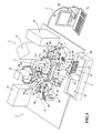
- the immune analyzer 1 includes a measurement mechanism section 2, a sample conveyance section (sampler) 3 arranged on the front surface side of the measurement mechanism section 2, and a control device 4 including PC (personal computer) electrically connected to the measurement mechanism section 2.
- the measurement mechanism section 2 is configured by a sample dispensing arm 5, reagent installing units 6 and 7, reagent dispensing arms 8, 9, and 10, a primary reaction unit 11 and a secondary reaction unit 12, a cuvette supplying unit 13, a BF separator 14, and a detector 15.
- a sample dispensing arm 5 is configured by a sample dispensing arm 5, reagent installing units 6 and 7, reagent dispensing arms 8, 9, and 10, a primary reaction unit 11 and a secondary reaction unit 12, a cuvette supplying unit 13, a BF separator 14, and a detector 15.
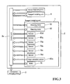
- each mechanism (various dispensing arms, reagent installing unit 6, and reagent installing unit 7, and the like) in the measurement mechanism section 2 are controlled by a control unit 2a arranged in the measurement mechanism section 2.
- the control unit 2a receives signals of various sensors (sensors 60d, 60g, 70a, 70b, 70c, 70d, and origin detection sensor 60e, and the like) arranged in the reagent installing unit 7, and controls the drive of various driving sources (stepping motors 53, 63, and motor 76, and the like) arranged in the reagent installing unit 7.
- the conveyance mechanism section 3 is also controlled by the control unit 2a.
- the various dispensing arms, various sensors, and various driving sources will be described in detail below.
- the control unit 2a is mainly configured by a CPU 2b, a ROM 2c, a RAM 2d, and a communication interface 2e.
- the CPU 2b executes computer programs stored in the ROM 2c and the computer programs read by the RAM 2d.
- the ROM 2c stores computer programs executed by the CPU 2b, data used in executing the computer program, and the like.
- the RAM 2d is used to read out the computer program stored in the ROM 2c. In executing the computer program, the ROM 2c is used as a work region of the CPU 2b.
- the communication interface 2e is connected to the control device 4, and transmits optical information (data of received light amount generated by reaction of the labeled antibody and light emitting substrate) of the sample to the control device 4, and receives signals from the control unit 4a of the control device 4.
- the communication interface 2e has a function of transmitting a command from the CPU 2b for driving each unit of the conveyance mechanism section 3 and the measurement mechanism section 2.
- the sample conveyance section 3 is configured to convey a rack 101 mounted with a plurality of test tubes 100 accommodating the sample to a position corresponding to a suction position 1a at where the sample dispensing arm 5 suctions the sample.
- the sample conveyance section 3 includes a rack set part 3a for setting the rack 101 in which the test tubes 100 accommodating non-processed sample are mounted, and a rack storing part 3b for storing the rack 101 in which the test tubes 100 accommodating the dispensing processed sample are mounted.
- the test tube 100 accommodating the non-processed sample is conveyed to a position corresponding to the suction position 1a of the sample dispensing arm 5, so that the sample dispensing arm 5 suctions the sample such as blood in the test tube 100, and thereafter, the rack 101 mounted with the test tube 100 is stored in the rack storing part 3b.
- the control device 4 (Fig. 1) consists of a personal computer (PC), and includes a control unit 4a including CPU, ROM, RAM, a display unit 4b and a keyboard 4c.
- the display unit 4b is arranged to display result of analysis obtained by analyzing data of digital signals transmitted from a detector 15.
- instruction for replacement, addition, and retrieval of a reagent-containing assembly 300 can be carried out in the control device 4.
- the control device 4 is configured by a computer 401 mainly consisting of the control unit 4a, the display unit 4b, and the keyboard 4c.
- the control unit 4a is mainly configured by a CPU 401a, a ROM 401b, a RAM 401c, a hard disc 401d, a read-out device 401e, an input/output interface 401f, a communication interface 401g, and an image output interface 401h.
- the CPU 401a, the ROM 401b, the RAM 401c, the hard disc 401d, the read-out device 401e, the input/output interface 401f, the communication interface 401g, and the image output interface 401h are connected by a bus 401i.
- the CPU 401a executes computer programs stored in the ROM 401b and the computer programs loaded in the RAM 401c.
- the computer 401 serves as the control device 4 when the CPU 401a executes the application program 404a, as hereinafter described.
- the ROM 401b is configured by mask ROM, PROM, EPROM, EEPROM, and the like, and is recorded with computer programs to be executed by the CPU 401a, data used for the same, and the like.
- the RAM 401c is configured by SRAM, DRAM, and the like.
- the RAM 401c is used to read out the computer programs recorded on the ROM 401b and the hard disc 401d.
- the RAM 401c is used as a work region of the CPU 401a when executing the computer programs.
- the hard disc 401d is installed with various computer programs to be executed by the CPU 401a such as operating system and application program, as well as data used in executing the computer program.
- the immune analysis application program 404a according to the present embodiment is also installed in the hard disc 401d.
- the read-out device 401e is configured by flexible disc drive, CD-ROM drive, DVD-ROM drive, and the like, and is able to read out computer programs and data recorded on a portable recording medium 404.
- the immune analysis application program 404a is stored in the portable recording medium 404, where the computer 401 reads out the application program 404a from the portable recording medium 404, and installs the application program 404a to the hard disc 401d.
- the application program 404a is not only provided by the portable recording medium 404, but also provided through communication line (wired or wireless) from external devices communicatably connected with the computer 401 through the communication line.
- the application program 404a may be stored in the hard disc of the server computer on the Internet, so that the computer 401 can access the server computer to download the application program 404a and install the application program 404a to the hard disc 401d.
- Operating system providing graphical user interface environment such as Windows (registered trademark) manufactured and sold by US Microsoft Co. is installed in the hard disc 401d.
- Windows registered trademark
- US Microsoft Co. operating system providing graphical user interface environment
- the application program 404a according to the first embodiment is assumed to operate on the operating system.
- the output interface 401f is configured by serial interface such as USB, IEEE1394, RS-232C; parallel interface such as SCSI, IDE, IEEE1284; analog interface such as D/A converter, A/D converter, and the like.
- the keyboard 4c is connected to the input/output interface 401f, so that the user can input data to the computer 401 using the keyboard 4c.
- the communication interface 401g is, for example, Ethernet (registered trademark) interface.
- the computer 401 transmits and receives data with the measurement mechanism section 2 using a predetermined communication protocol by means of the communication interface 401g.
- the image output interface 401h is connected to the display unit 4b configured by LCD, CRT, or the like, and is configured to output an image signal corresponding to the image data provided from the CPU 401a to the display unit 4b.
- the display unit 4b displays the image (screen) according to the input image signal.
- the immune analysis application program 404a installed in the hard disc 401d of the control unit 4a measures the amount of antigen or antibody in the measurement specimen using the received light amount (data of digital signal) of the measurement specimen transmitted from the detector 15 of the measurement mechanism section 2.
- the sample dispensing arm 5 (see Figs. 1 and 2) has a function of dispensing the sample in the test tube 100 conveyed to the suction position 1a by the sample conveyance section 3 into a cuvette 150 held by a holder 11b of a rotatable table 11a of the primary reaction unit 11 to be hereinafter described.
- the sample dispensing arm 5 includes a motor 5a, a drive transmitting part 5b connected to the motor 5a, and an arm 5d attached to the drive transmitting part 5b by way of a shaft 5c.
- the drive transmitting part 5b is configured to turn the arm 5d with the shaft 5c as the center by the driving force from the motor 5a, and move the arm in the up and down direction (Z direction).
- a pipette 5e for suctioning and discharging the sample is arranged at the distal end of the arm 5d.
- the reagent installing unit 6 (see Figs. 1 and 2) is arranged to install the reagent-containing assembly for holding a reagent container in which an R1 reagent containing trapped antibody is accommodated and a reagent container in which a R3 reagent containing labeled antibody is accommodated.
- the reagent installing unit 6 includes a reagent holder 20 for holding the reagent-containing assembly, a lid 30 attached to the reagent holder 20, and a raising and lowering unit 40 for replacing the reagent-containing assembly in the reagent holder 20 through a hole 30a formed in the lid 30.
- the reagent installing unit 7 (see Figs. 1 and 2) is arranged to install a reagent-containing assembly 300 (see Fig. 6) for holding a test container in which a R2 reagent containing magnetic particles is accommodated.
- the configuration of the reagent installing unit 7 will be hereinafter described in detail.
- the reagent dispensing arm 8 (see Figs. 1 and 2) has a function of suctioning the R1 reagent in the reagent-containing assembly installed in the reagent installing unit 6 and dispensing the suctioned R1 reagent into the cuvette 150 dispensed with the sample of the primary reaction unit 11.
- the reagent dispensing arm 8 includes a motor 8a, a drive transmitting part 8b connected to the motor 8a, and an arm 8d attached to the drive transmitting part 8b by way of a shaft 8c.
- the drive transmitting part 8b is configured to turn the arm 8d with the shaft 8c as the center by the driving force from the motor 8a, and move the arm in the up and down direction.
- a pipette 8e (see Fig.
- the pipette 8e is configured to suction the R1 reagent in the reagent-containing assembly installed in the reagent installing unit 6, and thereafter, dispense the suctioned R1 reagent into the cuvette 150 dispensed with the sample of the primary reaction unit 11.
- the reagent dispensing arm 9 (see Figs. 1 and 2) has a function of dispensing the R2 reagent in the reagent-containing assembly 300 installed in the reagent installing unit 7 into the cuvette 150 dispensed with the sample and the R1 reagent of the primary reaction unit 11.
- the reagent dispensing arm 9 includes a motor 9a, a drive transmitting part 9b connected to the motor 9a, and an arm 9d attached to the drive transmitting part 9b by way of a shaft 9c.
- the drive transmitting part 9b is configured to turn the arm 9d with the shaft 9c as the center by the driving force from the motor 9a, and move the arm in the up and down direction.
- a pipette 9e (see Fig.
- the pipette 9e is configured to suction the R2 reagent in the reagent-containing assembly 300 installed in the reagent installing unit 7, and thereafter, dispense the suctioned R2 reagent into the cuvette 150 dispensed with the sample and the R1 reagent of the primary reaction unit 11.
- the reagent dispensing arm 10 (see Figs. 1 and 2) has a function of suctioning the R3 reagent in the reagent-containing assembly installed in the reagent installing unit 6, and dispensing the suctioned R3 reagent into the cuvette 150 dispensed with the sample, the R1 reagent, and the R2 reagent of the secondary reaction unit 12.
- the reagent dispensing arm 10 includes a motor 10a, a drive transmitting part 10b connected to the motor 10a, and an arm 10d attached to the drive transmitting part 10b by way of a shaft 10c.
- the drive transmitting part 10b is configured to turn the arm 10d with the shaft 10c as the center by the driving force from the motor 10a, and move the arm in the up and down direction.
- a pipette 10e (see Fig. 1) for suctioning and discharging the R3 reagent in the reagent-containing assembly is arranged at the distal end of the arm 10d. That is, the pipette 10e is configured to suction the R3 reagent in the reagent-containing assembly installed in the reagent installing unit 6, and thereafter, dispense the suctioned R3 reagent into the cuvette 150 dispensed with the sample, the R1 reagent, and the R2 reagent of the secondary reaction unit 12.
- the primary reaction unit 11 is arranged to rotatably transfer the cuvette 150 held by the holder 11b of the rotatable table 11a by a predetermined angle for every predetermined period (18 seconds in the present embodiment), and to stir the sample, the R1 reagent, and the R2 reagent in the cuvette 150. That is, the primary reaction unit 11 is arranged to react the R2 reagent containing magnetic particles and the antigen in the sample in the cuvette 150.
- the primary reaction unit 11 is configured by a rotatable table 11a for conveying the cuvette 150 accommodating the sample, the R1 reagent, and the R2 reagent in the rotating direction, and a container conveying part 11c for stirring the sample, R1 reagent, and R2 reagent in the cuvette 150 and conveying the cuvette 150 accommodating the stirred sample, R1 reagent and R2 reagent to the BF separator 14 (see Figs. 1 and 2) to be hereinafter described.
- the rotatable table 11a is configured so as to rotatably transfer the cuvette 150 held in the holder 11b by a predetermined angle every 18 seconds.
- various devices sample dispensing arm 5, reagent dispensing arms 8 and 9 etc.
- various devices of the immune analyzer 1 are controlled so as to operate on the cuvette 150 at the predetermined transferred position at a timing the cuvette is transferred to the predetermined position by the rotatable table 11a.
- the container conveying part 11c is rotatably arranged at the central portion of the rotatable table 11a.
- the container conveying part 11c has a function of gripping the cuvette 150 held in the holder 11b of the rotatable table 11a and stirring the sample in the cuvette 150.
- the container conveying part 11c has a function of transferring the cuvette 150 accommodating the specimen obtained by stirring and incubating the sample, the R1 reagent and the R2 reagent to the BF separator 14 (see Figs. 1 and 2).
- the secondary reaction unit 12 (see Figs. 1 and 2) has a configuration similar to the primary reaction unit 11, and is arranged to rotatably transfer the cuvette 150 held by the holder 12b of the rotatable table 12a by a predetermined angle for every predetermined period (18 seconds in the present embodiment), and to stir the sample, the R1 reagent, the R2 reagent, the R3 reagent, and the R5 reagent in the cuvette 150. That is, the secondary reaction unit 12 is arranged to react the R3 reagent containing labeled antibody and the antigen in the sample in the cuvette 150, and to react the R5 reagent containing light emitting substrates and the labeled antibody of the R3 reagent.
- the R5 reagent is dispensed into the cuvette 150 accommodating the sample, the R1 reagent, the R2 reagent, and the R3 reagent of the secondary reaction unit 12 by a R5 reagent dispensing arm (not shown) arranged near the secondary reaction unit 12.
- the secondary reaction unit 12 is configured by a rotatable table 12a for conveying the cuvette 150 accommodating the sample, the R1 reagent, the R2 reagent, the R3 reagent, and the R5 reagent in the rotating direction, and a container conveying part 12c for stirring the sample, the R1 reagent, the R2 reagent, R3 reagent, and the R5 reagent in the cuvette 150 and conveying the cuvette 150 accommodating the stirred sample etc.
- the container conveying part 12c has a function of again conveying the cuvette 150 processed by the BF separator 14 to the holder 12b of the rotatable table 12.
- the detailed structure of the secondary reaction unit 12 is similar to the primary reaction unit 11, and thus the description thereof will be omitted.
- the cuvette supplying unit 13 (see Figs. 1 and 2) is configured to sequentially supply a plurality of cuvettes 150 to the holder 11b of the rotatable table 11a of the primary reaction unit 11.
- the BF separator 14 has a function of separating the non-reacting R1 reagent (unnecessary component) and the magnetic particles from the specimen in the cuvette 150 conveyed by the container conveying part 11c of the primary reaction unit 11, and a function of separating the non-reacting R3 reagent (unnecessary component) and the magnetic particles from the specimen in the cuvette 150 (see Fig. 1) conveyed by the container conveying part 12c of the secondary reaction unit 12.
- the detector 15 (see Figs. 1 and 2) is arranged to measure the amount of antigen contained in a sample by acquiring the light generated in the reaction process of the labeled antibody bound to the antigen of the sample performed with a predetermined process and the light emitting substrate with a photo multiplier tube.
- the reagent installing unit 7 includes a reagent holder 50 of cylindrical shape for holding the reagent-containing assembly 300 in a circular ring form, a lid 60 attached to the reagent holder 50 in an openable and closable manner, and a raising and lowering unit 70 attached to the side surface (outer wall part 51) of the cylindrical reagent holder 50.
- a Peltier element (not shown) is also attached at the bottom of the reagent installing unit 7, and the inside of the reagent installing unit 7 is maintained at about 15°C.
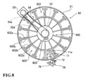
- the reagent holder 50 includes a cylindrical outer wall part 51, a rotatable rotation shaft 52 arranged at the center, a stepping motor 53 for rotating the rotation shaft 52, and a belt 54 for transmitting the driving force of the stepping motor 53 to the rotation shaft 52 (see Fig. 8).
- a heat insulating material (not shown) is attached over the entire surface on the inner surface of the outer wall part 51, so that the temperature inside the reagent holder 50 is maintained at low temperature (about 15°C).
- the driving force of the stepping motor 53 is transmitted to the rotation shaft 52 via the belt 54 by a pulley 53a that rotates by the stepping motor 53 and a pulley 52a coaxially fixed to the rotation shaft 52.
- a rack 600 for holding a plurality of reagent-containing assemblies 300 in a circular ring form is fixedly attached to the rotation shaft 52.
- the rack 600 holding the reagent-containing assemblies 300 rotates when the rotation shaft 52 is rotated with the reagent-containing assemblies 300 held in the rack 600, and thus the reagent-containing assembly 300 holding the reagent to be suctioned can be moved to below a hole 60b and an input/output hole 60c of the lid 60 to be hereinafter described.
- the rack 600 includes an inserting part 601, formed at the center of the rack 600, to which the rotation shaft 52 is inserted; a plurality of holders 602, formed in a circular ring form with the inserting part 601 as the center, for holding the reagent-containing assembly 300, and an origin detection strip 603 arranged so as to project above the inserting part 601.
- the holder 602 is configured by a partition plate 602a and a supporting part 602b.
- the partition plate 602a is arranged in plurals at a predetermined angular interval so as to radially extend from the inserting part 601.
- the supporting part 602b is arranged at the lower part of the portions facing each other of the partition plates 602a and at the lower part of the inserting part 601 so as to project to the inner side.
- Each reagent-containing assembly 300 is arranged such that the peripheral edge of the bottom 323 (see Fig. 18) is supported by the supporting part 602b in a space defined by a pair of partition plates 602a. Furthermore, as shown in Fig.
- the upper part and the lower part, as well as the outer sides in the radial direction of the holder 602 are formed as open ends, so that a mounting platform 71 and an arm 72 of the raising and lowering unit 70 for raising or lowering the reagent-containing assembly 300 can be raised or lowered without contacting the holder 602 of the rack 600.
- the lid 60 is attached in an openable and closable manner to the reagent holder 50 by way of a hinge part 60a.
- the lid 60 is configured to shield outside air so that the temperature in the reagent installing unit 7 is maintained at a low temperature (15°C), and so as to enable the reagent in the reagent installing unit 7 to be suctioned from the outside and the reagent-containing assembly 300 to be placed in or taken out from the reagent installing unit 7.
- the lid 60 has the hole 60b to be inserted with a pipette 9e of the reagent dispensing arm 9 when suctioning the reagent from the reagent container 310 (see Figs.
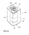
- the lid 60 includes an openable/closable member 61 for opening or closing a slide lid 322 (see Figs. 16 and 17) of the reagent-containing assembly 300 arranged below the hole 60b, a linear movement guide 62 for slidably supporting the openable/closable member 61, and a stepping motor 63 for driving the openable/closable member 61 in a reciprocating manner.
- the lid 60 is arranged with a reflection sensor 60d for detecting whether or not the reagent-containing assembly 300 is held in the holder 602 of the rack 600, a transmissive origin detection sensor 60e for detecting an origin position of the rack 600, a transmissive sensor 60f for detecting an origin position of the openable/closable member 61, and a transmissive sensor 60g for detecting the reagent-containing assembly 300 mounted on the mounting platform 71 of the raising and lowering unit 70, to be hereinafter described.
- the sensor 60d is arranged on the front surface side of the lid 60 so that light can be irradiated towards the back surface side of the lid 60, and the origin detection sensor 60e is arranged on the back surface side of the lid 60.
- the sensor 60f is arranged on the front surface side of the lid 60.
- the sensor 60g is arranged on the front surface side of the lid 60 so as to cross the input/output hole 60c.
- the openable/closable member 61 includes a two-forked engagement strip 61a, similar to an openable/closable member 31.
- the engagement strip 322a (see Fig. 16) of the slide lid 322 of the reagent-containing assembly 300 is positioned between the two-forked engagement strip 61a of the openable/closable member 61.
- a pair of guide strips 60h is attached in the vicinity of the hole 60b of the back surface of the lid 60.
- the pair of guide holes 60h has a function of contacting the engagement strip 322a of the slide lid 322 by the rotation of the rotation shaft 52 and guiding the same when arranged below the hole 60b with the slide lid 322 of the reagent-containing assembly 300 opened, thereby positioning the engagement strip 322a of the slide lid 322 between the two-forked engagement strip 61a of the openable/closable member 61.
- the reflection sensor 60d is configured to detect whether or not the reagent-containing assembly 300 is held in the holder 602 of the rack 600.
- the transmissive origin detection sensor 30e has a function of detecting the origin detection strip 603 arranged in the rack 600 to detect the origin position of the rotating rack 600.
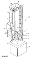
- the raising and lowering unit 70 is arranged to place in and take out the reagent-containing assembly 300 in the reagent installing unit 7.
- the raising and lowering unit 70 includes the mounting platform 71 to be mounted with the reagent-containing assembly 300, the arm 72 for supporting the mounting platform 71, a supporting member 73 for supporting the arm 72, a linear movement guide including a slider 74 fixed with the supporting member 73 and a guide rail 75 for slidably supporting the slider 74 in the up and down direction, a motor 76, a belt 77 for transmitting the driving force of the motor 76, and a bracket 78.
- Three transmissive sensors 70a, 70b, and 70c as well as a reflection sensor 70d are attached to the bracket 78.
- the mounting platform 71 has a function of holding the reagent-containing assembly 300 in the holder 602 of the rack 600 by being lowered with the reagent-containing assembly 300 mounted thereon.
- the mounting platform 71 has a function of lifting the reagent-containing assembly 300 of the holder 602 and taking out the reagent-containing assembly 300 from the input/output hole 60c of the lid 60 by being raised from below the holder 602 holding the reagent-containing assembly 300.
- a cross-shaped groove 71a that engages with a rib 323a (see Fig. 18) arranged at the bottom 323 of the reagent-containing assembly 300 is formed in the mounting platform 71. As shown in Fig.
- the arm 72 has a function of moving the mounting platform 71 in the up and down direction by the driving force of the motor 76 arranged exterior to the reagent holder 50 by way of a hole 51a extending in the up and down direction on the outer wall part 51.
- a blocking member (not shown) made of elastic material arranged with a slit that corresponds to the hole 51a is attached to the hole 51a.
- the arm 72 supports the mounting platform 71 by way of the slit.
- the blocking member suppresses cold air in the container holder 50 from leaking outside from the hole 51a without inhibiting the movement of the arm 52.
- a two-forked fixing strip 73a arranged on the supporting member 73 is fixed to the belt 77 with the belt 77 in between.
- the driving force of the motor 76 is transmitted to the supporting member 73 via the belt 77.
- a detection strip 73b is arranged in a projecting manner on the supporting member 73.
- the position in the up and down direction of the mounting platform 71 is detected when the detection strip 73b is detected by the sensors 70a, 70b, and 70c.
- the mounting platform 71 is positioned at a mounting/retrieving position (top dead point) at which the reagent-containing assembly 300 can be mounted and retrieved.
- the mounting platform 71 When the detection strip 73b is detected by the sensor 70b, the mounting platform 71 is positioned below (bottom dead point) the holder 602 of the rack 600.
- the mounting platform 71 is arranged below the reagent-containing assembly 300 held at the rack 600 when positioned at the bottom dead point, whereby the rack 600 can be rotated.
- a predetermined clearance region is provided between the rack 600 and the bottom dead point, and the sensor 70c detects the detection strip 73b.
- the control unit 2a can recognize that the mounting platform 71 is positioned in the clearance region between the holder 602 of rack 600 and the bottom dead point. Therefore, when the mounting platform 71 is positioned in the clearance region, the mounting platform 71 and the rack 600 are avoided from contacting each other when the rack 600 is rotated.
- the belt 77 is configured to be rotatably driven by a pulley (not shown) coaxially arranged on a rotation shaft (not shown) of the motor 76, and a pulley 77a arranged on
- the reflection sensor 70d detects the reagent-containing assembly 300 held in the holder 602 of the rack 600 by way of a hole 51b (see Fig. 15) arranged on the outer wall part 51 to monitor whether or not the replacement of the reagent-containing assembly 300 has been properly performed.
- the reagent-containing assembly 300 is made up of a reagent container 310 accommodating the R2 reagent, and a case 320 accommodating the reagent container 310.
- a slide lid 322 for sealing the reagent container 310 is formed on the upper surface 321 of the case 320.
- An engagement strip 322a for engaging the two-forked engagement strip 61a of the openable/closable member 61 is formed in the slide lid 322.
- a cross-shaped rib 323a that engages a groove 71a of the mounting platform 71 of the raising and lowering unit 70 is arranged in the bottom 323 of the case 320.
- a slit 324a (see Fig. 17) for visually recognizing the amount of reagent accommodated in the reagent container 310 is arranged on the side surface 324 of case 320.
- the reagent installing unit 6 has a configuration similar to the reagent installing unit 7 except for that two openable/closable mechanisms are arranged on the lid 30 in correspondence to the reagent-containing assembly including two reagent containers of R1 reagent and the R2 reagent, and thus the description thereof will be omitted.
- the mounting platform 71 is arranged at the mounting/retrieving position (state when the sensor 70a is ON) in the waiting state.
- the user first mounts the reagent-containing assembly 300 on the mounting platform 71, a shown in Figs. 19 and 21.
- the addition of the reagent-containing assembly 300 starts when the user instructs the addition of reagent by the control device 4 in this state.
- the rack 600 is rotated by the drive of the stepping motor 53 (see Fig. 8), and the holder 602 not holding the reagent-containing assembly 300 is moved to below the input/output hole 60c of the lid 60.
- the movement to below the mounting platform 71 starts by the drive of the motor 76, as shown in Fig. 20.
- the drive of the motor 76 is stopped.
- the rack 600 is rotated in this state by the drive of the stepping motor 53, and the holder 602 not holding the reagent-containing assembly 300 is moved to a waiting position below the input/output hole 60c (above the mounting platform 71 at the bottom dead point).
- the movement to the upper side of the mounting platform 71 then starts by the drive of the motor 76.
- the mounting platform 71 passes through the holder 602 not holding the reagent-containing assembly 300.
- the mounting platform 71 is then raised until the sensor 70a detects the detection strip 73b, and is arranged at the mounting/retrieving position.
- the addition of the reagent-containing assembly 300 is performed in such manner in the present embodiment.
- the user mounts the reagent-containing assembly 300 on the mounting platform 71 at the mounting/retrieving position, and then makes an instruction for replacement by the control device 4.
- the mounting platform 71 thereby lowers, the reagent-containing assembly 300 is held in the rack 600, and the mounting platform 71 moves to the bottom dead point (state when the sensor 70b is ON).
- the rack 600 is rotated by the drive of the stepping motor 53, and the holder 602 holding the reagent-containing assembly 300 to be replaced is moved to below the input/output hole 60c (above the mounting platform 71 at the bottom dead point).
- the movement to the upper side of the mounting platform 71 then starts by the drive of the motor 76.
- the mounting platform 71 that is being raised lifts the reagent-containing assembly 300 supported by the supporting part 602b of the holder 602, and further rises.
- the mounting platform 71 is raised until the sensor 70a detects the detection strip 73b, and is then arranged at the mounting/retrieving position.
- the reagent-containing assembly 300 to be replaced is thereby retrieved to the outside of the reagent installing unit 7.
- the replacement of the reagent-containing assembly 300 is performed in this manner in the present embodiment.
- the replacement, addition, and retrieval of the reagent-containing assembly in the reagent installing unit 6 are also performed similar to the reagent-containing assembly 300 in the reagent installing unit 7, and thus the description will be omitted.
- the reagent-containing assembly 300 including the reagent container 310 accommodating the reagent to be suctioned is moved to below the hole 60b of the lid 60 by rotating the rack 600 in which the rotation shaft 52 (see Fig. 8) of the reagent holder 50 holds the reagent-containing assembly 300.
- the engagement strip 322a of the slide lid 322 is arranged between the two-forked engagement strip 61a of the openable/closable member 61 of the lid 60, as shown in Fig. 23, if the slide lid 322 of the reagent-containing assembly 300 is closed when the reagent-containing assembly 300 is moved to below the hole 60b of the lid 60.
- the engagement strip 322a of the slide lid 322 is guided by a guide strip 60h (see Fig.
- the engagement strip 322a of the slide lid 322 is sled in a direction of the arrow A with the two-forked engagement strip 61a so that the slide lid 322 is in an opened state, as shown in Fig. 24.
- the pipette 9e of the reagent dispensing arm 9 then can be inserted into the reagent container 310.
- the pipette 9e is moved to the upper side of the hole 60b of the lid 60 through turning by the motor 9a and the drive transmitting part 9b, and the pipette 9e is lowered in the opened state of the slide lid 322 so that the pipette 9e can be inserted into the reagent container 310 through the hole 60b to suction the reagent.
- the pipette 9e that has suctioned the reagent is raised and turned by the motor 9a and the drive transmitting part 9b, and moved to the upper side of the primary reaction unit 11 (see Fig. 1).
- the reagent suctioned from the reagent container 310 is then dispensed into the cuvette 150 of the primary reaction unit 11.
- the turning member 61 is moved in a direction of the arrow B by the stepping motor 63, whereby the engagement strip 322a of the slide lid 322 is sled in the direction of the arrow B with the two-forked engagement strip 61a.
- the slide lid 322 is then closed, and the reagent is in the sealed state.
- the sealed state of the reagent is thus maintained even when the rack 600 is rotated and the reagent-containing assembly 300 is moved.
- the mounting platform 71 is lowered with the reagent-containing assembly 300 mounted on the mounting platform 71 at the mounting/retrieving position (state when the sensor 70a is ON) to hold the reagent-containing assembly 300 at the holder 602 of the rack 600, as described above.
- the holder 602 of the rack 600 holding the reagent-containing assembly 300 is arranged on the upper side of the mounting platform 71 at the bottom dead point (state when the sensor 70b is ON) and the mounting platform 71 is raised to lift the reagent-containing assembly 300 and retrieve the reagent-containing assembly 300 to the outside of the reagent installing unit 7.
- the immune analyzer 1 can be simplified and miniaturized.
- the user can mount the reagent-containing assembly 300 on the mounting platform 71 and retrieve the same at the mounting/retrieving position, and thus does not need to insert his/her hand into the reagent installing unit 7 when replacing the reagent-containing assembly 300.
- the reagent thus can be easily replaced.
- the movement of the mounting platform 71 is executed by the motor 76 when instruction for replacement, addition, and retrieval of the reagent-containing assembly 300 is made by the control device 4, as described above, so that the reagent can be replaced when the user instructs replacement of the reagent by the control device 4 as desired.
- the mounting platform 71 waits at the mounting/retrieving position until accepting instruction for replacement or addition of the reagent-containing assembly 300 by the control device 4, and when accepting instruction for replacement, addition, and retrieval, the raising and lowering unit 70 performs replacement, addition, and retrieval of the reagent-containing assembly 300, as described above, and thus the user can replace or add the reagent-containing assembly 300 without waiting for the mounting platform 71 to be raised to the mounting position since the mounting platform 71 is normally waiting at the mounting/retrieving position. Therefore, time from when the user instructs replacement and addition of the reagent-containing assembly 300 until a new reagent-containing assembly 300 is held by the holder 602 of the rack 600 can be reduced. The time of interrupting the analysis of the sample with replacement or addition of the reagent thus can be reduced.
- each of a plurality of reagent-containing assemblies 300 held in a circular ring form in the rack 600 can be arranged on a path of the mounting platform 71 by configuring the rack 600 holding the plurality of reagent-containing assemblies 300 in a circular ring form in a rotatable manner, as described above.
- the plurality of reagent-containing assemblies 300 held by the rack 600 thus can be replaced.
- the supporting part 602b configured to support the bottom 323 of the reagent-containing assembly 300 and to pass the mounting platform 71 when the mounting platform 71 is raised is arranged in the rack 60, as described above, whereby the reagent-containing assembly 300 can be supported by the supporting part 602b with the lowering operation of the mounting platform 71, and the reagent-containing assembly 300 can be lifted and retrieved by the mounting platform 71 with the rising operation of the mounting platform 71.
- the reagent-containing assembly 300 mounted on the mounting platform 71 can be held by the rack 600 without separately arranging a mechanism for moving the reagent-containing assembly 300 between the rack 600 and the mounting platform 71.
- the inside of the reagent installing unit 7 is cooled by the Peltier element, and the input/output hole 60c having a size that enables the reagent-containing assembly 300 to pass through is formed in the lid 60 so that the reagent-containing assembly 300 can be placed in and taken out from the input/output hole 60c, as described above, whereby the cooling by the Peltier element is efficiently performed while enabling replacement of the reagent-containing assembly 300.
- the present invention is not limited thereto, and may be applied to other analyzers such as biochemical analyzers and blood coagulation measurement devices.
- the mounting platform 71 waits at the mounting/retrieving position and when accepting instruction for reagent replacement, the mounting platform 71 is lowered so that the rack 600 holds a new reagent-containing assembly 300, and thereafter, the mounting platform 71 is raised so that the old reagent-containing assembly 300 is retrieved has been described, but the present invention is not limited thereto. That is, the mounting platform 71 may wait below the rack 600, and when accepting the instruction for reagent replacement, the mounting platform 71 may be raised so that the old reagent-containing assembly 300 is retrieved, and thereafter, the mounting platform 71 may be lowered with the new reagent-containing assembly 300 mounted by the user so that the rack 600 holds the reagent-containing assembly 300.
- the present invention is not limited thereto, and two raising and lowering units may be arranged in the reagent installing unit.
- one of the two raising and lowering units is the raising and lowering unit dedicated for addition, and the other is the raising and lowering unit dedicated for retrieval.
- the present invention is not limited thereto, and the used amount of reagent may be stored in the control unit, and the reagent-containing assembly to be replaced may be automatically retrieved when the used amount exceeds a predetermined amount and it is determined that the replacement of the reagent is necessary.
- a shutter may be arranged at a position corresponding to the mounting platform of the lid, and the user may mount the reagent-containing assembly 300 on the shutter when carrying out the replacement.
- the shutter opens so that the reagent-containing assembly is mounted on the mounting platform positioned immediately below the shutter. According to such configuration, the reagent in the reagent-containing assembly 300 can be more efficiently cooled.
- the mounting position and the retrieving position of the reagent-containing assembly 300 are both the upper dead point of the mounting platform 71, but the two positions may be different positions.
- the reagent-containing assembly 300 has the reagent container 310 accommodated in the case 320, and the R2 reagent accommodated in the reagent container 310, but the reagent container 310 does not need to be accommodated in the case 320, and the reagent container 310 itself may be the reagent-containing assembly.
Landscapes
- Chemical & Material Sciences (AREA)
- Physics & Mathematics (AREA)
- Health & Medical Sciences (AREA)
- Life Sciences & Earth Sciences (AREA)
- Analytical Chemistry (AREA)
- Biochemistry (AREA)
- General Health & Medical Sciences (AREA)
- General Physics & Mathematics (AREA)
- Immunology (AREA)
- Pathology (AREA)
- Chemical Kinetics & Catalysis (AREA)
- Automatic Analysis And Handling Materials Therefor (AREA)
Abstract
Description
- The present invention relates to analyzers, in particular, to an analyzer equipped with a container holder for holding reagent containers.
- Conventionally, an analyzer for suctioning a reagent from a plurality of reagent containers mounted on a reagent table and analyzing a sample is known. The user needed to remove the reagent container to be replaced from the reagent table and mount a new reagent container to a predetermined position of the reagent table in such analyzer when reagent replacement was necessary. However, the user had to put his/her hand inside the accommodating unit of the reagent container in such analyzer, and thus the replacement task of the reagent was troublesome.
- An analyzer that facilitates reagent replacement by the user is thus known (see e.g.,
Japanese Laid-Open Patent Publication No. 4-36658 Japanese Laid-Open Patent Publication No. 2005-37171 - An analyzer including a rotatable reagent storage in which reagent bottles are arranged, a reagent bottle supply mechanism for supplying the reagent bottle to the reagent storage, and a reagent bottle discharge mechanism for discharging the reagent bottle from the reagent storage is disclosed in
Japanese Laid-Open Patent Publication No. 4-36658 - An analyzer including a reagent disc for installing a reagent, a replenishing reagent cabinet arranged at a position different from the reagent disc, and a reagent holding means for conveying the reagent from the replenishing reagent cabinet to the reagent disc is disclosed in
Japanese Laid-Open Patent Publication No. 2005-37171 - However, the analyzer disclosed in
Japanese Laid-Open Patent Publication No. 4-36658 Japanese Laid-Open Patent Publication No. 4-36658 - The analyzer disclosed in
Japanese Laid-Open Patent Publication No. 2005-37171 Japanese Laid-Open Patent Publication No. 2005-37171 - The scope of the present invention is defined solely by the appended claims, and is not affected to any degree by the statements within this summary.
- A first aspect of the present invention is an analyzer comprising: a reagent suction unit for suctioning reagent from a reagent container; an analyzing unit for analyzing an analyzing specimen comprising a sample and the reagent; a container raising and lowering unit comprising a mounting platform, wherein the container raising and lowering unit is configured to raise and lower the mounting platform; and a container holder configured to hold a plurality of reagent containers, wherein the container holder comprises a reagent container holding portion; wherein the mounting platform is configured to move a reagent container mounted thereon from a first position to a plurality of second positions, wherein the plurality of second positions comprises a position at which the reagent container is in contact with the reagent container holding portion
- A second aspect of the present invention is an analyzer comprising: a reagent suction unit for suctioning reagent from a reagent container; an analyzing unit for analyzing an analyzing specimen comprising a sample and the reagent; a container holder configured to hold a plurality of reagent containers in a circular ring form; a container raising and lowering unit configured for executing a mounting operation of mounting the reagent container on the container holder by lowering the reagent container, and a raising operation of raising the reagent container to a retrieving position above the container holder; and a rotation unit configured for moving at least one of the plurality of reagent containers to a raise waiting position, at which the reagent container starts rising, by rotating the plurality of reagent containers held by the container holder.
- A third aspect of the present invention is an analyzer comprising: a reagent suction unit for suctioning reagent from a reagent container; an analyzing unit for analyzing an analyzing specimen comprising a sample and the reagent; a container holder configured to hold a plurality of reagent containers; a mounting platform on which at least one of the plurality of reagent containers is mounted; and a driving source for moving the mounting platform to a first position, above the container holder, at which a reagent container is mounted and retrieved, and a second position, below the first position, at which a reagent container is held by the container holder.
-
- Fig. 1 is a perspective view showing an overall configuration of an immune analyzer according to one embodiment of the present invention;
- Fig. 2 is a plan view of the immune analyzer shown in Fig. 1;
- Fig. 3 is a block diagram including a control unit of a measurement mechanism section of the immune analyzer according to one embodiment of the present invention;
- Fig. 4 is a block diagram showing a configuration of the control unit of the measurement mechanism section shown in Fig. 3;
- Fig. 5 is a block diagram showing a control device of the immune analyzer according to one embodiment of the present invention;
- Fig. 6 is a perspective view showing an overall configuration of a reagent installing unit shown in fig. 1;
- Fig. 7 is a perspective view showing a reagent holder of the reagent installing unit shown in Fig. 6;
- Fig. 8 is a plan view of the reagent holder of the reagent installing unit shown in Fig. 7;
- Fig. 9 is a perspective view showing a rack for holding the reagent-containing assembly used in the immune analyzer according to one embodiment of the present invention;
- Fig. 10 is a perspective view showing the reagent installing unit shown in Fig. 6;
- Fig. 11 is a perspective view showing a back surface of a lid of the reagent installing unit shown in Fig. 10;
- Fig. 12 is a perspective view showing a raising and lowering unit according to one embodiment;
- Fig. 13 is a perspective view showing the raising and lowering unit according to one embodiment;
- Fig. 14 is a plan view showing the raising and lowering unit according to one embodiment;
- Fig. 15 is a perspective view showing a hole formed in an outer wall part of the reagent holder according to one embodiment;
- Fig. 16 is an outer appearance view of the reagent-containing assembly used in the immune analyzer according to one embodiment of the present invention;
- Fig. 17 is an outer appearance view of the reagent-containing assembly used in the immune analyzer according to one embodiment of the present invention;
- Fig. 18 is a perspective view showing the bottom of the reagent-containing assembly shown in Fig. 16;
- Fig. 19 is a perspective view showing a state in which a mounting platform of the raising and lowering unit of the immune analyzer according to one embodiment is positioned at a mounting/retrieving position;
- Fig. 20 is a perspective view showing a state in which the mounting platform of the raising and lowering unit of the immune analyzer according to one embodiment is positioned at a bottom dead point;
- Fig. 21 is a cross sectional view taken along line 100-100 of Fig. 19;
- Fig. 22 is a cross sectional view taken along line 200-200 of Fig. 20;
- Fig. 23 is a cross sectional view showing a state in which a slide lid of the reagent-containing assembly is closed when suctioning the reagent; and
- Fig. 24 is a cross sectional view showing a state in which the slide lid of the reagent-containing assembly is opened when suctioning the reagent.
- The preferred embodiments of the present invention will be described hereinafter with reference to the drawings.
- An overall configuration of an
immune analyzer 1 according to one embodiment of the present invention will now be described with reference to Figs. 1 to 6. - The
immune analyzer 1 according to one embodiment of the present invention is an apparatus for carrying out examinations on various items such as hepatitis B, hepatitis C, tumor marker, and thyroid hormone using samples such as blood. In theimmune analyzer 1, magnetic particles (R2 reagent) are bonded to a trapped antibody (R1 reagent) bonded to an antigen contained in a sample such as blood, which is the measuring object, and thereafter, the bound antigen, trapped antibody, and magnetic particles are attracted to a magnet (not shown) of a BF (Bound Free) separator 14 (see Figs. 1 and 2) to remove the R1 reagent containing non-reactive (free) trapped body. A labeled antibody (R3 reagent) is bonded to the antigen bound with magnetic particles, and thereafter, the bound magnetic particles, antigen, and labeled antibody are attracted to a magnet of aBF separator 14 to remove a R3 reagent containing non-reactive (free) labeled antibody. Furthermore, a light emitting substrate (R5 reagent) that emits light in the reaction process with the labeled antibody is added, and a light emitting amount generated through the reaction of the labeled antibody and the light emitting substrate is measured. After such processes, the antigen or the antibody contained in the sample that bonds with the labeled antibody is quantitatively measured. - As shown in Figs. 1 and 2, the
immune analyzer 1 includes ameasurement mechanism section 2, a sample conveyance section (sampler) 3 arranged on the front surface side of themeasurement mechanism section 2, and acontrol device 4 including PC (personal computer) electrically connected to themeasurement mechanism section 2. Themeasurement mechanism section 2 is configured by asample dispensing arm 5,reagent installing units reagent dispensing arms primary reaction unit 11 and asecondary reaction unit 12, acuvette supplying unit 13, aBF separator 14, and adetector 15.
As shown in Fig. 3, each mechanism (various dispensing arms,reagent installing unit 6, andreagent installing unit 7, and the like) in themeasurement mechanism section 2 are controlled by acontrol unit 2a arranged in themeasurement mechanism section 2. Specifically, thecontrol unit 2a receives signals of various sensors (sensors origin detection sensor 60e, and the like) arranged in thereagent installing unit 7, and controls the drive of various driving sources (stepping motors motor 76, and the like) arranged in thereagent installing unit 7. Theconveyance mechanism section 3 is also controlled by thecontrol unit 2a. The various dispensing arms, various sensors, and various driving sources will be described in detail below. - The
control unit 2a is mainly configured by aCPU 2b, aROM 2c, aRAM 2d, and acommunication interface 2e. - The
CPU 2b executes computer programs stored in theROM 2c and the computer programs read by theRAM 2d. TheROM 2c stores computer programs executed by theCPU 2b, data used in executing the computer program, and the like. TheRAM 2d is used to read out the computer program stored in theROM 2c. In executing the computer program, theROM 2c is used as a work region of theCPU 2b. - The
communication interface 2e is connected to thecontrol device 4, and transmits optical information (data of received light amount generated by reaction of the labeled antibody and light emitting substrate) of the sample to thecontrol device 4, and receives signals from thecontrol unit 4a of thecontrol device 4. Thecommunication interface 2e has a function of transmitting a command from theCPU 2b for driving each unit of theconveyance mechanism section 3 and themeasurement mechanism section 2. - As shown in Figs. 1 and 2, the
sample conveyance section 3 is configured to convey arack 101 mounted with a plurality oftest tubes 100 accommodating the sample to a position corresponding to asuction position 1a at where thesample dispensing arm 5 suctions the sample. Thesample conveyance section 3 includes a rack setpart 3a for setting therack 101 in which thetest tubes 100 accommodating non-processed sample are mounted, and arack storing part 3b for storing therack 101 in which thetest tubes 100 accommodating the dispensing processed sample are mounted. Thetest tube 100 accommodating the non-processed sample is conveyed to a position corresponding to thesuction position 1a of thesample dispensing arm 5, so that thesample dispensing arm 5 suctions the sample such as blood in thetest tube 100, and thereafter, therack 101 mounted with thetest tube 100 is stored in therack storing part 3b. - The control device 4 (Fig. 1) consists of a personal computer (PC), and includes a
control unit 4a including CPU, ROM, RAM, adisplay unit 4b and akeyboard 4c. Thedisplay unit 4b is arranged to display result of analysis obtained by analyzing data of digital signals transmitted from adetector 15. In the present embodiment, instruction for replacement, addition, and retrieval of a reagent-containingassembly 300, to be hereinafter described, can be carried out in thecontrol device 4. - The configuration of the
control device 4 will now be described. As shown in Fig. 5, thecontrol device 4 is configured by acomputer 401 mainly consisting of thecontrol unit 4a, thedisplay unit 4b, and thekeyboard 4c. Thecontrol unit 4a is mainly configured by a CPU 401a, aROM 401b, aRAM 401c, ahard disc 401d, a read-outdevice 401e, an input/output interface 401f, acommunication interface 401g, and animage output interface 401h. The CPU 401a, theROM 401b, theRAM 401c, thehard disc 401d, the read-outdevice 401e, the input/output interface 401f, thecommunication interface 401g, and theimage output interface 401h are connected by abus 401i. - The CPU 401a executes computer programs stored in the
ROM 401b and the computer programs loaded in theRAM 401c. Thecomputer 401 serves as thecontrol device 4 when the CPU 401a executes theapplication program 404a, as hereinafter described. - The
ROM 401b is configured by mask ROM, PROM, EPROM, EEPROM, and the like, and is recorded with computer programs to be executed by the CPU 401a, data used for the same, and the like. - The
RAM 401c is configured by SRAM, DRAM, and the like. TheRAM 401c is used to read out the computer programs recorded on theROM 401b and thehard disc 401d. TheRAM 401c is used as a work region of the CPU 401a when executing the computer programs. - The
hard disc 401d is installed with various computer programs to be executed by the CPU 401a such as operating system and application program, as well as data used in executing the computer program. The immuneanalysis application program 404a according to the present embodiment is also installed in thehard disc 401d. - The read-out
device 401e is configured by flexible disc drive, CD-ROM drive, DVD-ROM drive, and the like, and is able to read out computer programs and data recorded on aportable recording medium 404. The immuneanalysis application program 404a is stored in theportable recording medium 404, where thecomputer 401 reads out theapplication program 404a from theportable recording medium 404, and installs theapplication program 404a to thehard disc 401d. - The
application program 404a is not only provided by theportable recording medium 404, but also provided through communication line (wired or wireless) from external devices communicatably connected with thecomputer 401 through the communication line. For instance, theapplication program 404a may be stored in the hard disc of the server computer on the Internet, so that thecomputer 401 can access the server computer to download theapplication program 404a and install theapplication program 404a to thehard disc 401d. - Operating system providing graphical user interface environment such as Windows (registered trademark) manufactured and sold by US Microsoft Co. is installed in the
hard disc 401d. In the following description, theapplication program 404a according to the first embodiment is assumed to operate on the operating system. - The
output interface 401f is configured by serial interface such as USB, IEEE1394, RS-232C; parallel interface such as SCSI, IDE, IEEE1284; analog interface such as D/A converter, A/D converter, and the like. Thekeyboard 4c is connected to the input/output interface 401f, so that the user can input data to thecomputer 401 using thekeyboard 4c. - The
communication interface 401g is, for example, Ethernet (registered trademark) interface. Thecomputer 401 transmits and receives data with themeasurement mechanism section 2 using a predetermined communication protocol by means of thecommunication interface 401g. - The
image output interface 401h is connected to thedisplay unit 4b configured by LCD, CRT, or the like, and is configured to output an image signal corresponding to the image data provided from the CPU 401a to thedisplay unit 4b. Thedisplay unit 4b displays the image (screen) according to the input image signal. - The immune
analysis application program 404a installed in thehard disc 401d of thecontrol unit 4a measures the amount of antigen or antibody in the measurement specimen using the received light amount (data of digital signal) of the measurement specimen transmitted from thedetector 15 of themeasurement mechanism section 2. - The sample dispensing arm 5 (see Figs. 1 and 2) has a function of dispensing the sample in the
test tube 100 conveyed to thesuction position 1a by thesample conveyance section 3 into acuvette 150 held by aholder 11b of a rotatable table 11a of theprimary reaction unit 11 to be hereinafter described. As shown in Figs. 1 and 2, thesample dispensing arm 5 includes amotor 5a, adrive transmitting part 5b connected to themotor 5a, and anarm 5d attached to thedrive transmitting part 5b by way of ashaft 5c. Thedrive transmitting part 5b is configured to turn thearm 5d with theshaft 5c as the center by the driving force from themotor 5a, and move the arm in the up and down direction (Z direction). Apipette 5e for suctioning and discharging the sample is arranged at the distal end of thearm 5d. - The reagent installing unit 6 (see Figs. 1 and 2) is arranged to install the reagent-containing assembly for holding a reagent container in which an R1 reagent containing trapped antibody is accommodated and a reagent container in which a R3 reagent containing labeled antibody is accommodated. As shown in Fig. 1, the
reagent installing unit 6 includes areagent holder 20 for holding the reagent-containing assembly, alid 30 attached to thereagent holder 20, and a raising and loweringunit 40 for replacing the reagent-containing assembly in thereagent holder 20 through ahole 30a formed in thelid 30. - The reagent installing unit 7 (see Figs. 1 and 2) is arranged to install a reagent-containing assembly 300 (see Fig. 6) for holding a test container in which a R2 reagent containing magnetic particles is accommodated. The configuration of the
reagent installing unit 7 will be hereinafter described in detail. - The reagent dispensing arm 8 (see Figs. 1 and 2) has a function of suctioning the R1 reagent in the reagent-containing assembly installed in the
reagent installing unit 6 and dispensing the suctioned R1 reagent into thecuvette 150 dispensed with the sample of theprimary reaction unit 11. Thereagent dispensing arm 8 includes amotor 8a, adrive transmitting part 8b connected to themotor 8a, and anarm 8d attached to thedrive transmitting part 8b by way of ashaft 8c. Thedrive transmitting part 8b is configured to turn thearm 8d with theshaft 8c as the center by the driving force from themotor 8a, and move the arm in the up and down direction. Apipette 8e (see Fig. 1) for suctioning and discharging the R1 reagent in the reagent-containing assembly is arranged at the distal end of thearm 8d. That is, thepipette 8e is configured to suction the R1 reagent in the reagent-containing assembly installed in thereagent installing unit 6, and thereafter, dispense the suctioned R1 reagent into thecuvette 150 dispensed with the sample of theprimary reaction unit 11. - The reagent dispensing arm 9 (see Figs. 1 and 2) has a function of dispensing the R2 reagent in the reagent-containing
assembly 300 installed in thereagent installing unit 7 into thecuvette 150 dispensed with the sample and the R1 reagent of theprimary reaction unit 11. The reagent dispensing arm 9 includes amotor 9a, adrive transmitting part 9b connected to themotor 9a, and anarm 9d attached to thedrive transmitting part 9b by way of ashaft 9c. Thedrive transmitting part 9b is configured to turn thearm 9d with theshaft 9c as the center by the driving force from themotor 9a, and move the arm in the up and down direction. Apipette 9e (see Fig. 1) for suctioning and discharging the R2 reagent in the reagent-containingassembly 300 is arranged at the distal end of thearm 9d. Thus, thepipette 9e is configured to suction the R2 reagent in the reagent-containingassembly 300 installed in thereagent installing unit 7, and thereafter, dispense the suctioned R2 reagent into thecuvette 150 dispensed with the sample and the R1 reagent of theprimary reaction unit 11. - The reagent dispensing arm 10 (see Figs. 1 and 2) has a function of suctioning the R3 reagent in the reagent-containing assembly installed in the
reagent installing unit 6, and dispensing the suctioned R3 reagent into thecuvette 150 dispensed with the sample, the R1 reagent, and the R2 reagent of thesecondary reaction unit 12. Thereagent dispensing arm 10 includes amotor 10a, adrive transmitting part 10b connected to themotor 10a, and anarm 10d attached to thedrive transmitting part 10b by way of ashaft 10c. Thedrive transmitting part 10b is configured to turn thearm 10d with theshaft 10c as the center by the driving force from themotor 10a, and move the arm in the up and down direction. A pipette 10e (see Fig. 1) for suctioning and discharging the R3 reagent in the reagent-containing assembly is arranged at the distal end of thearm 10d. That is, the pipette 10e is configured to suction the R3 reagent in the reagent-containing assembly installed in thereagent installing unit 6, and thereafter, dispense the suctioned R3 reagent into thecuvette 150 dispensed with the sample, the R1 reagent, and the R2 reagent of thesecondary reaction unit 12. - As shown in Figs. 1 and 2, the
primary reaction unit 11 is arranged to rotatably transfer thecuvette 150 held by theholder 11b of the rotatable table 11a by a predetermined angle for every predetermined period (18 seconds in the present embodiment), and to stir the sample, the R1 reagent, and the R2 reagent in thecuvette 150.
That is, theprimary reaction unit 11 is arranged to react the R2 reagent containing magnetic particles and the antigen in the sample in thecuvette 150. Theprimary reaction unit 11 is configured by a rotatable table 11a for conveying thecuvette 150 accommodating the sample, the R1 reagent, and the R2 reagent in the rotating direction, and acontainer conveying part 11c for stirring the sample, R1 reagent, and R2 reagent in thecuvette 150 and conveying thecuvette 150 accommodating the stirred sample, R1 reagent and R2 reagent to the BF separator 14 (see Figs. 1 and 2) to be hereinafter described. - The rotatable table 11a is configured so as to rotatably transfer the
cuvette 150 held in theholder 11b by a predetermined angle every 18 seconds. Thus, various devices (sample dispensing arm 5,reagent dispensing arms 8 and 9 etc.) of theimmune analyzer 1 are controlled so as to operate on thecuvette 150 at the predetermined transferred position at a timing the cuvette is transferred to the predetermined position by the rotatable table 11a. - The
container conveying part 11c is rotatably arranged at the central portion of the rotatable table 11a. Thecontainer conveying part 11c has a function of gripping thecuvette 150 held in theholder 11b of the rotatable table 11a and stirring the sample in thecuvette 150. Furthermore, thecontainer conveying part 11c has a function of transferring thecuvette 150 accommodating the specimen obtained by stirring and incubating the sample, the R1 reagent and the R2 reagent to the BF separator 14 (see Figs. 1 and 2). - The secondary reaction unit 12 (see Figs. 1 and 2) has a configuration similar to the
primary reaction unit 11, and is arranged to rotatably transfer thecuvette 150 held by theholder 12b of the rotatable table 12a by a predetermined angle for every predetermined period (18 seconds in the present embodiment), and to stir the sample, the R1 reagent, the R2 reagent, the R3 reagent, and the R5 reagent in thecuvette 150. That is, thesecondary reaction unit 12 is arranged to react the R3 reagent containing labeled antibody and the antigen in the sample in thecuvette 150, and to react the R5 reagent containing light emitting substrates and the labeled antibody of the R3 reagent. The R5 reagent is dispensed into thecuvette 150 accommodating the sample, the R1 reagent, the R2 reagent, and the R3 reagent of thesecondary reaction unit 12 by a R5 reagent dispensing arm (not shown) arranged near thesecondary reaction unit 12. Thesecondary reaction unit 12 is configured by a rotatable table 12a for conveying thecuvette 150 accommodating the sample, the R1 reagent, the R2 reagent, the R3 reagent, and the R5 reagent in the rotating direction, and acontainer conveying part 12c for stirring the sample, the R1 reagent, the R2 reagent, R3 reagent, and the R5 reagent in thecuvette 150 and conveying thecuvette 150 accommodating the stirred sample etc. to theBF separator 14. Thecontainer conveying part 12c has a function of again conveying thecuvette 150 processed by theBF separator 14 to theholder 12b of the rotatable table 12. The detailed structure of thesecondary reaction unit 12 is similar to theprimary reaction unit 11, and thus the description thereof will be omitted. - The cuvette supplying unit 13 (see Figs. 1 and 2) is configured to sequentially supply a plurality of
cuvettes 150 to theholder 11b of the rotatable table 11a of theprimary reaction unit 11. - The
BF separator 14 has a function of separating the non-reacting R1 reagent (unnecessary component) and the magnetic particles from the specimen in thecuvette 150 conveyed by thecontainer conveying part 11c of theprimary reaction unit 11, and a function of separating the non-reacting R3 reagent (unnecessary component) and the magnetic particles from the specimen in the cuvette 150 (see Fig. 1) conveyed by thecontainer conveying part 12c of thesecondary reaction unit 12. - The detector 15 (see Figs. 1 and 2) is arranged to measure the amount of antigen contained in a sample by acquiring the light generated in the reaction process of the labeled antibody bound to the antigen of the sample performed with a predetermined process and the light emitting substrate with a photo multiplier tube.
- The structure of the
reagent installing unit 7 of theimmune analyzer 1 and the reagent-containingassembly 300 installed in thereagent installing unit 7 according to one embodiment of the present invention will now be described with reference to Figs. 6 to 18. - As shown in Fig. 6, the
reagent installing unit 7 includes areagent holder 50 of cylindrical shape for holding the reagent-containingassembly 300 in a circular ring form, alid 60 attached to thereagent holder 50 in an openable and closable manner, and a raising and loweringunit 70 attached to the side surface (outer wall part 51) of thecylindrical reagent holder 50. A Peltier element (not shown) is also attached at the bottom of thereagent installing unit 7, and the inside of thereagent installing unit 7 is maintained at about 15°C. - As shown in Figs. 7 and 8, the
reagent holder 50 includes a cylindricalouter wall part 51, arotatable rotation shaft 52 arranged at the center, a steppingmotor 53 for rotating therotation shaft 52, and abelt 54 for transmitting the driving force of the steppingmotor 53 to the rotation shaft 52 (see Fig. 8). A heat insulating material (not shown) is attached over the entire surface on the inner surface of theouter wall part 51, so that the temperature inside thereagent holder 50 is maintained at low temperature (about 15°C). As shown in Fig. 8, the driving force of the steppingmotor 53 is transmitted to therotation shaft 52 via thebelt 54 by apulley 53a that rotates by the steppingmotor 53 and apulley 52a coaxially fixed to therotation shaft 52. - A
rack 600 for holding a plurality of reagent-containingassemblies 300 in a circular ring form is fixedly attached to therotation shaft 52. Therack 600 holding the reagent-containingassemblies 300 rotates when therotation shaft 52 is rotated with the reagent-containingassemblies 300 held in therack 600, and thus the reagent-containingassembly 300 holding the reagent to be suctioned can be moved to below ahole 60b and an input/output hole 60c of thelid 60 to be hereinafter described. As shown in Fig. 9, therack 600 includes an insertingpart 601, formed at the center of therack 600, to which therotation shaft 52 is inserted; a plurality ofholders 602, formed in a circular ring form with the insertingpart 601 as the center, for holding the reagent-containingassembly 300, and anorigin detection strip 603 arranged so as to project above the insertingpart 601.
Theholder 602 is configured by apartition plate 602a and a supportingpart 602b. Thepartition plate 602a is arranged in plurals at a predetermined angular interval so as to radially extend from the insertingpart 601. The supportingpart 602b is arranged at the lower part of the portions facing each other of thepartition plates 602a and at the lower part of the insertingpart 601 so as to project to the inner side. Each reagent-containingassembly 300 is arranged such that the peripheral edge of the bottom 323 (see Fig. 18) is supported by the supportingpart 602b in a space defined by a pair ofpartition plates 602a. Furthermore, as shown in Fig. 8, the upper part and the lower part, as well as the outer sides in the radial direction of theholder 602 are formed as open ends, so that a mountingplatform 71 and anarm 72 of the raising and loweringunit 70 for raising or lowering the reagent-containingassembly 300 can be raised or lowered without contacting theholder 602 of therack 600. - As shown in Fig. 6, the
lid 60 is attached in an openable and closable manner to thereagent holder 50 by way of ahinge part 60a. Thelid 60 is configured to shield outside air so that the temperature in thereagent installing unit 7 is maintained at a low temperature (15°C), and so as to enable the reagent in thereagent installing unit 7 to be suctioned from the outside and the reagent-containingassembly 300 to be placed in or taken out from thereagent installing unit 7. Specifically, as shown in Figs. 10 and 11, thelid 60 has thehole 60b to be inserted with apipette 9e of the reagent dispensing arm 9 when suctioning the reagent from the reagent container 310 (see Figs. 16 and 17) of the reagent-containingassembly 300, and the input/output hole 60c for placing in or taking out the reagent-containingassembly 300 from thereagent installing unit 7 by the raising and loweringunit 70. Furthermore, thelid 60 includes an openable/closable member 61 for opening or closing a slide lid 322 (see Figs. 16 and 17) of the reagent-containingassembly 300 arranged below thehole 60b, alinear movement guide 62 for slidably supporting the openable/closable member 61, and a steppingmotor 63 for driving the openable/closable member 61 in a reciprocating manner. Thelid 60 is arranged with areflection sensor 60d for detecting whether or not the reagent-containingassembly 300 is held in theholder 602 of therack 600, a transmissiveorigin detection sensor 60e for detecting an origin position of therack 600, atransmissive sensor 60f for detecting an origin position of the openable/closable member 61, and atransmissive sensor 60g for detecting the reagent-containingassembly 300 mounted on the mountingplatform 71 of the raising and loweringunit 70, to be hereinafter described. Thesensor 60d is arranged on the front surface side of thelid 60 so that light can be irradiated towards the back surface side of thelid 60, and theorigin detection sensor 60e is arranged on the back surface side of thelid 60. Thesensor 60f is arranged on the front surface side of thelid 60. Thesensor 60g is arranged on the front surface side of thelid 60 so as to cross the input/output hole 60c. - As shown in Fig. 11, the openable/
closable member 61 includes a two-forkedengagement strip 61a, similar to an openable/closable member 31. When the reagent-containingassembly 300 is arranged below thehole 60b with theslide lid 322 closed, theengagement strip 322a (see Fig. 16) of theslide lid 322 of the reagent-containingassembly 300 is positioned between the two-forkedengagement strip 61a of the openable/closable member 61. A pair ofguide strips 60h is attached in the vicinity of thehole 60b of the back surface of thelid 60. The pair ofguide holes 60h has a function of contacting theengagement strip 322a of theslide lid 322 by the rotation of therotation shaft 52 and guiding the same when arranged below thehole 60b with theslide lid 322 of the reagent-containingassembly 300 opened, thereby positioning theengagement strip 322a of theslide lid 322 between the two-forkedengagement strip 61a of the openable/closable member 61. - The
reflection sensor 60d is configured to detect whether or not the reagent-containingassembly 300 is held in theholder 602 of therack 600. The transmissive origin detection sensor 30e has a function of detecting theorigin detection strip 603 arranged in therack 600 to detect the origin position of therotating rack 600. - In the present embodiment, the raising and lowering
unit 70 is arranged to place in and take out the reagent-containingassembly 300 in thereagent installing unit 7. As shown in Figs. 12 to 14, the raising and loweringunit 70 includes the mountingplatform 71 to be mounted with the reagent-containingassembly 300, thearm 72 for supporting the mountingplatform 71, a supportingmember 73 for supporting thearm 72, a linear movement guide including aslider 74 fixed with the supportingmember 73 and aguide rail 75 for slidably supporting theslider 74 in the up and down direction, amotor 76, abelt 77 for transmitting the driving force of themotor 76, and abracket 78. Threetransmissive sensors reflection sensor 70d are attached to thebracket 78. - The mounting
platform 71 has a function of holding the reagent-containingassembly 300 in theholder 602 of therack 600 by being lowered with the reagent-containingassembly 300 mounted thereon. The mountingplatform 71 has a function of lifting the reagent-containingassembly 300 of theholder 602 and taking out the reagent-containingassembly 300 from the input/output hole 60c of thelid 60 by being raised from below theholder 602 holding the reagent-containingassembly 300. Across-shaped groove 71a that engages with arib 323a (see Fig. 18) arranged at the bottom 323 of the reagent-containingassembly 300 is formed in the mountingplatform 71. As shown in Fig. 15, thearm 72 has a function of moving the mountingplatform 71 in the up and down direction by the driving force of themotor 76 arranged exterior to thereagent holder 50 by way of ahole 51a extending in the up and down direction on theouter wall part 51. - A blocking member (not shown) made of elastic material arranged with a slit that corresponds to the
hole 51a is attached to thehole 51a. Thearm 72 supports the mountingplatform 71 by way of the slit. The blocking member suppresses cold air in thecontainer holder 50 from leaking outside from thehole 51a without inhibiting the movement of thearm 52. - As shown in Fig. 14, a two-forked
fixing strip 73a arranged on the supportingmember 73 is fixed to thebelt 77 with thebelt 77 in between. The driving force of themotor 76 is transmitted to the supportingmember 73 via thebelt 77. Furthermore, adetection strip 73b is arranged in a projecting manner on the supportingmember 73. The position in the up and down direction of the mountingplatform 71 is detected when thedetection strip 73b is detected by thesensors detection strip 73b is detected by thesensor 70a, the mountingplatform 71 is positioned at a mounting/retrieving position (top dead point) at which the reagent-containingassembly 300 can be mounted and retrieved. When thedetection strip 73b is detected by thesensor 70b, the mountingplatform 71 is positioned below (bottom dead point) theholder 602 of therack 600. The mountingplatform 71 is arranged below the reagent-containingassembly 300 held at therack 600 when positioned at the bottom dead point, whereby therack 600 can be rotated. A predetermined clearance region is provided between therack 600 and the bottom dead point, and thesensor 70c detects thedetection strip 73b. Thecontrol unit 2a can recognize that the mountingplatform 71 is positioned in the clearance region between theholder 602 ofrack 600 and the bottom dead point. Therefore, when the mountingplatform 71 is positioned in the clearance region, the mountingplatform 71 and therack 600 are avoided from contacting each other when therack 600 is rotated. Thebelt 77 is configured to be rotatably driven by a pulley (not shown) coaxially arranged on a rotation shaft (not shown) of themotor 76, and apulley 77a arranged on the upper side. - The
reflection sensor 70d detects the reagent-containingassembly 300 held in theholder 602 of therack 600 by way of ahole 51b (see Fig. 15) arranged on theouter wall part 51 to monitor whether or not the replacement of the reagent-containingassembly 300 has been properly performed. - As shown in Figs. 16 to 18, the reagent-containing
assembly 300 is made up of areagent container 310 accommodating the R2 reagent, and acase 320 accommodating thereagent container 310. Aslide lid 322 for sealing thereagent container 310 is formed on theupper surface 321 of thecase 320. Anengagement strip 322a for engaging the two-forkedengagement strip 61a of the openable/closable member 61 is formed in theslide lid 322. Across-shaped rib 323a that engages agroove 71a of the mountingplatform 71 of the raising and loweringunit 70 is arranged in thebottom 323 of thecase 320. Aslit 324a (see Fig. 17) for visually recognizing the amount of reagent accommodated in thereagent container 310 is arranged on theside surface 324 ofcase 320. - The
reagent installing unit 6 has a configuration similar to thereagent installing unit 7 except for that two openable/closable mechanisms are arranged on thelid 30 in correspondence to the reagent-containing assembly including two reagent containers of R1 reagent and the R2 reagent, and thus the description thereof will be omitted. - Addition, replacement, and retrieval operations of the reagent-containing
assembly 300 in thereagent installing unit 7 of theimmune analyzer 1 according to the present embodiment will now be described with reference to the Figs. 8, 10, and 19 to 22. - As shown in Fig. 10, the mounting
platform 71 is arranged at the mounting/retrieving position (state when thesensor 70a is ON) in the waiting state. When adding the reagent-containingassembly 300, the user first mounts the reagent-containingassembly 300 on the mountingplatform 71, a shown in Figs. 19 and 21. - The addition of the reagent-containing
assembly 300 starts when the user instructs the addition of reagent by thecontrol device 4 in this state. When the addition of the reagent-containingassembly 300 starts, therack 600 is rotated by the drive of the stepping motor 53 (see Fig. 8), and theholder 602 not holding the reagent-containingassembly 300 is moved to below the input/output hole 60c of thelid 60. Subsequently, the movement to below the mountingplatform 71 starts by the drive of themotor 76, as shown in Fig. 20. As shown in Fig. 22, when the mountingplatform 71 passes through the supportingpart 602b of theholder 602, the peripheral edge of the bottom 323 of the reagent-containingassembly 300 is supported by the supportingpart 602b and the reagent-containingassembly 300 is held by theholder 602. - When the
detection strip 73b is detected by thesensor 70b, the drive of themotor 76 is stopped. Therack 600 is rotated in this state by the drive of the steppingmotor 53, and theholder 602 not holding the reagent-containingassembly 300 is moved to a waiting position below the input/output hole 60c (above the mountingplatform 71 at the bottom dead point). The movement to the upper side of the mountingplatform 71 then starts by the drive of themotor 76. The mountingplatform 71 passes through theholder 602 not holding the reagent-containingassembly 300. The mountingplatform 71 is then raised until thesensor 70a detects thedetection strip 73b, and is arranged at the mounting/retrieving position. The addition of the reagent-containingassembly 300 is performed in such manner in the present embodiment. - When replacing the reagent-containing
assembly 300, the user mounts the reagent-containingassembly 300 on the mountingplatform 71 at the mounting/retrieving position, and then makes an instruction for replacement by thecontrol device 4. The mountingplatform 71 thereby lowers, the reagent-containingassembly 300 is held in therack 600, and the mountingplatform 71 moves to the bottom dead point (state when thesensor 70b is ON). - Thereafter, the
rack 600 is rotated by the drive of the steppingmotor 53, and theholder 602 holding the reagent-containingassembly 300 to be replaced is moved to below the input/output hole 60c (above the mountingplatform 71 at the bottom dead point). The movement to the upper side of the mountingplatform 71 then starts by the drive of themotor 76. The mountingplatform 71 that is being raised lifts the reagent-containingassembly 300 supported by the supportingpart 602b of theholder 602, and further rises. The mountingplatform 71 is raised until thesensor 70a detects thedetection strip 73b, and is then arranged at the mounting/retrieving position. The reagent-containingassembly 300 to be replaced is thereby retrieved to the outside of thereagent installing unit 7. The replacement of the reagent-containingassembly 300 is performed in this manner in the present embodiment. - When retrieving the reagent-containing
assembly 300, instruction for retrieval is made by thecontrol device 4. First, therack 600 is rotated by the drive of the steppingmotor 53, and theholder 602 not holding the reagent-containingassembly 300 is moved to below the input/output hole 60c (above the mountingplatform 71 at the bottom dead point). The mountingplatform 71 is then passed through theholder 602 not holding the reagent-containingassembly 300 and moved to the bottom dead point (state when thesensor 70b is ON). Therack 600 is then rotated, and theholder 602 holding the reagent-containingassembly 300 to be retrieved is moved to the upper side of the mountingplatform 602. Thereafter, the mountingplatform 71 is raised, and the reagent-containingassembly 300 to be retrieved is retrieved to the outside of thereagent installing unit 7. - The replacement, addition, and retrieval of the reagent-containing assembly in the
reagent installing unit 6 are also performed similar to the reagent-containingassembly 300 in thereagent installing unit 7, and thus the description will be omitted. - The suctioning operation of suctioning the reagent from the reagent-containing
assembly 300 by thepipette 9e of the reagent dispensing arm 9 according to the present embodiment will now be described with reference to Figs. 1, 8, 11, 23, and 24. - The reagent-containing
assembly 300 including thereagent container 310 accommodating the reagent to be suctioned is moved to below thehole 60b of thelid 60 by rotating therack 600 in which the rotation shaft 52 (see Fig. 8) of thereagent holder 50 holds the reagent-containingassembly 300. Theengagement strip 322a of theslide lid 322 is arranged between the two-forkedengagement strip 61a of the openable/closable member 61 of thelid 60, as shown in Fig. 23, if theslide lid 322 of the reagent-containingassembly 300 is closed when the reagent-containingassembly 300 is moved to below thehole 60b of thelid 60. Theengagement strip 322a of theslide lid 322 is guided by aguide strip 60h (see Fig. 11) arranged near thehole 60b of thelid 60 and arranged between the two-forkedengagement strip 61a of the openable/closable member 611 if theslide lid 322 of the reagent-containingassembly 300 is opened when the reagent-containingassembly 300 is moved to below thehole 60b of thelid 60. - If the openable/
closable member 61 is sled in the direction of the arrow A by the steppingmotor 63 in this state, theengagement strip 322a of theslide lid 322 is sled in a direction of the arrow A with the two-forkedengagement strip 61a so that theslide lid 322 is in an opened state, as shown in Fig. 24. Thepipette 9e of the reagent dispensing arm 9 then can be inserted into thereagent container 310. Thepipette 9e is moved to the upper side of thehole 60b of thelid 60 through turning by themotor 9a and thedrive transmitting part 9b, and thepipette 9e is lowered in the opened state of theslide lid 322 so that thepipette 9e can be inserted into thereagent container 310 through thehole 60b to suction the reagent. - The
pipette 9e that has suctioned the reagent is raised and turned by themotor 9a and thedrive transmitting part 9b, and moved to the upper side of the primary reaction unit 11 (see Fig. 1). The reagent suctioned from thereagent container 310 is then dispensed into thecuvette 150 of theprimary reaction unit 11. - After the suctioning of the reagent is terminated, the turning
member 61 is moved in a direction of the arrow B by the steppingmotor 63, whereby theengagement strip 322a of theslide lid 322 is sled in the direction of the arrow B with the two-forkedengagement strip 61a. Theslide lid 322 is then closed, and the reagent is in the sealed state. The sealed state of the reagent is thus maintained even when therack 600 is rotated and the reagent-containingassembly 300 is moved. - In the present embodiment, the mounting
platform 71 is lowered with the reagent-containingassembly 300 mounted on the mountingplatform 71 at the mounting/retrieving position (state when thesensor 70a is ON) to hold the reagent-containingassembly 300 at theholder 602 of therack 600, as described above. Theholder 602 of therack 600 holding the reagent-containingassembly 300 is arranged on the upper side of the mountingplatform 71 at the bottom dead point (state when thesensor 70b is ON) and the mountingplatform 71 is raised to lift the reagent-containingassembly 300 and retrieve the reagent-containingassembly 300 to the outside of thereagent installing unit 7. According to such configuration, theimmune analyzer 1 can be simplified and miniaturized. The user can mount the reagent-containingassembly 300 on the mountingplatform 71 and retrieve the same at the mounting/retrieving position, and thus does not need to insert his/her hand into thereagent installing unit 7 when replacing the reagent-containingassembly 300. The reagent thus can be easily replaced. - Furthermore, in the present embodiment, the movement of the mounting
platform 71 is executed by themotor 76 when instruction for replacement, addition, and retrieval of the reagent-containingassembly 300 is made by thecontrol device 4, as described above, so that the reagent can be replaced when the user instructs replacement of the reagent by thecontrol device 4 as desired. - In the present embodiment, the mounting
platform 71 waits at the mounting/retrieving position until accepting instruction for replacement or addition of the reagent-containingassembly 300 by thecontrol device 4, and when accepting instruction for replacement, addition, and retrieval, the raising and loweringunit 70 performs replacement, addition, and retrieval of the reagent-containingassembly 300, as described above, and thus the user can replace or add the reagent-containingassembly 300 without waiting for the mountingplatform 71 to be raised to the mounting position since the mountingplatform 71 is normally waiting at the mounting/retrieving position. Therefore, time from when the user instructs replacement and addition of the reagent-containingassembly 300 until a new reagent-containingassembly 300 is held by theholder 602 of therack 600 can be reduced. The time of interrupting the analysis of the sample with replacement or addition of the reagent thus can be reduced. - Moreover, in the present embodiment, each of a plurality of reagent-containing
assemblies 300 held in a circular ring form in therack 600 can be arranged on a path of the mountingplatform 71 by configuring therack 600 holding the plurality of reagent-containingassemblies 300 in a circular ring form in a rotatable manner, as described above. The plurality of reagent-containingassemblies 300 held by therack 600 thus can be replaced. - In the present embodiment, the supporting
part 602b configured to support thebottom 323 of the reagent-containingassembly 300 and to pass the mountingplatform 71 when the mountingplatform 71 is raised is arranged in therack 60, as described above, whereby the reagent-containingassembly 300 can be supported by the supportingpart 602b with the lowering operation of the mountingplatform 71, and the reagent-containingassembly 300 can be lifted and retrieved by the mountingplatform 71 with the rising operation of the mountingplatform 71. The reagent-containingassembly 300 mounted on the mountingplatform 71 can be held by therack 600 without separately arranging a mechanism for moving the reagent-containingassembly 300 between therack 600 and the mountingplatform 71. - In the present embodiment, the inside of the
reagent installing unit 7 is cooled by the Peltier element, and the input/output hole 60c having a size that enables the reagent-containingassembly 300 to pass through is formed in thelid 60 so that the reagent-containingassembly 300 can be placed in and taken out from the input/output hole 60c, as described above, whereby the cooling by the Peltier element is efficiently performed while enabling replacement of the reagent-containingassembly 300. - The embodiments disclosed herein are illustrative and should not be construed as being restrictive. The scope of the invention is defined by the appended claims rather than by the description of the embodiments, and all changes that fall within meets and bounds of the claims, or equivalence of such meets and bounds are therefore intended to be embraced by the claims.
- For instance, an example of applying the present invention to the
immune analyzer 1 has been described in the above embodiment, but the present invention is not limited thereto, and may be applied to other analyzers such as biochemical analyzers and blood coagulation measurement devices. - In the above embodiment, a case in which the mounting
platform 71 waits at the mounting/retrieving position and when accepting instruction for reagent replacement, the mountingplatform 71 is lowered so that therack 600 holds a new reagent-containingassembly 300, and thereafter, the mountingplatform 71 is raised so that the old reagent-containingassembly 300 is retrieved has been described, but the present invention is not limited thereto. That is, the mountingplatform 71 may wait below therack 600, and when accepting the instruction for reagent replacement, the mountingplatform 71 may be raised so that the old reagent-containingassembly 300 is retrieved, and thereafter, the mountingplatform 71 may be lowered with the new reagent-containingassembly 300 mounted by the user so that therack 600 holds the reagent-containingassembly 300. - In the above embodiment, a case in which only one raising and lowering
unit 70 is arranged in thereagent installing unit 7 is described, but the present invention is not limited thereto, and two raising and lowering units may be arranged in the reagent installing unit. In this case, one of the two raising and lowering units is the raising and lowering unit dedicated for addition, and the other is the raising and lowering unit dedicated for retrieval. - In the above embodiment, a case in which the replacement, addition, and retrieval of the reagent-containing
assembly 300 is performed by the raising and loweringunit 70 when the user makes an instruction for replacement by thecontrol device 4 has been described, but the present invention is not limited thereto, and the used amount of reagent may be stored in the control unit, and the reagent-containing assembly to be replaced may be automatically retrieved when the used amount exceeds a predetermined amount and it is determined that the replacement of the reagent is necessary. - In the above embodiment, a case in which the reagent-containing
assembly 300 is replaced through the input/output hole 60c formed in thelid 60 has been described, but the present invention is not limited thereto, and a shutter may be arranged at a position corresponding to the mounting platform of the lid, and the user may mount the reagent-containingassembly 300 on the shutter when carrying out the replacement. In such configuration, when instruction for replacement or addition of the reagent is made, the shutter opens so that the reagent-containing assembly is mounted on the mounting platform positioned immediately below the shutter. According to such configuration, the reagent in the reagent-containingassembly 300 can be more efficiently cooled. - In the above embodiment, the mounting position and the retrieving position of the reagent-containing
assembly 300 are both the upper dead point of the mountingplatform 71, but the two positions may be different positions. - In the present embodiment, the reagent-containing
assembly 300 has thereagent container 310 accommodated in thecase 320, and the R2 reagent accommodated in thereagent container 310, but thereagent container 310 does not need to be accommodated in thecase 320, and thereagent container 310 itself may be the reagent-containing assembly.
Claims (20)
- An analyzer comprising:a reagent suction unit for suctioning reagent from a reagent container;an analyzing unit for analyzing an analyzing specimen comprising a sample and the reagent;a container raising and lowering unit comprising a mounting platform, wherein the container raising and lowering unit is configured to raise and lower the mounting platform; anda container holder configured to hold a plurality of reagent containers, wherein the container holder comprises a reagent container holding portion;wherein the mounting platform is configured to move a reagent container mounted thereon from a first position to a plurality of second positions, wherein the plurality of second positions comprises a position at which the reagent container is in contact with the reagent container holding portion.
- The analyzer according to claim 1, wherein the container raising and lowering unit comprises the mounting platform and a driving source configured for raising and lowering the mounting platform.
- The analyzer according to claims 1 or 2, wherein the container holder is a rack for holding the plurality of reagent containers in a circular ring form.
- The analyzer according to claim 3, wherein the rack comprises,a plurality of partition plates, andthe container holding portion positioned between the plurality of partition plates.
- The analyzer according to claim 4, wherein the container holding portion comprises a projecting member projecting in a horizontal direction from the partition plate.
- The analyzer according to claim 5, wherein the rack has an area through which the mounting platform passes, the area being formed by the plurality of partition plates and the container holding portion.
- The analyzer according to any one of claims 1 to 6, wherein the container holding portion holds part of the bottom surface of the reagent container.
- An analyzer comprising:a reagent suction unit for suctioning reagent from a reagent container;an analyzing unit for analyzing an analyzing specimen comprising a sample and the reagent;a container holder configured to hold a plurality of reagent containers in a circular ring form;a container raising and lowering unit configured for executing a mounting operation of mounting the reagent container on the container holder by lowering the reagent container, and a raising operation of raising the reagent container to a retrieving position above the container holder; anda rotation unit configured for moving at least one of the plurality of reagent containers to a raise waiting position, at which the reagent container starts rising, by rotating the plurality of reagent containers held by the container holder.
- The analyzer according to claim 8, wherein the retrieving position is the highest position of the reagent container raised by the container raising and lowering unit.
- The analyzer according to claims 8 or 9,
wherein the container raising and lowering unit comprises,a mounting platform on which at least one of the plurality of reagent containers is mounted; anda driving source for moving the mounting platform to the raise waiting position and the retrieving position. - The analyzer according to claim 10, further comprising a replacement instruction accepting means for accepting an instruction for reagent replacement; whereinthe driving source executes the movement of the mounting platform when the replacement instruction accepting means accepts the instruction for reagent replacement.
- The analyzer according to claim 11, whereinthe mounting platform is arranged at the retrieving position until the replacement instruction accepting means accepts the instruction for reagent replacement; andthe driving source moves the mounting platform from the retrieving position to the raise waiting position, and then moves the mounting platform from the raise waiting position to the retrieving position when the replacement instruction accepting means accepts the instruction for reagent replacement.
- The analyzer according to any one of claims 10 to 12, whereinthe container holder comprises a container holding portion configured to hold the bottom surface of the reagent container, and allow the mounting platform to pass through when the mounting platform is raised and lowered; andthe container raising and lowering unit allows the reagent container to be held by the container holding portion when the mounting platform mounted with the reagent container is lowered to below the container holding portion, and the reagent container to be retrieved from the container holding portion when the mounting platform is raised from below the container holding portion holding the reagent container.
- The analyzer according to any one of claims 10 to 13, further comprising:a cooling unit for cooling the reagent container held by the container holder; andan accommodating unit, comprising a container opening of a size that allows the reagent container to pass through, for accommodating the cooling unit, the container holder, and the reagent container held by the container holder; whereinthe driving source moves the mounting platform so that the reagent container passes through the container opening.
- An analyzer comprising:a reagent suction unit for suctioning reagent from a reagent container;an analyzing unit for analyzing an analyzing specimen comprising a sample and the reagent;a container holder configured to hold a plurality of reagent containers;a mounting platform on which at least one of the plurality of reagent containers is mounted; anda driving source for moving the mounting platform to a first position, above the container holder, at which a reagent container is mounted and retrieved, and a second position, below the first position, at which a reagent container is held by the container holder.
- The analyzer according to claim 15, wherein the second position is vertically below the first position.
- The analyzer according to claims 15 or 16,
wherein the driving source moves the mounting platform only in an up and down direction. - The analyzer according to any one of claims 15 to 17, wherein the reagent container is held by the container holder when the driving source lowers the mounting platform.
- The analyzer according to any one of claims 15 to 18, wherein the container holder has an area through which the mounting platform passes in the up and down direction.
- The analyzer according to any one of claims 15 to 19, wherein the container holder is a rack for holding the plurality of reagent containers in a circular ring form.
Applications Claiming Priority (1)
| Application Number | Priority Date | Filing Date | Title |
|---|---|---|---|
| JP2006276537A JP4975407B2 (en) | 2006-10-10 | 2006-10-10 | Analysis equipment |
Publications (2)
| Publication Number | Publication Date |
|---|---|
| EP1914555A2 true EP1914555A2 (en) | 2008-04-23 |
| EP1914555A3 EP1914555A3 (en) | 2015-11-11 |
Family
ID=39052640
Family Applications (1)
| Application Number | Title | Priority Date | Filing Date |
|---|---|---|---|
| EP07019708.2A Withdrawn EP1914555A3 (en) | 2006-10-10 | 2007-10-09 | Analyzer |
Country Status (4)
| Country | Link |
|---|---|
| US (1) | US8007722B2 (en) |
| EP (1) | EP1914555A3 (en) |
| JP (1) | JP4975407B2 (en) |
| CN (1) | CN101162235B (en) |
Cited By (1)
| Publication number | Priority date | Publication date | Assignee | Title |
|---|---|---|---|---|
| EP3203242A4 (en) * | 2014-09-30 | 2018-06-27 | Hitachi High-Technologies Corporation | Automatic analysis device |
Families Citing this family (19)
| Publication number | Priority date | Publication date | Assignee | Title |
|---|---|---|---|---|
| US8728413B2 (en) * | 2007-02-08 | 2014-05-20 | Biokit, S.A. | Reagent container pack |
| JP5280882B2 (en) * | 2008-06-30 | 2013-09-04 | シスメックス株式会社 | Analysis equipment |
| JP5216563B2 (en) * | 2008-12-15 | 2013-06-19 | 株式会社東芝 | Automatic analyzer and reagent container holding device |
| EP2520939B1 (en) * | 2009-07-29 | 2016-09-14 | Hitachi High-Technologies Corporation | Automatic analyzer |
| JP5325997B2 (en) * | 2009-12-15 | 2013-10-23 | 株式会社日立ハイテクノロジーズ | Automatic analyzer |
| JP5690501B2 (en) * | 2010-03-29 | 2015-03-25 | シスメックス株式会社 | Sample analyzer |
| JP5380383B2 (en) * | 2010-07-12 | 2014-01-08 | 株式会社日立ハイテクノロジーズ | Automatic analyzer |
| CN102183639B (en) * | 2011-03-14 | 2013-06-05 | 哈尔滨工业大学(威海) | Full-automatic chemiluminescence immunity analyzer |
| JP5829643B2 (en) * | 2013-03-29 | 2015-12-09 | シスメックス株式会社 | Analysis equipment |
| JP6360360B2 (en) * | 2014-06-06 | 2018-07-18 | 株式会社日立ハイテクノロジーズ | Automatic analyzer |
| CN104237127B (en) * | 2014-09-12 | 2017-03-15 | 苏州国科鼎翼生物科技有限公司 | Specimen holder and corresponding analyzer with TIP head placement mechanisms |
| FR3048510B1 (en) | 2016-03-01 | 2020-01-31 | Arteion | AUTOMATIC ANALYSIS SYSTEM FOR IN VITRO DIAGNOSIS |
| CN108885221A (en) * | 2016-03-28 | 2018-11-23 | 株式会社日立高新技术 | Automatic analysing apparatus |
| CN107014990A (en) * | 2017-05-15 | 2017-08-04 | 深圳麦科田生物医疗技术有限公司 | Full-automatic thrombus elastic force measuring device |
| JP7202380B2 (en) * | 2018-06-28 | 2023-01-11 | 富士フイルム株式会社 | Reagent storage device, reagent storage method, and shutter |
| CN109470836B (en) * | 2018-10-23 | 2021-10-29 | 中国科学院合肥物质科学研究院 | Soil detects uses alkaline hydrolysis nitrogen to detect equipment in batches |
| CN112557754B (en) | 2020-11-20 | 2021-11-16 | 珠海格力电器股份有限公司 | Insulation impedance detection method and device of photovoltaic inverter |
| GB2617130A (en) * | 2022-03-30 | 2023-10-04 | Stratec Se | Carrier for consumables and method for using the same in automated analyser systems |
| CN116429504B (en) * | 2023-06-12 | 2023-09-01 | 常州百利锂电智慧工厂有限公司 | Full-automatic sampling and conveying system |
Family Cites Families (18)
| Publication number | Priority date | Publication date | Assignee | Title |
|---|---|---|---|---|
| JPS63150375U (en) * | 1987-03-23 | 1988-10-04 | ||
| JP2867619B2 (en) * | 1990-05-31 | 1999-03-08 | 株式会社島津製作所 | Reagent dispensing device |
| JPH07128340A (en) * | 1993-11-08 | 1995-05-19 | Fuji Photo Film Co Ltd | Storing unit for dry analytic film |
| WO1996001994A1 (en) * | 1994-07-11 | 1996-01-25 | Tekmar Company | Modular vial autosampler |
| US5750074A (en) * | 1995-01-23 | 1998-05-12 | Beckman Instruments, Inc. | Reagent segment |
| JPH09196925A (en) * | 1996-01-19 | 1997-07-31 | Hitachi Ltd | Automatic analyser |
| US7771656B2 (en) * | 2001-01-23 | 2010-08-10 | Hitachi, Ltd. | Automatic analyzer |
| JP4033060B2 (en) * | 2003-07-17 | 2008-01-16 | 株式会社日立ハイテクノロジーズ | Automatic analyzer |
| US8012768B2 (en) * | 2003-07-18 | 2011-09-06 | Bio-Rad Laboratories, Inc. | System and method for multi-analyte detection |
| US7169356B2 (en) * | 2003-07-18 | 2007-01-30 | Dade Behring Inc. | Random access reagent delivery system for use in an automatic clinical analyzer |
| JP4251627B2 (en) * | 2003-09-19 | 2009-04-08 | 株式会社東芝 | Chemical analyzer and dispensing method thereof |
| JP4098272B2 (en) * | 2004-04-26 | 2008-06-11 | 株式会社アイディエス | Bar code reader for test tubes |
| JP4248470B2 (en) * | 2004-09-17 | 2009-04-02 | 株式会社日立ハイテクノロジーズ | Automatic analyzer |
| US7776263B2 (en) * | 2004-10-29 | 2010-08-17 | Abbott Laboratories Inc. | Apparatus for providing homogeneous dispersions |
| JP4519667B2 (en) * | 2005-01-31 | 2010-08-04 | シスメックス株式会社 | Sample rack transport device |
| US20070172390A1 (en) * | 2006-01-23 | 2007-07-26 | Sysmex Corporation | Analyzing apparatus, solid-liquid separation device and solid-liquid separation method |
| JP4861762B2 (en) * | 2006-07-13 | 2012-01-25 | ベックマン コールター, インコーポレイテッド | Automatic analyzer |
| JP4851267B2 (en) * | 2006-08-18 | 2012-01-11 | シスメックス株式会社 | Sample analyzer |
-
2006
- 2006-10-10 JP JP2006276537A patent/JP4975407B2/en active Active
-
2007
- 2007-10-09 US US11/973,717 patent/US8007722B2/en active Active
- 2007-10-09 EP EP07019708.2A patent/EP1914555A3/en not_active Withdrawn
- 2007-10-10 CN CN2007101628075A patent/CN101162235B/en active Active
Cited By (2)
| Publication number | Priority date | Publication date | Assignee | Title |
|---|---|---|---|---|
| EP3203242A4 (en) * | 2014-09-30 | 2018-06-27 | Hitachi High-Technologies Corporation | Automatic analysis device |
| US10267816B2 (en) | 2014-09-30 | 2019-04-23 | Hitachi High-Technologies Corporation | Automatic analysis device |
Also Published As
| Publication number | Publication date |
|---|---|
| JP4975407B2 (en) | 2012-07-11 |
| US8007722B2 (en) | 2011-08-30 |
| CN101162235B (en) | 2011-08-10 |
| US20080085215A1 (en) | 2008-04-10 |
| EP1914555A3 (en) | 2015-11-11 |
| CN101162235A (en) | 2008-04-16 |
| JP2008096201A (en) | 2008-04-24 |
Similar Documents
| Publication | Publication Date | Title |
|---|---|---|
| US8007722B2 (en) | Analyzer | |
| EP1918721B1 (en) | Reagent-containing assembly | |
| US8071029B2 (en) | Sample analyzer and sample analyzing method | |
| EP1914556B1 (en) | Analyzer, reagent-containing assembly, and reagent suctioning method | |
| US8425839B2 (en) | Sample analyzer | |
| EP2028494A2 (en) | Sample analyzer and sample analyzing method | |
| US9255939B2 (en) | Sample analyzer and a computer program product | |
| JP5179890B2 (en) | Sample analyzer | |
| US5628962A (en) | Apparatus for opening and closing reagent containers | |
| US8951803B2 (en) | Sample analyzer and sample analyzing method | |
| US8501094B2 (en) | Analyzer and liquid container | |
| JP2008096223A (en) | Analyzer | |
| JP2003262642A (en) | Autoanalyzer | |
| US20170315047A1 (en) | Pretreatment apparatus and sample analyzer | |
| JP4949109B2 (en) | Liquid dispensing apparatus, sample measuring apparatus, and liquid dispensing method | |
| JP4945290B2 (en) | Liquid suction tube, liquid dispensing device, and sample measuring device | |
| JP5722406B2 (en) | Sample analyzer | |
| WO2023112080A1 (en) | Reagent storage and automtic analysis device | |
| JP2013148428A (en) | Automatic analyzer | |
| JP2023081180A (en) | automatic analyzer |
Legal Events
| Date | Code | Title | Description |
|---|---|---|---|
| PUAI | Public reference made under article 153(3) epc to a published international application that has entered the european phase |
Free format text: ORIGINAL CODE: 0009012 |
|
| AK | Designated contracting states |
Kind code of ref document: A2 Designated state(s): AT BE BG CH CY CZ DE DK EE ES FI FR GB GR HU IE IS IT LI LT LU LV MC MT NL PL PT RO SE SI SK TR |
|
| AX | Request for extension of the european patent |
Extension state: AL BA HR MK RS |
|
| PUAL | Search report despatched |
Free format text: ORIGINAL CODE: 0009013 |
|
| AK | Designated contracting states |
Kind code of ref document: A3 Designated state(s): AT BE BG CH CY CZ DE DK EE ES FI FR GB GR HU IE IS IT LI LT LU LV MC MT NL PL PT RO SE SI SK TR |
|
| AX | Request for extension of the european patent |
Extension state: AL BA HR MK RS |
|
| RIC1 | Information provided on ipc code assigned before grant |
Ipc: G01N 35/04 20060101AFI20151008BHEP |
|
| AKY | No designation fees paid | ||
| AXX | Extension fees paid |
Extension state: MK Extension state: AL Extension state: RS Extension state: HR Extension state: BA |
|
| REG | Reference to a national code |
Ref country code: DE Ref legal event code: R108 |
|
| STAA | Information on the status of an ep patent application or granted ep patent |
Free format text: STATUS: THE APPLICATION IS DEEMED TO BE WITHDRAWN |
|
| 18D | Application deemed to be withdrawn |
Effective date: 20160503 |