EP1914340A1 - Wäschetrockner mit verbesserter Eingriffsvorrichtung für den Kondensatsammelbehälter - Google Patents
Wäschetrockner mit verbesserter Eingriffsvorrichtung für den Kondensatsammelbehälter Download PDFInfo
- Publication number
- EP1914340A1 EP1914340A1 EP06425708A EP06425708A EP1914340A1 EP 1914340 A1 EP1914340 A1 EP 1914340A1 EP 06425708 A EP06425708 A EP 06425708A EP 06425708 A EP06425708 A EP 06425708A EP 1914340 A1 EP1914340 A1 EP 1914340A1
- Authority
- EP
- European Patent Office
- Prior art keywords
- clothes drier
- container
- inlet
- drain circuit
- terminal portion
- Prior art date
- Legal status (The legal status is an assumption and is not a legal conclusion. Google has not performed a legal analysis and makes no representation as to the accuracy of the status listed.)
- Granted
Links
- 239000002351 wastewater Substances 0.000 title 1
- XLYOFNOQVPJJNP-UHFFFAOYSA-N water Substances O XLYOFNOQVPJJNP-UHFFFAOYSA-N 0.000 claims abstract description 12
- 238000003780 insertion Methods 0.000 description 7
- 230000037431 insertion Effects 0.000 description 7
- 238000006073 displacement reaction Methods 0.000 description 2
- 238000005406 washing Methods 0.000 description 2
- 230000001154 acute effect Effects 0.000 description 1
- 230000007423 decrease Effects 0.000 description 1
- 238000001035 drying Methods 0.000 description 1
- 230000000694 effects Effects 0.000 description 1
- 239000007788 liquid Substances 0.000 description 1
- 238000012986 modification Methods 0.000 description 1
- 230000004048 modification Effects 0.000 description 1
- 230000000630 rising effect Effects 0.000 description 1
- 238000007789 sealing Methods 0.000 description 1
Images


Classifications
-
- D—TEXTILES; PAPER
- D06—TREATMENT OF TEXTILES OR THE LIKE; LAUNDERING; FLEXIBLE MATERIALS NOT OTHERWISE PROVIDED FOR
- D06F—LAUNDERING, DRYING, IRONING, PRESSING OR FOLDING TEXTILE ARTICLES
- D06F58/00—Domestic laundry dryers
- D06F58/20—General details of domestic laundry dryers
Definitions
- the present invention relates to a clothes drier comprising: a drain circuit with a terminal portion which defines a first longitudinal axis and is able to drain water inside an extractable container provided with an outlet which defines a second longitudinal axis, a seat able to receive the extractable container, and an engaging device able to ensure engagement of the terminal portion of the drain circuit with the outlet so as to transfer water from the drain circuit into the container when the container is accommodated in its seat.
- Clothes driers are electric household appliances which are particularly common in cold climates where it is not possible to hang out washing to dry. Since generally, in the premises where they are installed, all the water drain pipes are already used by the sanitary apparatus or by the washing machine, clothes driers are designed so that they do not require any type of connection to the water mains.
- the water which is extracted from the damp clothes during drying is therefore collected, via a drain circuit inside the said clothes drier, in a special container.
- the user is able to extract the container and empty it, for example in the bathroom or in the kitchen.
- the drain circuit and the container are provided with respective safety valves, for example such as those shown in Figure 2.
- valves 100, 200 each comprise a central duct 101, 201, contained in a support 102, 202 which has openings 104, 204 for allowing the water to pass through in the vicinity of one end 103, 203.
- the ends 103, 203 of the central ducts 101, 201 protrude from the associated support 102, 202 so as to connect the terminal portion 4 of the drain circuit to the container 2.
- the terminal portion 4 of the drain circuit defines a first longitudinal axis X-X; the terminal section of the inlet 3 of the container 2 defines a second longitudinal axis Y-Y (visible in Figure 1).
- a spring 105, 205 is arranged in each valve between the central duct 101, 201 and the support 102, 202 so that, when the container 2 is not in its seat, the valves 100, 200 assume the closed configuration again.
- this object is achieved by means of a clothes drier according to Claim 1.
- container 2 is provided with an inlet 3 which is substantially cylindrical and extends mainly along an axis Y-Y.
- inlet 3 which is substantially cylindrical and extends mainly along an axis Y-Y.
- the terminal portions of the drain circuit and of the inlet comprise each a safety valve, preferably such as those described above with reference to Figure 2.
- terminal portion of the drain circuit has to be understood also as meaning the parts which are immediately adjacent to the actual pipes.
- An engaging device 5 ensures that the inlet 3 is correctly inserted and kept in position in terminal portion 4 of the drain circuit so as to prevent accidental leakage of water.
- Inlet 3 comprises a pin 6 (not visible in Figure 1) which is able to slide inside suitable guides 7, 12.
- Pin 6 is composed of a preferably cylindrical part projecting from the outer surface of the inlet, perpendicularly with respect thereto.
- Terminal portion 4 of the drain circuit comprises a slot 7 able to guide inlet 3 along the axis X-X so as to form the sealed connection described above.
- slot 7 is substantially equal to the diameter of pin 6 so as to engage with it without play; if necessary, opening 8 of slot 7 may be slightly diverging.
- the slot is in the horizontal direction.
- the engaging device 5 is a hinge-type articulated system, such as, for example, a toggle-joint system. It comprises at least a first member 9 pivotably mounted on a pivot P which is fixed with respect to the terminal portion 4 of the drain circuit.
- the engaging device 5 may comprise resilient means 11 and a second member 10 which is hinged with first member 9 by means of a hinge H.
- the first member is defined by two sides A and B which are substantially parallel to each other, two sides C and D which are inclined with respect to A and B and substantially parallel to each other, a slot 12 with sides parallel to A and B and two sides E and F.
- Angle AC in the vicinity of pivot P, is obtuse, while acute angle BC is radiused close to hinge H.
- Slot 12 which separates two arms 13, 14 from each other, has a width substantially equal to the diameter of pin 6 and a length such as to allow pin 6 to freely slide inside it during rotation of first member 9 about pivot P.
- the side D defines, together with one of the sides of slot 12, the tip of arm 13; the tip of arm 14 is defined by sides E and F which are substantially symmetrical with respect to a plane parallel to sides A and B and passing substantially through the centre of arm 14.
- the second member 9 has a substantially straight shape, having one end 15 hinged by means of hinge H with first member 9 and the opposite end 16 sliding, if necessary by means of a projecting engaging member (not shown), inside a guide 17 which is fixed with respect to the clothes drier 1.
- the guide 17 allows the second end 16 of second member 10 to move along a (preferably straight) path and come into contact with resilient means 11, compressing them.
- pin 6 is inserted at the same time into slot 7 and into the slot 12 formed, respectively, in terminal portion 4 of the drain circuit and in first member 9 of the engaging device 5.
- the slot 12 is then rotated about the pivot P in clockwise direction, in the embodiment shown in the figures.
- the value of the force exerted by engaging device 5 on container 2 depends on the geometrical relationship between the parts; in the position shown in Figure 5, engaging device 5 does not transmit any force to container 2.
- resilient means 11 exert on first member 9 a torque which favours the insertion of container 2 inside its seat in the clothes drier 1.
- pin 6 In order to pass from the configuration shown in Figure 4 (namely the one corresponding to initial contact between pin 6 and first member 9 of engaging device 5) to the one shown in Figure 5, pin 6 (and therefore container 2) must perform a displacement along axis X-X which may advantageously be between 5 and 8 mm and preferably is equal to about 6.5 mm.
- the displacement may instead be between 7 and 11 mm and preferably is equal to about 9 mm.
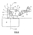
- the force due to resilient means 11 which is transferred to container 2 by means of engaging device 5 is a resistance which decreases during the first stage of insertion (namely between the position shown in Figure 4 and that shown in Figure 5) and a positive force which increases during the second stage of insertion (namely between the position shown in Figure 5 and that shown in Figure 6).
- Resilient means 11 may be a flexible spring, but also other constructional forms are possible such as, for example, a coil spring, a helical spring, a leaf spring, etc.
- engaging device 5 has been shown as rotating in the clockwise direction during insertion, but could be designed symmetrically, achieving the same results.
- inlet 3 has two diametrically opposite pins 6 which are inserted in two respective slots 7 formed on terminal part 4 of the drain circuit
- the same effects of the present invention may be obtained by providing the clothes drier with a second engaging device symmetrical with the first device relative to a plane parallel to the plane defined by first member 9 and passing along the axis X-X.
- the present invention has been described with reference to the axis X-X which, according to a preferred embodiment of the present invention, is horizontal. It is nevertheless possible to realise the teachings of the present invention even if the axis X-X should be oriented differently. Likewise, the present invention is applicable both to front loading clothes driers and to other types of clothes drier, such as, for example, top loading driers.
Landscapes
- Engineering & Computer Science (AREA)
- Textile Engineering (AREA)
- Detail Structures Of Washing Machines And Dryers (AREA)
Priority Applications (2)
| Application Number | Priority Date | Filing Date | Title |
|---|---|---|---|
| DE602006018475T DE602006018475D1 (de) | 2006-10-16 | 2006-10-16 | Wäschetrockner mit verbesserter Eingriffsvorrichtung für den Kondensatsammelbehälter |
| EP06425708A EP1914340B1 (de) | 2006-10-16 | 2006-10-16 | Wäschetrockner mit verbesserter Eingriffsvorrichtung für den Kondensatsammelbehälter |
Applications Claiming Priority (1)
| Application Number | Priority Date | Filing Date | Title |
|---|---|---|---|
| EP06425708A EP1914340B1 (de) | 2006-10-16 | 2006-10-16 | Wäschetrockner mit verbesserter Eingriffsvorrichtung für den Kondensatsammelbehälter |
Publications (2)
| Publication Number | Publication Date |
|---|---|
| EP1914340A1 true EP1914340A1 (de) | 2008-04-23 |
| EP1914340B1 EP1914340B1 (de) | 2010-11-24 |
Family
ID=37836854
Family Applications (1)
| Application Number | Title | Priority Date | Filing Date |
|---|---|---|---|
| EP06425708A Active EP1914340B1 (de) | 2006-10-16 | 2006-10-16 | Wäschetrockner mit verbesserter Eingriffsvorrichtung für den Kondensatsammelbehälter |
Country Status (2)
| Country | Link |
|---|---|
| EP (1) | EP1914340B1 (de) |
| DE (1) | DE602006018475D1 (de) |
Cited By (3)
| Publication number | Priority date | Publication date | Assignee | Title |
|---|---|---|---|---|
| DE102011082253A1 (de) * | 2011-09-07 | 2013-03-07 | BSH Bosch und Siemens Hausgeräte GmbH | Wäschetrocknungsgerät |
| WO2015127986A1 (en) * | 2014-02-28 | 2015-09-03 | Arcelik Anonim Sirketi | Check valve assembly with improved safety for use in a laundry dryer |
| WO2016030239A1 (de) * | 2014-08-29 | 2016-03-03 | BSH Hausgeräte GmbH | Fluidanschlussvorrichtung für ein haushaltsgerät, sowie haushaltsgerät mit einer solchen |
Families Citing this family (1)
| Publication number | Priority date | Publication date | Assignee | Title |
|---|---|---|---|---|
| EP2574696A1 (de) | 2011-09-28 | 2013-04-03 | Electrolux Home Products Corporation N.V. | Wäschetrockner unfassend ein Kondensatspeicherbehälter |
Citations (2)
| Publication number | Priority date | Publication date | Assignee | Title |
|---|---|---|---|---|
| EP0484225A1 (de) * | 1990-11-02 | 1992-05-06 | Ciapem | Wäschetrockner mit einem Kondensatsammelbehälter |
| EP1524359A1 (de) * | 2003-10-16 | 2005-04-20 | Electrolux Home Products Corporation N.V. | Haushaltskondensationswäschetrockner mit Sicherheitskupplung des Kondensatsammelbehälters |
-
2006
- 2006-10-16 EP EP06425708A patent/EP1914340B1/de active Active
- 2006-10-16 DE DE602006018475T patent/DE602006018475D1/de active Active
Patent Citations (2)
| Publication number | Priority date | Publication date | Assignee | Title |
|---|---|---|---|---|
| EP0484225A1 (de) * | 1990-11-02 | 1992-05-06 | Ciapem | Wäschetrockner mit einem Kondensatsammelbehälter |
| EP1524359A1 (de) * | 2003-10-16 | 2005-04-20 | Electrolux Home Products Corporation N.V. | Haushaltskondensationswäschetrockner mit Sicherheitskupplung des Kondensatsammelbehälters |
Cited By (4)
| Publication number | Priority date | Publication date | Assignee | Title |
|---|---|---|---|---|
| DE102011082253A1 (de) * | 2011-09-07 | 2013-03-07 | BSH Bosch und Siemens Hausgeräte GmbH | Wäschetrocknungsgerät |
| EP2568076A1 (de) * | 2011-09-07 | 2013-03-13 | BSH Bosch und Siemens Hausgeräte GmbH | Wäschetrocknungsgerät |
| WO2015127986A1 (en) * | 2014-02-28 | 2015-09-03 | Arcelik Anonim Sirketi | Check valve assembly with improved safety for use in a laundry dryer |
| WO2016030239A1 (de) * | 2014-08-29 | 2016-03-03 | BSH Hausgeräte GmbH | Fluidanschlussvorrichtung für ein haushaltsgerät, sowie haushaltsgerät mit einer solchen |
Also Published As
| Publication number | Publication date |
|---|---|
| DE602006018475D1 (de) | 2011-01-05 |
| EP1914340B1 (de) | 2010-11-24 |
Similar Documents
| Publication | Publication Date | Title |
|---|---|---|
| EP1914340B1 (de) | Wäschetrockner mit verbesserter Eingriffsvorrichtung für den Kondensatsammelbehälter | |
| EP1561853B1 (de) | Vorrichtung zur Vermeidung von Flüssigkeitsüberlauf bei einer Waschmaschine | |
| EP1724387A1 (de) | Verbesserte Vorrichtung zum automatischen Auszug einer Schublade, insbesondere einer Vorratsschublade für ein Haushaltsgerät wie z.B für eine Waschmaschine | |
| EP3045402A1 (de) | Deckel mit verdrehbarer tülleneinheit und behälteranordnung damit | |
| US9995067B2 (en) | Door-lock device | |
| US7355503B2 (en) | Fuse switch | |
| KR20080083903A (ko) | 정수장치 | |
| EP2708637A1 (de) | Filtereinheit für ein Haushaltsgerät | |
| KR20050107206A (ko) | 모니터장치 | |
| EP3000927A1 (de) | Dampferzeuger und wäschebehandlungsvorrichtung | |
| CN105937150B (zh) | 用于衣物处理机的门体组件和具有其的衣物处理机 | |
| BR102015023662B1 (pt) | Aparelho de tratamento de vestuário | |
| CN102733153A (zh) | 洗涤剂容器 | |
| US2803348A (en) | Floor drain cover | |
| US5810217A (en) | Clothespin and clothes-equipment | |
| EP3587661A1 (de) | Trockner | |
| AU2016315378B2 (en) | Head part for forming a liquid treatment apparatus and liquid treatment apparatus | |
| KR930004300Y1 (ko) | 콘센트 안전장치 | |
| KR100325009B1 (ko) | 업라이트 진공청소기의 전원코드권선장치 | |
| EP1524359A1 (de) | Haushaltskondensationswäschetrockner mit Sicherheitskupplung des Kondensatsammelbehälters | |
| KR100667299B1 (ko) | 유량가변형 체크댐퍼 | |
| CN221322684U (zh) | 一种蠕动泵专用管路及蠕动泵 | |
| KR960023555A (ko) | 결속밴드의 자동결속장치 | |
| KR19990016532U (ko) | 급수호스와 급수밸브의 결합구조 | |
| CN104658825A (zh) | 断路器 |
Legal Events
| Date | Code | Title | Description |
|---|---|---|---|
| PUAI | Public reference made under article 153(3) epc to a published international application that has entered the european phase |
Free format text: ORIGINAL CODE: 0009012 |
|
| 17P | Request for examination filed |
Effective date: 20070612 |
|
| AK | Designated contracting states |
Kind code of ref document: A1 Designated state(s): AT BE BG CH CY CZ DE DK EE ES FI FR GB GR HU IE IS IT LI LT LU LV MC NL PL PT RO SE SI SK TR |
|
| AX | Request for extension of the european patent |
Extension state: AL BA HR MK RS |
|
| 17Q | First examination report despatched |
Effective date: 20080724 |
|
| AKX | Designation fees paid |
Designated state(s): DE GB IT |
|
| GRAP | Despatch of communication of intention to grant a patent |
Free format text: ORIGINAL CODE: EPIDOSNIGR1 |
|
| GRAS | Grant fee paid |
Free format text: ORIGINAL CODE: EPIDOSNIGR3 |
|
| GRAA | (expected) grant |
Free format text: ORIGINAL CODE: 0009210 |
|
| AK | Designated contracting states |
Kind code of ref document: B1 Designated state(s): DE GB IT |
|
| REG | Reference to a national code |
Ref country code: GB Ref legal event code: FG4D |
|
| REF | Corresponds to: |
Ref document number: 602006018475 Country of ref document: DE Date of ref document: 20110105 Kind code of ref document: P |
|
| PLBE | No opposition filed within time limit |
Free format text: ORIGINAL CODE: 0009261 |
|
| STAA | Information on the status of an ep patent application or granted ep patent |
Free format text: STATUS: NO OPPOSITION FILED WITHIN TIME LIMIT |
|
| 26N | No opposition filed |
Effective date: 20110825 |
|
| REG | Reference to a national code |
Ref country code: DE Ref legal event code: R097 Ref document number: 602006018475 Country of ref document: DE Effective date: 20110825 |
|
| PGFP | Annual fee paid to national office [announced via postgrant information from national office to epo] |
Ref country code: IT Payment date: 20221027 Year of fee payment: 17 Ref country code: GB Payment date: 20221028 Year of fee payment: 17 Ref country code: DE Payment date: 20221028 Year of fee payment: 17 |
|
| REG | Reference to a national code |
Ref country code: DE Ref legal event code: R119 Ref document number: 602006018475 Country of ref document: DE |
|
| GBPC | Gb: european patent ceased through non-payment of renewal fee |
Effective date: 20231016 |
|
| PG25 | Lapsed in a contracting state [announced via postgrant information from national office to epo] |
Ref country code: GB Free format text: LAPSE BECAUSE OF NON-PAYMENT OF DUE FEES Effective date: 20231016 |
|
| PG25 | Lapsed in a contracting state [announced via postgrant information from national office to epo] |
Ref country code: GB Free format text: LAPSE BECAUSE OF NON-PAYMENT OF DUE FEES Effective date: 20231016 Ref country code: DE Free format text: LAPSE BECAUSE OF NON-PAYMENT OF DUE FEES Effective date: 20240501 |