EP1914008A2 - Verfahren zur Düsenlärmmodellierung, Verfahren zur Düsenlärmanalyse und Verfahren für den Entwurf von Flugzeugen - Google Patents
Verfahren zur Düsenlärmmodellierung, Verfahren zur Düsenlärmanalyse und Verfahren für den Entwurf von Flugzeugen Download PDFInfo
- Publication number
- EP1914008A2 EP1914008A2 EP07118867A EP07118867A EP1914008A2 EP 1914008 A2 EP1914008 A2 EP 1914008A2 EP 07118867 A EP07118867 A EP 07118867A EP 07118867 A EP07118867 A EP 07118867A EP 1914008 A2 EP1914008 A2 EP 1914008A2
- Authority
- EP
- European Patent Office
- Prior art keywords
- jet
- noise
- sound
- jet noise
- sound source
- Prior art date
- Legal status (The legal status is an assumption and is not a legal conclusion. Google has not performed a legal analysis and makes no representation as to the accuracy of the status listed.)
- Granted
Links
Images





Classifications
-
- G—PHYSICS
- G01—MEASURING; TESTING
- G01H—MEASUREMENT OF MECHANICAL VIBRATIONS OR ULTRASONIC, SONIC OR INFRASONIC WAVES
- G01H17/00—Measuring mechanical vibrations or ultrasonic, sonic or infrasonic waves, not provided for in the other groups of this subclass
Definitions
- the present invention relates to a jet noise modeling method of modeling jet noises generated by a jet stream jetted by a jet engine, a jet noise analyzing method, and an aircraft designing method using the jet noise modeling method and the jet noise analyzing method.
- An aircraft design is required to include means for reducing jet noises generated by a jet stream jetted by an engine and uses the shielding effect of an airframe on isolating jet noises. It is necessary to analyze a sound field of jet noises to examine the noise shielding effect of an airframe.
- a jet stream is analyzed by unsteady Navier-Stokes analysis (NS analysis), such as large eddy simulation (LES) or direct Navier-Stokes (DNS) analysis.
- LES large eddy simulation
- DNS direct Navier-Stokes
- the condition of the sound field of jet noises is determined on the basis of a pressure variation estimated from the results of analysis.
- Unsteady NS analysis takes extremely much time. It is very difficult for the ability of a current computer to achieve the analysis of a jet stream jetted by an actual jet engine
- An aerodynamic sound source search system disclosed in JP-A 2005-3368 determines a sound source distribution of aerodynamic sounds generated around an object placed in a field of flow.
- This aerodynamic sound source search system calculates the distribution of velocity vectors in a predetermined finite computational region, and calculates a sound source distribution around the object on the basis of the distribution of velocity vectors, taking into account the influence of vortices outside the computational region.
- This aerodynamic sound source search system sets a predetermined finite computational region as a range for calculating velocity vectors in the field of flow, converts the influence of vortices outside the computational region into the influence of vortices in the computational region, and determines the distribution of dipole sound sources by using an expression developed by combining the Howe's vortex expression and a compact Green function suitable for the shape of the object.
- this aerodynamic sound source search system can determine the distribution of sound sources in the field of flow, this aerodynamic sound source search system cannot be applied to the analysis of a sound field of jet noises.
- a noise environment evaluating system disclosed in JP-A 6-4512 is used for analyzing the levels and distribution of noises generated by a plurality of noise sources.
- This noise environment evaluating system enters data on the arrangement of buildings including walls, and noise sources, produces a sound ray model of sound propagation passages from the data on the arrangement of buildings and the noise sources, determines sound pressure levels at observation points on the sound propagation passages by using an expression expressing sound attenuation in distance, and synthesizes the thus determined sound pressure levels.
- This noise environment evaluating system can simply evaluate the levels and distribution of the current noises by entering data on the arrangement of buildings, and noise sources.
- this noise environment evaluating system can simulate the changes of a noise environment resulting from change in planning conditions without restraint.
- this noise environment evaluating system cannot be applied to the analysis of a sound field of jet noises.
- a noise level predicting method is disclosed in JP-A 1-227023 .
- This noise level predicting method predicts a noise level on the basis of the sound power level of a sound source and distance from the sound source.
- This noise level predicting method calculates the mean sound power level of the sound power levels of a plurality of element planes defined by circumferentially dividing a semispherical plane having its center at the sound source, and calculates the respective ratios of the sound power levels of the element planes to the mean sound power level to use the same as noise directivities for correcting the noise levels.
- This noise level predicting method cannot be applied to the analysis of a sound field of jet noises.
- the present invention is a jet noise source modeling method of creating a jet noise source model, comprising:
- the plurality of point sound sources are set through the analysis of a jet stream, the respective sound strengths of the point sound sources are determined, and the respective phases of noises of the point sound sources are determined by using data on the known noise level.
- a jet noise source model can be practically formed by thus modeling noises of a jet stream in a short period.
- the plurality of point sound sources are determined by quantizing the strength distribution in the jet sound source, and the phases of the point sound sources are determined so as to coincide with a known noise level.
- actual jet noises can be accurately modeled.
- the sound source model thus obtained is suitable for application to the analysis of a sound field around a jet stream, such as the analysis of the noise shielding effect of an object.
- the point sound sources are set along a jet axis of the jet stream.
- the point sound sources are set along the jet axis of a jet stream. Noises of the jet stream are distributed symmetrically with respect to the jet axis and hence an efficient sound source model can be obtained. Any objects are not arranged on the jet axis, and the point sound sources are arranged on the jet axis, Therefore, the sound source model is suitable for analyzing a sound field around the jet stream, such as the analysis of the noise shielding effect of an object.
- the present invention is a jet noise analyzing method of analyzing a sound field around a jet stream by using a jet noise source model created by the jet noise source modeling method mentioned above.
- a sound field of jet noises can be analyzed by using the suitable sound source model obtained by the sound source modeling method. Therefore, the jet noise shielding effect of an object and a sound field around a jet stream can be properly analyzed.
- the present invention is an aircraft designing method of designing an aircraft, wherein an influence of an airframe on a jet noise estimated by the jet noise analyzing method mentioned above is taken into account when the aircraft is designed.
- the effect of an airframe on jet noises can be properly analyzed by the analyzing method and an aircraft can be designed on the basis of the results of the analysis.
- an aircraft capable of effectively shielding the interior thereof from jet noises can be designed.
- the jet noise analyzing method (hereinafter, referred to as "noise analyzing method") in the preferred embodiment includes a sound source modeling method of modeling a jet noise source.
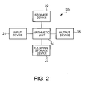
- the noise analyzing method a sound field around a jet stream is analyzed by using a sound source model produced by the sound source modeling method. Therefore, the noise analyzer 20 shown in Fig. 2 is a modeling device for producing a sound source model.
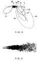
- An aircraft is provided with a jet engine 26 having a nozzle 30 as shown in Fig. 3.
- the jet engine 26 jets a jet stream 31 through the nozzle 30 to generate a thrust.
- Noises generated by the jet engine 26 include a noise generated by a compressor and directionally spreading as indicated by continuous lines 27 in Fig. 3, a noise generated by a turbine and a combustor and directionally spreading as indicated by a broken line 28 in Fig. 3, and a jet noise generated by a jet stream 31 and directionally spreading as indicated by a two-dot chain line 29 in Fig. 3.
- the jet noise generated by the jet stream 31 has a high noise level and spreads in a wide range.
- the reduction of the jet noise is important for the development and designing an aircraft that produces a thrust by jetting a jet stream 31, particularly, for a very-high-speed transport that cruises at a very high speed of, for example, a Mach number M of 1.6.
- the jet engine 26, such as a turbofan engine, used by a very-high-speed transport is an engine having a low bypass ratio.
- the jet noise (mixing noise) is a principal sound source.
- the jet noise may be reduced by an ejector nozzle or a lobed mixer.
- the use of an ejector nozzle or a lobed mixer increases the weight of the aircraft deteriorating the flying performance of the aircraft.
- a jet noise that reaches a part of an airframe on the opposite side of the jet stream with respect to the airframe can be reduced without using additional members which will increase the weight of the aircraft if the jet noise can be shielded by the airframe. Therefore, a noise analyzing method of the present invention is used, for example, to evaluate the noise shielding effect of the airframe.
- the airframe includes main wings, a fuselage, a vertical fin and horizontal stabilizers. The evaluation of the noise shielding effect of the airframe is only an example of uses of the noise analyzing method of the present invention and the noise analyzing method of the present invention is applicable to the analysis of a jet noise for other purposes.
- the noise analyzer 20 shown in Fig. 2 includes an input device 21, a storage device 22, an external storage device 23, an arithmetic unit 24 and an output device 25.
- the noise analyzer 20 is, for example, a super computer.
- the input device 21 is, for example, a keyboard or the like for entering jet information about the jet stream 31, instruction information about instructions requesting modeling and analyzing the sound source of the jet noise, and such.
- the information about the jet stream 31 is, for example, information including jet conditions including the inside diameter of the nozzle 30, the velocity of the jet stream 31 at the exit of the nozzle 30 (hereinafter referred to as “jet exit velocity”), the temperature of the jet stream 31 at the exit of the nozzle 30 (hereinafter referred to as “jet exit temperature”), and the pressure of the jet stream 31 at the exit of the nozzle 30 (hereinafter referred to as “jet exit pressure").
- the storage device 22 is a means, for storing information in a storage medium held in the computer, including, for example, a hard disk drive and a semiconductor memory.
- the external storage device 23 is a means for writing information to detachable recording mediums, such as compact disks (CDs) and digital versatile disks (DVDs), and reading the recorded information from the recording mediums.
- An information holding unit includes the storage device 22 and the external storage device 23. Data necessary for operations specified by an operation program including directions for accomplishing a sound source modeling method and a noise analyzing method of the present invention, and an operation program including directions for accomplishing necessary operations are stored by the unit.
- the information holding unit may temporarily hold information entered by operating the input device 21.
- the arithmetic unit 24 is, for example, a central processing unit (CPU).
- the arithmetic unit 24 reads an operation program including an optimal operation program and an analytical operation program and data from either of the storage device 22 and the external storage device 23 according to directions entered by operating the input device 21. Then, the arithmetic unit 24 executes operations for modeling a jet noise source and noise analysis using jet conditions.
- the output device 25 provides information including results operations of the arithmetic unit 24.
- the output device 25 is, for example, a display.
- the output device 25 may be a printer.
- the external recording device 23 may record information including the jet conditions on a readable recording medium, read the information from the recording medium and enter the information into the arithmetic unit 24. Results of operations of the arithmetic unit 24 may be recorded on a recording medium and sent out by the external recording device 23.
- the external recording device 23 functions also as an information input means and an information output means for providing information including results of operations.
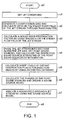
- the arithmetic unit 24 of the noise analyzer 20 carries out a noise analyzing method.
- the input device 21 enters the jet conditions into the arithmetic unit 24 and gives a command causing the arithmetic unit 24 to perform noise analysis.
- a noise analyzing procedure is started in step s0.
- step s1 namely, a condition setting step
- the arithmetic unit 24 receives the input jet conditions and set the same as operational conditions.
- the noise analyzing procedure goes to step s2.
- step s2 namely, data calculating step
- a computation grid is generated, and data on the steady flow field of the jet stream 31 (hereinafter, referred to as "steady flow data") is obtained through RANS analysis (Reynolds-averaged Navier Stokes analysis).
- the steady flow data on the jet stream 31 includes velocity, temperature, pressure, intensity of turbulence, and turbulence damping rate.
- step s3 namely, a propagation factor calculating step
- a propagation factor for a sound wave is calculated by using the steady flow data on the jet stream.
- step s4 namely, a sound source strength calculating step
- the jet stream 31 is divided into sections along the axis L of the jet stream 31 (hereinafter referred to as "jet axis L"), point sound sources are set at the respective middle points of the sections, respectively, and the respective strengths of the point sound sources are calculated.
- the noise analyzing procedure goes to step s5, namely, a noise level determining step.
- step s5 noise levels at observation points far from the jet stream 31 and having the same jet conditions as those determined in step s1 respectively for direction angles ⁇ are retrieved from an existing database.
- each direction angle ⁇ is an angle between a line extending from a point P0 on the jet axis L at the outlet of the nozzle 30 and the jet axis L.
- the direction angle ⁇ is called also an azimuth angle.
- the database is a collection of measured data obtained through experiments.
- step s6 phases are assumed for the point sound sources, and noise levels at the observation points for which the noise levels were determined in step s5.
- the calculated noise levels are compared with the noise levels retrieved from the database, and the phases are optimized such that the calculated noise levels coincide with the noise levels retrieved from the database, respectively.
- a sound source model modeling the jet noise generated by the jet stream by a plurality of point sound sources specified by the sound source strengths and the phases is obtained.
- the noise analyzing procedure goes to step s7.
- the sound source modeling method includes steps s1 to s6.
- the sound source modeling method generates a sound source model.
- step s7 namely, a sound field analyzing step
- a sound field around the jet stream is analyzed using the sound source model obtained in step s6.
- the noise shielding effect of the airframe can be evaluated by analyzing the sound field on an assumption that the airframe is disposed in the sound frame.
- the noise analyzing procedure is ended in step s8 after the completion of the sound field analysis in step s7.
- This embodiment obtains a distribution of point sound sources by quantizing the distribution of sound source strengths, and adjusts the phase angles of the point sound sources so as to coincide with directivities of the point sound sources obtained from the database, such as cold Jet.
- the sound source model thus created is effective in reproducing directivities.
- Jet noise is analyzed by using a sound source model formed by the noise modeling method.
- This embodiment creates a simple shape model simulating an airframe, uses the sound source model and the simple shape model, uses software for analyzing the sound field around the jet stream, and evaluates the noise shielding effect of the airframe to confirm the noise shielding effect of the airframe.
- An airframe having a high noise shielding effect is selected and an airframe having the shape of the selected airframe is designed.
- a designing method according to the present invention designs an airframe having a high noise shielding effect by using the sound source model to design an airframe for an aircraft.
- the method may use a finite element method or a boundary element method.
- This embodiment uses, for example, a fast multipole boundary element method (FMBEM).
- FMBEM fast multipole boundary element method
- the characteristics of jet noise can be accurately indicated by setting a plurality of point sound sources by quantizing a strength distribution by analysis, such as steady RANS analysis, and representing each point sound source by sound source strength and phase characteristic.
- the noise characteristic of jet noise is dependent on whether the jet is a subsonic jet or a supersonic jet, whether or not the noise characteristic is affected by the flying speed of the airframe relative to the surroundings, and whether the jet is a cold jet or a hot jet.
- the modeling method and the analyzing method of the present invention are applicable to the analysis of noises of those various conditions.
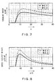
- Fig. 4 is a diagram showing the results of analysis of an unsteady jet flow by way of example.
- the improvement of the computational ability of computers has promoted active studies of a method of directly calculating jet noise generated by the jet stream 31 through the analysis of the unsteady flow of the jet stream 31 as shown in Fig. 4 by LES (large eddy simulation) and DNS (direct numerical simulation).
- LES large eddy simulation
- DNS direct numerical simulation
- the steady RANS (Reynolds averaged Navier-stokes) analysis employed by the present invention that estimates jet noise by using data on steady flow obtained from the results of steady RANS analysis of the jet stream 31 is an analysis based on CFD (computational fluid dynamics).
- CFD analysis is accomplished by steady-state analysis.
- the present invention needs to analyze only an axisymmetric, two-dimensional stream and can greatly reduce operations for numerical calculation.
- Fig. 5 is a sectional view of the jet stream 31 for assistance in explaining an image of estimating jet noise based on steady RANS analysis.
- Propagation of sound waves in the jet stream 31 is modeled by a time-averaged velocity, a time-averaged density and a time-averaged pressure obtained through the steady RANS analysis.
- a typical phenomenon will be explained with reference to an imaginary sound source 40 by way of example.
- a distribution of sound source strengths and temporal and spatial phase relationships are modeled by turbulence statistics obtained by steady RANS analysis.
- the turbulence statistics include a time-averaged turbulence strength and a time-averaged turbulence damping ratio.
- a characteristic phenomenon will be explained with reference to two imaginary sound sources 41 and 42 and an imaginary observation point 43 shown in Fig. 5 by way of example. Interference between sound waves respectively generated by the two imaginary sound sources 41 and 42 in the jet stream 31 occurs at the observation point 43. Those sound waves strengthen or weaken each other depending on the temporal and spatial phase relationships between the imaginary sound sources 41 and 42 at the observation point 43.
- the effect of sound sources in the jet stream 31 on noise level in a far field can be calculated by integrating the two models of propagation of the sound waves, and temporal and spatial relationships of the distribution of sound source strengths.
- the sound source strength S(x, f)[Pa 2 /Hz] at a point x far from the jet stream can be expressed by Expression (1).
- Some variables in Expression (1) are represented by Expressions (2) to (4).
- the variables c l , c ⁇ and A are adjustable constants specific to a turbulence model. Those adjustable constants are adjusted such that data on a turbulence model coincide satisfactorily with known noise data obtained through experiments or the like.
- symbols respectively provided with “ ⁇ ” and “ “” will be represented by symbols respectively followed by “ ⁇ ” (circumflex) and “ “ “ (over line).
- ⁇ circumflex
- ⁇ over line over line
- the position x can be indicated by spherical coordinates (R, ⁇ , ⁇ ), where R is distance from the outlet of the nozzle, ⁇ is angle between a direction and the jet axis L, and ⁇ is angle from a reference plane.
- Sound source strength S(x, f) is the strength of a sound of a frequency f at the position x .
- Sound propagation coefficient p a (x 2 , x, f) is the coefficient of propagation of the sound of the frequency f between the position x and a position x 2 .
- a coordinate system is a cylindrical coordinate system (y, r, ⁇ ) indicating a point by distance r from the y-axis coinciding with the jet axis L on which distance from the exit of the nozzle 30 is measured, and angle ⁇ about the y-axis.
- a position on the cylindrical coordinate system is indicated by coordinates (y, r, ⁇ )
- the sound propagation coefficient p a (x 2 , x, f), and variables u a (x 2 , x, f), v a (x 2 , x, f) and w a (x 2 , x, f) are obtained by numerically solving Expression (5).
- Steps of the noise analyzing procedure will be described again on the basis of Expressions (1) to (4) expressing sound source strength and Expression (5) expressing sound propagation coefficient.
- the input jet conditions are received and set in step s1.
- the jet conditions are shown in Table 1 by way of example.
- Case 1 Case 2 Mach number 0.6 0.8 Static pressure ratio 1 1 Density ratio 1.06 1 Reynolds number 3.72 ⁇ 10 6 5.11 ⁇ 10 6
- Jet conditions for a case 1 and a case 2 are shown in Table 1. Jet exit temperature is not shown.
- Static pressure ratio is the ratio of the static pressure of the jet stream 31 to that of the ambient atmosphere. Mach number is the moving speed of the nozzle 30 relative to the ambient atmosphere.
- Density ratio is the ratio of the density of the jet stream 31 to that of the ambient atmosphere.
- the input device 21 is operated to give those jet conditions to the arithmetic unit 24.
- Fig. 6 is a graph showing a Mach number distribution for the case 1 determined by RANS analysis.
- Fig. 6 shows the Mach number distribution on one side of the jet axis L in a section containing the jet axis L.
- y-coordinates on the cylindrical coordinate system is measured on the horizontal axis
- r-coordinates are measured on the vertical axis.
- the Mach number M is on the order of 0.3 in a whitish region, which corresponds to a mixed layer 34, in Fig. 6.
- the Mach number M is on the order of 0.6 in a comparatively dark region, which corresponds to a core 33, nearer to the y-axis than the mixed layer 34.
- the Mach number M is approximately 0 in a comparatively dark region farther from the y-axis than the mixed region 34. This comparative dark region extends outside the jet stream 31.
- Fig. 7 is a graph showing turbulent energy determined by RANS analysis.
- the turbulent energy at positions on the y-axis, i.e., on the jet axis L, for the case 1 and that for the second case 2 are indicated by a continuous line and a broken line, respectively.
- y-coordinates are measured on the horizontal axis. The y-coordinates are expressed in a unit of the inside diameter D1 of the jet nozzle 30.
- Turbulent energy q/a 0 is measured on the vertical axis. The symbol a 0 indicates sound velocity in the ambient atmosphere.
- turbulent energy increases sharply from a position at a distance from the outlet of the nozzle 30, reaches a peak, and the decreases gradually with distance from the nozzle 30.
- Fig. 8 is a graph showing energy dissipation determined by RANS analysis.
- a continuous line and a broken line indicate modes of dissipation of the turbulent energy at positions on the y-axis coinciding with the jet axis L, for the case 1 and the case 2, respectively.
- y-coordinates are measured on the horizontal axis. The y-coordinates are expressed in a unit of the inside diameter D1 of the jet nozzle 30.
- Turbulent energy dissipation quantity ⁇ D/a 0 indicating a state of dissipation of turbulent energy is measured on the vertical axis in Fig. 8.
- the dissipation of turbulent energy increases sharply from a position at a distance from the outlet of the nozzle 30, reaches a peak and decreases gradually with distance from the outlet of the nozzle 30.
- Fig. 9 is a graph showing the root mean square q of velocity variations and a mean turbulence damping ratio ⁇ .
- y-coordinates are measured on the horizontal axis.
- Root mean square q of velocity variations and mean turbulence damping ratio w are measured on the vertical axis.
- Root mean square q is indicated by a continuous line and a mean turbulence damping ratio w is indicated by a two-dot chain line.
- Data for example, for the case 1 is shown in Fig. 9.
- step s2 RANS analysis is carried out on the basis of the set jet conditions to obtain steady flow data, namely, basic data, as shown in Figs. 6 to 9 by way of example.
- step s3 the propagation characteristic p a (x 2 , x, f) of the propagation of the sound wave from an arbitrary position x 2 in the jet stream 31 to an arbitrary position x outside the jet stream 31 is determined by using the steady flow data.
- the propagation characteristic p a (x 2 , x, f) is obtained by numerically solving Expression (5).
- step s4 the jet stream 31 is divided into sections along the jet axis L of the jet stream 31, namely, the y-axis, at intervals ⁇ y as shown in Fig. 9, and point sound sources are set at the respective middle points of the sections, respectively.
- a plurality of point sound sources O n are arranged at equal intervals on the jet axis L.
- the numbers n are natural numbers assigned to the point sound sources in order of proximity to the nozzle exit.
- Fig. 10 is a diagram of assistance in explaining a method of determining the respective sound source strengths S n of the point sound source On.
- the sound source strength S n of each point sound source O n is calculated using Expression (6) based on Expression (1), and Expressions (2) to (4).
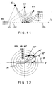
- Fig. 11 is a diagram of assistance in explaining a method of determining the phases ⁇ of the point sound sources O n .
- Fig. 12 is a graph showing sound levels (SPL) included in an existing database by way of example.
- the database may be, for example, the ESDU (Engineering and Science Data Unit).
- a plurality of observation points M m far from the jet stream 31 respectively having different direction angles ⁇ are set as shown in Fig. 11 in step s5.
- the subscript m represents any one of natural numbers assigned to the observation points, respectively, to identify the observation pints.
- Direction angles ⁇ m are identified by subscripts 1, 2, 3, ..., m-1, m, m+1, ... assigned to the direction angles ⁇ in increasing order of direction angles ⁇ , respectively.
- Noise levels L m respectively for the observation points are retrieved from the existing database.
- three observation points M 1 to M 3 are set in the example shown in Fig. 11.
- the direction angles ⁇ at the observation points M 1 , M 2 and M 3 are 30°, 40° and 60°, respectively.
- Noise levels L m at the observation points M m as shown in Fig. 12 are retrieved from the database.
- the noise levels L m at the distant points having the direction angles ⁇ m are retrieved from the existing database in step s5.
- phase s6 phases ⁇ n are determined respectively for the point sound sources On.
- the noise levels at the observation points M m are determined by using sound source strengths S n of the point sound sources On through calculation using Expression (7).
- the calculated noise levels are discriminated from the noise levels L m retrieved from the database by a circumflex and are denoted by L m ⁇ .
- the noise levels retrieved from the existing database are called known noise levels L m and the calculated noise levels calculated using Expression (7) are called calculated noise levels L m ⁇ .
- the phases ⁇ n of the point sound sources On are determined by using, for example, an optimization algorithm such that the sum of squares of the remainders of subtraction of the known noise levels L m from the corresponding calculated noise levels L m ⁇ is reduced to the least possible value.
- the optimization algorithm for determining the phases of the point sound sources On is not a special one and may be any suitable algorithm, such as a gradient method or a genetic algorithm.
- a sound source model represented by the plurality of point sound sources On specified by the noise strengths S n and the phases ⁇ n is created.
- a sound field around the jet stream 31 is analyzed using the thus created sound source model and an airframe model in step s7 to evaluate the noise shielding effect of the airframe.
- An airframe shape having a high noise shielding effect is determined on the basis of the results of analysis made by this analyzing method.
- An airframe capable of reducing jet noise can be designed by using the airframe shape thus determined.
- Fig. 13 is a graph showing sound source strength distributions in an example of a sound source model to be created.
- Fig. 14 is a graph showing phase distributions in an example of a sound source model to be created.
- y-coordinates are measured on the horizontal axis, and sound source strengths S n are measured o the vertical axis.
- y-coordinates are measured on the horizontal axis, and phase angles ⁇ n are measured on the vertical axis.
- the y-coordinates measured on the horizontal axis in Figs. 13 and 14 indicate positions of the point sound sources On on the jet axis L. Values of the y-coordinates are expressed in a unit of the inside diameter D of the nozzle 30.
- Figs. 13 and 14 Data shown in Figs. 13 and 14 are for the case 2 shown in Table 1.
- continuous lines, broken lines and two-dot chain lines indicate variations of sound source strength with distance for frequencies f of 4 kHz, 1 kHz and 250 Hz, respectively.
- the method of the present invention can create a sound source model modeling the point sound sources On by using the sound source strengths S n and the phases ⁇ n .
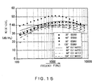
- Fig. 15 is a graph showing an example of a noise level estimated by using the sound source model of the case 1 specified in Table 1
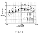
- Fig. 16 is a graph showing an example of a noise level estimated by using the sound source model of the case 2 specified in Table 1.
- Data shown in Figs. 15 and 16 was obtained through estimation using a sound source model created by determining the phase angles ⁇ n such that the calculated sound levels L m ⁇ for the observation point having a direction angle of 90° agree most closely with the corresponding known sound levels L m in step s6 in relation with sound radiation of fine scale turbulence.
- Figs. 15 and 16 frequencies are measured on the horizontal axis, and noise levels are measured on the vertical axis.
- solid circles, solid squares, solid rhombuses, and blank triangles indicate noise levels retrieved from the ESDU, namely, the existing database, for direction angles ⁇ of 30°, 60°, 90° and 120°, respectively.
- solid lines, broken lines, two-dot chain lines and chain lines indicate estimated variations of noise levels estimated through the analysis of an ambient sound field using the created sound source model for direction angles ⁇ of 30°, 60°, 90° and 120°, respectively.
- the estimated sound level for the observation point in the direction of the direction angle ⁇ of 30° is somewhat different from the corresponding noise level retrieved from the existing database, the estimated noise levels agree comparatively satisfactorily with the corresponding noise levels retrieved from the existing database.
- Fig. 17 is a graph showing another example of noise levels estimated by using a created sound source model for the case 1 specified in Table 1
- Fig. 18 is a graph showing another example of noise levels estimated by using the created sound source model for the case 2 specified in Table 1.
- Data shown in Figs. 17 and 18 was obtained through estimation using a sound source model created by determining the phases ⁇ n such that the calculated sound levels L m ⁇ for the observation point having a direction angle of 30° agree most closely with the corresponding known sound levels L m in step s6 in relation with sound radiation of large turbulences structures.
- Figs. 17 and 18 frequencies are measured on the horizontal axis, and noise levels are measured on the vertical axis.
- solid circles, solid squares, solid rhombuses, and blank triangles indicate noise levels retrieved from the ESDU, namely, the existing database, for direction angles ⁇ of 30°, 60°, 90° and 120°, respectively.
- continuous lines, broken lines, two-dot chain lines and chain lines indicate estimated variations of noise levels estimated through the analysis of an ambient sound field using the created sound source model for direction angles ⁇ of 30°, 60°, 90° and 120°, respectively.
- Figs. 17 and 18 continuous lines, broken lines, two-dot chain lines and chain lines indicate estimated variations of noise levels estimated through the analysis of an ambient sound field using the created sound source model for direction angles ⁇ of 30°, 60°, 90° and 120°, respectively.
- the estimated sound levels are approximately equal to the corresponding noise levels retrieved from the existing database regardless of direction angles ⁇ .
- the jet noise as viewed macroscopically has a directional characteristic such that the jet noise is radiated in a direction of a direction angle ⁇ of 30°.
- the sound source model used for estimating the data shown in Figs. 17 and 18 was created by determining the phase in connection with an observation point in a jet noise radiating direction.
- the jet noise radiating direction is a direction in which jet noise of a high radiant intensity is radiated.
- the sound source model created by taking into consideration the directional characteristic of the jet noise in relation with the jet noise radiating direction is an accurate sound source model capable of simulating noises in a wide range of direction angles between 30° and 120°.
- the sound source modeling method and the noise analyzing method of the present invention are applicable to the noise analysis and design of a low-resistance blended wing body airframe, for example, to reduce sonic boom strength by half.
- the sound source modeling method and the noise analyzing method of the present invention are applicable to noise analysis and design for techniques of integrating advanced systems including unmanned aircraft capable of taking off, landing and supersonic flying.
- the sound source modeling method and the noise analyzing method of the present invention can be applied to the analysis of a sound field around a rocket launching pad.
Landscapes
- Physics & Mathematics (AREA)
- General Physics & Mathematics (AREA)
- Measurement Of Mechanical Vibrations Or Ultrasonic Waves (AREA)
Applications Claiming Priority (1)
| Application Number | Priority Date | Filing Date | Title |
|---|---|---|---|
| JP2006286819A JP4184401B2 (ja) | 2006-10-20 | 2006-10-20 | ジェット騒音の音源モデル化方法、ジェット騒音の解析方法および航空機の設計方法 |
Publications (3)
| Publication Number | Publication Date |
|---|---|
| EP1914008A2 true EP1914008A2 (de) | 2008-04-23 |
| EP1914008A3 EP1914008A3 (de) | 2010-06-02 |
| EP1914008B1 EP1914008B1 (de) | 2018-08-08 |
Family
ID=39183907
Family Applications (1)
| Application Number | Title | Priority Date | Filing Date |
|---|---|---|---|
| EP07118867.6A Not-in-force EP1914008B1 (de) | 2006-10-20 | 2007-10-19 | Verfahren zur Düsenlärmmodellierung, Verfahren zur Düsenlärmanalyse und Verfahren für den Entwurf von Flugzeugen |
Country Status (3)
| Country | Link |
|---|---|
| US (1) | US8219363B2 (de) |
| EP (1) | EP1914008B1 (de) |
| JP (1) | JP4184401B2 (de) |
Cited By (2)
| Publication number | Priority date | Publication date | Assignee | Title |
|---|---|---|---|---|
| CN117057207A (zh) * | 2023-10-11 | 2023-11-14 | 北京理工大学 | 一种基于缩比模型的发动机喷管声振响应预测方法 |
| CN119720312A (zh) * | 2024-12-26 | 2025-03-28 | 重庆大学 | 基于声学边界元模型的压缩机机壳噪声预测方法及系统 |
Families Citing this family (12)
| Publication number | Priority date | Publication date | Assignee | Title |
|---|---|---|---|---|
| US8380371B2 (en) * | 2007-03-14 | 2013-02-19 | General Electric Company | Method of generating variable thrust cutback during aircraft departure |
| JP4838829B2 (ja) * | 2008-07-31 | 2011-12-14 | 三菱重工業株式会社 | プロペラによる船体表面の変動圧力推定装置及び方法並びにプログラム |
| US10386212B2 (en) * | 2016-06-22 | 2019-08-20 | Dassault Systemes Simulia Corp. | Flow-induced noise source contribution |
| CN110186556B (zh) * | 2019-06-05 | 2021-04-02 | 上汽大众汽车有限公司 | 一种新能源汽车电机台架试验噪声评价方法 |
| CN111079325B (zh) * | 2019-11-19 | 2022-05-31 | 南京航空航天大学 | 基于代理模型的涡扇发动机喷流噪声实时计算及预测方法 |
| CN112257129B (zh) * | 2020-10-16 | 2024-05-24 | 中国航发沈阳发动机研究所 | 一种噪声源影响范围确定方法 |
| CN113051666B (zh) * | 2021-03-25 | 2022-05-31 | 南京航空航天大学 | 一种旋翼飞行器噪声数字化分析方法及系统 |
| CN113435135B (zh) * | 2021-06-22 | 2022-12-16 | 北京理工大学 | 一种捆绑火箭发动机射流流场及噪声的预估方法 |
| KR102483080B1 (ko) * | 2022-01-07 | 2022-12-30 | 주식회사 이너턴스 | 인공지능을 활용한 항공기 소음 분류 및 추출 방법 |
| CN115541006B (zh) * | 2022-11-29 | 2023-04-07 | 浙江大学 | 基于平面piv的预测指定声源远场流致噪声的方法 |
| CN116220950B (zh) * | 2023-02-24 | 2026-07-17 | 上海宇航系统工程研究所 | 一种发动机喷流声效率影响因子确定方法及装置 |
| CN120517606B (zh) * | 2025-06-06 | 2026-02-03 | 中南大学 | 基于压力梯度线追踪的机身设计方法及系统 |
Family Cites Families (5)
| Publication number | Priority date | Publication date | Assignee | Title |
|---|---|---|---|---|
| JPH01227023A (ja) | 1988-03-07 | 1989-09-11 | Fuji Electric Co Ltd | 騒音レベルの予測方法 |
| DE4030753A1 (de) | 1990-09-28 | 1992-04-02 | Siemens Ag | Verfahren zur berechnung der schallausbreitung in stroemenden medien |
| JPH064512A (ja) | 1992-06-24 | 1994-01-14 | Shimizu Corp | 騒音環境評価システム |
| US6705547B2 (en) * | 2002-02-01 | 2004-03-16 | Luis Manuel Braga Da Costa Campos | Active noise reducing nozzle |
| US7330396B2 (en) | 2004-10-13 | 2008-02-12 | Wayne State University | Farfield analysis of noise sources |
-
2006
- 2006-10-20 JP JP2006286819A patent/JP4184401B2/ja not_active Expired - Fee Related
-
2007
- 2007-10-17 US US11/907,796 patent/US8219363B2/en active Active
- 2007-10-19 EP EP07118867.6A patent/EP1914008B1/de not_active Not-in-force
Non-Patent Citations (1)
| Title |
|---|
| N. GEORGIADIS; J. DEBONIS: "Navier-Stokes analysis methods for turbulent jet flows with application to aircraft exhaust nozzles", PROGRESS IN AEROSPACE SCIENCES, vol. 42, 2006, XP024929379, DOI: doi:10.1016/j.paerosci.2006.12.001 |
Cited By (3)
| Publication number | Priority date | Publication date | Assignee | Title |
|---|---|---|---|---|
| CN117057207A (zh) * | 2023-10-11 | 2023-11-14 | 北京理工大学 | 一种基于缩比模型的发动机喷管声振响应预测方法 |
| CN117057207B (zh) * | 2023-10-11 | 2024-01-30 | 北京理工大学 | 一种基于缩比模型的发动机喷管声振响应预测方法 |
| CN119720312A (zh) * | 2024-12-26 | 2025-03-28 | 重庆大学 | 基于声学边界元模型的压缩机机壳噪声预测方法及系统 |
Also Published As
| Publication number | Publication date |
|---|---|
| US20080103739A1 (en) | 2008-05-01 |
| US8219363B2 (en) | 2012-07-10 |
| EP1914008B1 (de) | 2018-08-08 |
| EP1914008A3 (de) | 2010-06-02 |
| JP2008102095A (ja) | 2008-05-01 |
| JP4184401B2 (ja) | 2008-11-19 |
Similar Documents
| Publication | Publication Date | Title |
|---|---|---|
| EP1914008B1 (de) | Verfahren zur Düsenlärmmodellierung, Verfahren zur Düsenlärmanalyse und Verfahren für den Entwurf von Flugzeugen | |
| Ikeda et al. | Quadrupole corrections for the permeable-surface Ffowcs Williams–Hawkings equation | |
| Zhang et al. | Control of shock/boundary-layer interaction for hypersonic inlets by highly swept microramps | |
| Sasaki et al. | Real-time modelling of wavepackets in turbulent jets | |
| Kanamori et al. | Comparison of simulated sonic boom in stratified atmosphere with flight test measurements | |
| Fiévet et al. | Coalescence in the sound field of a laboratory-scale supersonic jet | |
| Papamoschou | Modelling of noise reduction in complex multistream jets | |
| Stout et al. | Evaluation of numerical predictions of sonic boom level variability due to atmospheric turbulence | |
| US11365704B2 (en) | Directionally targeted jet noise reduction system and method | |
| Spurlock et al. | Cartesian mesh simulations for the third AIAA sonic boom prediction workshop | |
| Khan et al. | Experimental investigation of suddenly expanded flow at sonic and supersonic Mach numbers using semi-circular ribs: a comparative study between experimental, single layer, deep neural network (SLNN and DNN) models | |
| Rallabhandi | Propagation analysis of the 3rd Sonic Boom Prediction Workshop cases using sBOOM | |
| Zhao et al. | Wall pressure fluctuations beneath hypersonic boundary layer over plate | |
| Rašuo et al. | A Study of Aerodynamic Noise in Air Duct Systems with Turning Vanes. | |
| Gao et al. | Numerical analysis and verification of the gas jet from aircraft engines impacting a jet blast deflector | |
| Kakumani et al. | GPU-accelerated numerical study of temperature effects in choked under-expanded supersonic jets | |
| Ashcroft et al. | A computational investigation of the noise radiated by flow-induced cavity oscillations | |
| Blumrich et al. | Variability of focused sonic booms from accelerating supersonic aircraft in consideration of meteorological effects | |
| Johnson et al. | Flow and noise characteristics of under-and over-expanded supersonic rectangular jets | |
| Semiletov et al. | Empiricism-free noise calculation from LES solution based on Goldstein generalized acoustic analogy: volume noise sources and meanflow effects | |
| Brusniak et al. | Phased array measurements of full-scale engine exhaust noise | |
| Gryazev et al. | Robustness of reduced-order jet noise models | |
| Yenigelen et al. | Numerical investigation of a noise reduction strategy for rocket launch vehicles | |
| Loupy et al. | Processing and analysis methods for transonic cavity flow | |
| Miller et al. | Noise Suppression from High-Speed Jet Using Localized Secondary Parallel Injection |
Legal Events
| Date | Code | Title | Description |
|---|---|---|---|
| PUAI | Public reference made under article 153(3) epc to a published international application that has entered the european phase |
Free format text: ORIGINAL CODE: 0009012 |
|
| 17P | Request for examination filed |
Effective date: 20071101 |
|
| AK | Designated contracting states |
Kind code of ref document: A2 Designated state(s): AT BE BG CH CY CZ DE DK EE ES FI FR GB GR HU IE IS IT LI LT LU LV MC MT NL PL PT RO SE SI SK TR |
|
| AX | Request for extension of the european patent |
Extension state: AL BA HR MK RS |
|
| RIC1 | Information provided on ipc code assigned before grant |
Ipc: G01H 17/00 20060101AFI20080325BHEP |
|
| PUAL | Search report despatched |
Free format text: ORIGINAL CODE: 0009013 |
|
| AK | Designated contracting states |
Kind code of ref document: A3 Designated state(s): AT BE BG CH CY CZ DE DK EE ES FI FR GB GR HU IE IS IT LI LT LU LV MC MT NL PL PT RO SE SI SK TR |
|
| AX | Request for extension of the european patent |
Extension state: AL BA HR MK RS |
|
| AKX | Designation fees paid |
Designated state(s): AT BE BG CH CY CZ DE DK EE ES FI FR GB GR HU IE IS IT LI LT LU LV MC MT NL PL PT RO SE SI SK TR |
|
| 17Q | First examination report despatched |
Effective date: 20140711 |
|
| GRAP | Despatch of communication of intention to grant a patent |
Free format text: ORIGINAL CODE: EPIDOSNIGR1 |
|
| INTG | Intention to grant announced |
Effective date: 20180321 |
|
| GRAS | Grant fee paid |
Free format text: ORIGINAL CODE: EPIDOSNIGR3 |
|
| GRAA | (expected) grant |
Free format text: ORIGINAL CODE: 0009210 |
|
| AK | Designated contracting states |
Kind code of ref document: B1 Designated state(s): AT BE BG CH CY CZ DE DK EE ES FI FR GB GR HU IE IS IT LI LT LU LV MC MT NL PL PT RO SE SI SK TR |
|
| REG | Reference to a national code |
Ref country code: GB Ref legal event code: FG4D |
|
| REG | Reference to a national code |
Ref country code: CH Ref legal event code: EP Ref country code: AT Ref legal event code: REF Ref document number: 1027548 Country of ref document: AT Kind code of ref document: T Effective date: 20180815 |
|
| REG | Reference to a national code |
Ref country code: IE Ref legal event code: FG4D |
|
| REG | Reference to a national code |
Ref country code: DE Ref legal event code: R096 Ref document number: 602007055632 Country of ref document: DE |
|
| REG | Reference to a national code |
Ref country code: FR Ref legal event code: PLFP Year of fee payment: 12 |
|
| REG | Reference to a national code |
Ref country code: NL Ref legal event code: MP Effective date: 20180808 |
|
| REG | Reference to a national code |
Ref country code: LT Ref legal event code: MG4D |
|
| REG | Reference to a national code |
Ref country code: AT Ref legal event code: MK05 Ref document number: 1027548 Country of ref document: AT Kind code of ref document: T Effective date: 20180808 |
|
| PG25 | Lapsed in a contracting state [announced via postgrant information from national office to epo] |
Ref country code: LT Free format text: LAPSE BECAUSE OF FAILURE TO SUBMIT A TRANSLATION OF THE DESCRIPTION OR TO PAY THE FEE WITHIN THE PRESCRIBED TIME-LIMIT Effective date: 20180808 Ref country code: PL Free format text: LAPSE BECAUSE OF FAILURE TO SUBMIT A TRANSLATION OF THE DESCRIPTION OR TO PAY THE FEE WITHIN THE PRESCRIBED TIME-LIMIT Effective date: 20180808 Ref country code: IS Free format text: LAPSE BECAUSE OF FAILURE TO SUBMIT A TRANSLATION OF THE DESCRIPTION OR TO PAY THE FEE WITHIN THE PRESCRIBED TIME-LIMIT Effective date: 20181208 Ref country code: BG Free format text: LAPSE BECAUSE OF FAILURE TO SUBMIT A TRANSLATION OF THE DESCRIPTION OR TO PAY THE FEE WITHIN THE PRESCRIBED TIME-LIMIT Effective date: 20181108 Ref country code: NL Free format text: LAPSE BECAUSE OF FAILURE TO SUBMIT A TRANSLATION OF THE DESCRIPTION OR TO PAY THE FEE WITHIN THE PRESCRIBED TIME-LIMIT Effective date: 20180808 Ref country code: AT Free format text: LAPSE BECAUSE OF FAILURE TO SUBMIT A TRANSLATION OF THE DESCRIPTION OR TO PAY THE FEE WITHIN THE PRESCRIBED TIME-LIMIT Effective date: 20180808 Ref country code: GR Free format text: LAPSE BECAUSE OF FAILURE TO SUBMIT A TRANSLATION OF THE DESCRIPTION OR TO PAY THE FEE WITHIN THE PRESCRIBED TIME-LIMIT Effective date: 20181109 Ref country code: FI Free format text: LAPSE BECAUSE OF FAILURE TO SUBMIT A TRANSLATION OF THE DESCRIPTION OR TO PAY THE FEE WITHIN THE PRESCRIBED TIME-LIMIT Effective date: 20180808 Ref country code: SE Free format text: LAPSE BECAUSE OF FAILURE TO SUBMIT A TRANSLATION OF THE DESCRIPTION OR TO PAY THE FEE WITHIN THE PRESCRIBED TIME-LIMIT Effective date: 20180808 |
|
| PG25 | Lapsed in a contracting state [announced via postgrant information from national office to epo] |
Ref country code: LV Free format text: LAPSE BECAUSE OF FAILURE TO SUBMIT A TRANSLATION OF THE DESCRIPTION OR TO PAY THE FEE WITHIN THE PRESCRIBED TIME-LIMIT Effective date: 20180808 Ref country code: ES Free format text: LAPSE BECAUSE OF FAILURE TO SUBMIT A TRANSLATION OF THE DESCRIPTION OR TO PAY THE FEE WITHIN THE PRESCRIBED TIME-LIMIT Effective date: 20180808 |
|
| PG25 | Lapsed in a contracting state [announced via postgrant information from national office to epo] |
Ref country code: CZ Free format text: LAPSE BECAUSE OF FAILURE TO SUBMIT A TRANSLATION OF THE DESCRIPTION OR TO PAY THE FEE WITHIN THE PRESCRIBED TIME-LIMIT Effective date: 20180808 Ref country code: IT Free format text: LAPSE BECAUSE OF FAILURE TO SUBMIT A TRANSLATION OF THE DESCRIPTION OR TO PAY THE FEE WITHIN THE PRESCRIBED TIME-LIMIT Effective date: 20180808 Ref country code: EE Free format text: LAPSE BECAUSE OF FAILURE TO SUBMIT A TRANSLATION OF THE DESCRIPTION OR TO PAY THE FEE WITHIN THE PRESCRIBED TIME-LIMIT Effective date: 20180808 Ref country code: RO Free format text: LAPSE BECAUSE OF FAILURE TO SUBMIT A TRANSLATION OF THE DESCRIPTION OR TO PAY THE FEE WITHIN THE PRESCRIBED TIME-LIMIT Effective date: 20180808 |
|
| REG | Reference to a national code |
Ref country code: DE Ref legal event code: R119 Ref document number: 602007055632 Country of ref document: DE |
|
| PG25 | Lapsed in a contracting state [announced via postgrant information from national office to epo] |
Ref country code: DK Free format text: LAPSE BECAUSE OF FAILURE TO SUBMIT A TRANSLATION OF THE DESCRIPTION OR TO PAY THE FEE WITHIN THE PRESCRIBED TIME-LIMIT Effective date: 20180808 Ref country code: SK Free format text: LAPSE BECAUSE OF FAILURE TO SUBMIT A TRANSLATION OF THE DESCRIPTION OR TO PAY THE FEE WITHIN THE PRESCRIBED TIME-LIMIT Effective date: 20180808 |
|
| REG | Reference to a national code |
Ref country code: CH Ref legal event code: PL |
|
| PLBE | No opposition filed within time limit |
Free format text: ORIGINAL CODE: 0009261 |
|
| STAA | Information on the status of an ep patent application or granted ep patent |
Free format text: STATUS: NO OPPOSITION FILED WITHIN TIME LIMIT |
|
| REG | Reference to a national code |
Ref country code: BE Ref legal event code: MM Effective date: 20181031 |
|
| PG25 | Lapsed in a contracting state [announced via postgrant information from national office to epo] |
Ref country code: LU Free format text: LAPSE BECAUSE OF NON-PAYMENT OF DUE FEES Effective date: 20181019 Ref country code: MC Free format text: LAPSE BECAUSE OF FAILURE TO SUBMIT A TRANSLATION OF THE DESCRIPTION OR TO PAY THE FEE WITHIN THE PRESCRIBED TIME-LIMIT Effective date: 20180808 |
|
| 26N | No opposition filed |
Effective date: 20190509 |
|
| REG | Reference to a national code |
Ref country code: IE Ref legal event code: MM4A |
|
| PG25 | Lapsed in a contracting state [announced via postgrant information from national office to epo] |
Ref country code: DE Free format text: LAPSE BECAUSE OF NON-PAYMENT OF DUE FEES Effective date: 20190501 |
|
| PG25 | Lapsed in a contracting state [announced via postgrant information from national office to epo] |
Ref country code: BE Free format text: LAPSE BECAUSE OF NON-PAYMENT OF DUE FEES Effective date: 20181031 Ref country code: CH Free format text: LAPSE BECAUSE OF NON-PAYMENT OF DUE FEES Effective date: 20181031 Ref country code: LI Free format text: LAPSE BECAUSE OF NON-PAYMENT OF DUE FEES Effective date: 20181031 Ref country code: SI Free format text: LAPSE BECAUSE OF FAILURE TO SUBMIT A TRANSLATION OF THE DESCRIPTION OR TO PAY THE FEE WITHIN THE PRESCRIBED TIME-LIMIT Effective date: 20180808 |
|
| PG25 | Lapsed in a contracting state [announced via postgrant information from national office to epo] |
Ref country code: IE Free format text: LAPSE BECAUSE OF NON-PAYMENT OF DUE FEES Effective date: 20181019 |
|
| PG25 | Lapsed in a contracting state [announced via postgrant information from national office to epo] |
Ref country code: MT Free format text: LAPSE BECAUSE OF NON-PAYMENT OF DUE FEES Effective date: 20181019 |
|
| PG25 | Lapsed in a contracting state [announced via postgrant information from national office to epo] |
Ref country code: TR Free format text: LAPSE BECAUSE OF FAILURE TO SUBMIT A TRANSLATION OF THE DESCRIPTION OR TO PAY THE FEE WITHIN THE PRESCRIBED TIME-LIMIT Effective date: 20180808 |
|
| PG25 | Lapsed in a contracting state [announced via postgrant information from national office to epo] |
Ref country code: PT Free format text: LAPSE BECAUSE OF FAILURE TO SUBMIT A TRANSLATION OF THE DESCRIPTION OR TO PAY THE FEE WITHIN THE PRESCRIBED TIME-LIMIT Effective date: 20180808 |
|
| PG25 | Lapsed in a contracting state [announced via postgrant information from national office to epo] |
Ref country code: HU Free format text: LAPSE BECAUSE OF FAILURE TO SUBMIT A TRANSLATION OF THE DESCRIPTION OR TO PAY THE FEE WITHIN THE PRESCRIBED TIME-LIMIT; INVALID AB INITIO Effective date: 20071019 Ref country code: CY Free format text: LAPSE BECAUSE OF FAILURE TO SUBMIT A TRANSLATION OF THE DESCRIPTION OR TO PAY THE FEE WITHIN THE PRESCRIBED TIME-LIMIT Effective date: 20180808 |
|
| PGFP | Annual fee paid to national office [announced via postgrant information from national office to epo] |
Ref country code: GB Payment date: 20230831 Year of fee payment: 17 |
|
| PGFP | Annual fee paid to national office [announced via postgrant information from national office to epo] |
Ref country code: FR Payment date: 20230911 Year of fee payment: 17 |
|
| GBPC | Gb: european patent ceased through non-payment of renewal fee |
Effective date: 20241019 |
|
| PG25 | Lapsed in a contracting state [announced via postgrant information from national office to epo] |
Ref country code: GB Free format text: LAPSE BECAUSE OF NON-PAYMENT OF DUE FEES Effective date: 20241019 |
|
| PG25 | Lapsed in a contracting state [announced via postgrant information from national office to epo] |
Ref country code: FR Free format text: LAPSE BECAUSE OF NON-PAYMENT OF DUE FEES Effective date: 20241031 |