EP1913680B1 - Elektrische stromquelle, insbesondere schweissstromquelle - Google Patents
Elektrische stromquelle, insbesondere schweissstromquelle Download PDFInfo
- Publication number
- EP1913680B1 EP1913680B1 EP06778078A EP06778078A EP1913680B1 EP 1913680 B1 EP1913680 B1 EP 1913680B1 EP 06778078 A EP06778078 A EP 06778078A EP 06778078 A EP06778078 A EP 06778078A EP 1913680 B1 EP1913680 B1 EP 1913680B1
- Authority
- EP
- European Patent Office
- Prior art keywords
- current source
- series
- resonant
- parallel
- transformers
- Prior art date
- Legal status (The legal status is an assumption and is not a legal conclusion. Google has not performed a legal analysis and makes no representation as to the accuracy of the status listed.)
- Active
Links
Images




Classifications
-
- H—ELECTRICITY
- H02—GENERATION; CONVERSION OR DISTRIBUTION OF ELECTRIC POWER
- H02M—APPARATUS FOR CONVERSION BETWEEN AC AND AC, BETWEEN AC AND DC, OR BETWEEN DC AND DC, AND FOR USE WITH MAINS OR SIMILAR POWER SUPPLY SYSTEMS; CONVERSION OF DC OR AC INPUT POWER INTO SURGE OUTPUT POWER; CONTROL OR REGULATION THEREOF
- H02M3/00—Conversion of DC power input into DC power output
- H02M3/22—Conversion of DC power input into DC power output with intermediate conversion into AC
- H02M3/24—Conversion of DC power input into DC power output with intermediate conversion into AC by static converters
- H02M3/28—Conversion of DC power input into DC power output with intermediate conversion into AC by static converters using discharge tubes with control electrode or semiconductor devices with control electrode to produce the intermediate AC
- H02M3/325—Conversion of DC power input into DC power output with intermediate conversion into AC by static converters using discharge tubes with control electrode or semiconductor devices with control electrode to produce the intermediate AC using devices of a triode or a transistor type requiring continuous application of a control signal
- H02M3/335—Conversion of DC power input into DC power output with intermediate conversion into AC by static converters using discharge tubes with control electrode or semiconductor devices with control electrode to produce the intermediate AC using devices of a triode or a transistor type requiring continuous application of a control signal using semiconductor devices only
-
- H—ELECTRICITY
- H02—GENERATION; CONVERSION OR DISTRIBUTION OF ELECTRIC POWER
- H02M—APPARATUS FOR CONVERSION BETWEEN AC AND AC, BETWEEN AC AND DC, OR BETWEEN DC AND DC, AND FOR USE WITH MAINS OR SIMILAR POWER SUPPLY SYSTEMS; CONVERSION OF DC OR AC INPUT POWER INTO SURGE OUTPUT POWER; CONTROL OR REGULATION THEREOF
- H02M1/00—Details of apparatus for conversion
- H02M1/0067—Converter structures employing plural converter units, other than for parallel operation of the units on a single load
- H02M1/0077—Plural converter units whose outputs are connected in series
-
- Y—GENERAL TAGGING OF NEW TECHNOLOGICAL DEVELOPMENTS; GENERAL TAGGING OF CROSS-SECTIONAL TECHNOLOGIES SPANNING OVER SEVERAL SECTIONS OF THE IPC; TECHNICAL SUBJECTS COVERED BY FORMER USPC CROSS-REFERENCE ART COLLECTIONS [XRACs] AND DIGESTS
- Y02—TECHNOLOGIES OR APPLICATIONS FOR MITIGATION OR ADAPTATION AGAINST CLIMATE CHANGE
- Y02B—CLIMATE CHANGE MITIGATION TECHNOLOGIES RELATED TO BUILDINGS, e.g. HOUSING, HOUSE APPLIANCES OR RELATED END-USER APPLICATIONS
- Y02B70/00—Technologies for an efficient end-user side electric power management and consumption
- Y02B70/10—Technologies improving the efficiency by using switched-mode power supplies [SMPS], i.e. efficient power electronics conversion e.g. power factor correction or reduction of losses in power supplies or efficient standby modes
-
- Y—GENERAL TAGGING OF NEW TECHNOLOGICAL DEVELOPMENTS; GENERAL TAGGING OF CROSS-SECTIONAL TECHNOLOGIES SPANNING OVER SEVERAL SECTIONS OF THE IPC; TECHNICAL SUBJECTS COVERED BY FORMER USPC CROSS-REFERENCE ART COLLECTIONS [XRACs] AND DIGESTS
- Y02—TECHNOLOGIES OR APPLICATIONS FOR MITIGATION OR ADAPTATION AGAINST CLIMATE CHANGE
- Y02P—CLIMATE CHANGE MITIGATION TECHNOLOGIES IN THE PRODUCTION OR PROCESSING OF GOODS
- Y02P80/00—Climate change mitigation technologies for sector-wide applications
- Y02P80/10—Efficient use of energy, e.g. using compressed air or pressurized fluid as energy carrier
Definitions
- the invention relates to an electrical power source, in particular welding power source, having the features of the preamble of claim 1.
- the EP 1 251 991 B1 shows a welding power source with a resonant converter having an input side connected to a DC power bridge circuit.
- the bridge circuit is designed as a full bridge. On the output side, the bridge circuit is connected to a resonant circuit whose outputs are connected directly to the load circuit.
- the transmitted power depends very much on the design of the components of the resonant circuit. Due to the unavoidable scattering of the components must therefore be expected in parallel connection of resonant converters with a very different power transmission of the parallel converter, if all parallel converters are modulated in the same way. This is equivalent to the fact that without special measures a uniform distribution of power to several parallel resonant converter can only be achieved with individual control of the parallel converter. This is synonymous with an undesirably high tax expense.
- each resonant converter a separate output-side rectifier would have to be assigned on the input side of the load circuit in order to avoid AC losses.
- JP 10216936 is an electric welding power source known in which two resonance converters are connected in parallel.
- Each resonant converter has a bridge circuit connected on the input side to an electrical DC power source and a resonant circuit with a transformer arranged on the output side of the bridge circuit.
- the secondary side of the transformer is connected to an output-side load circuit.
- the secondary sides of the transformers of the resonant circuits are electrically connected in series.
- the invention is based on the general idea of providing a secondary side of the transformers common to the parallel resonant converters so that the parallel resonant circuits are "rigidly” coupled together and the parallel resonant converters are practically synchronized with respect to their resonant oscillations.
- the resonant converters on the secondary side of the transformers associated with a common parallel capacitance, so that the resonant converter work in parallel as a parallel resonant converter or as a series-parallel resonant converter.
- the common parallel capacitance has a frequency-determining effect on all resonant converters, so that the resonant oscillations of the converters are synchronized particularly strongly.
- a single rectifier can be provided on the secondary side of the transformers for the parallel resonant converter.
- the series connection of the secondary sides of the transformers can be formed according to a preferred embodiment so that each complete secondary sides are electrically connected in series.
- each secondary side portion of the transformer of a resonant converter is electrically directly in series with a secondary side portion of the transformer of another resonant converter.
- Fig. 1 3 shows a circuit diagram of a first embodiment of the invention with two parallel resonant converters which are connected in parallel to a DC electrical source on the input side,
- Fig. 2 one opposite Fig. 1 modified embodiment in which the parallel resonant converters are connected on the input side in series with the electrical DC power source,
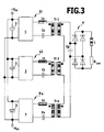
- FIG. 3 one of the Fig. 1 corresponding arrangement with more than two parallel resonant converters
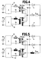
- Fig. 4 an embodiment in which the secondary sides of the output-side transformers of the resonant converter have center taps
- Fig. 5 a modification of the in Fig. 4 illustrated circuit
- Fig. 6 a first variant with half-bridge circuit
- Fig. 7 another variant with half-bridge circuit
- Fig. 8 a modification of the embodiment according to Fig. 2 .
- Fig. 1 are connected to the output contacts + V DC and - V DC two resonant converters 11 and 12 connected in parallel to each other.
- Each resonant converter 11 and 12 has on the input side a clocked bridge circuit 1 or 2, which converts the input side electrical DC voltage of the DC power source into an output side electrical AC voltage whose frequency corresponds to the clock frequency.
- the inputs of the two bridge circuits 1 and 2 are connected to each other via capacitors 3 with high capacity, for example via electrolytic capacitors.
- series circuits are arranged between the outputs of the bridge circuits 1 and 2, which comprise an inductance Ls, the primary side of a high-frequency transformer Tr1 or Tr2 and a series capacitance Cs.
- the secondary sides of the transformers Tr1 and Tr2 are electrically connected in series with each other and connected in parallel with a parallel capacitance Cp common to both resonant converters 11 and 12.
- the inductance Ls can also be formed by the integrated leakage inductance of the transformer Tr1 or Tr2.
- Parallel to the parallel capacitance Cp is arranged for both resonance converters 11 and 12, with respect to the transformers Tr1 and Tr2 secondary rectifier circuit 4, which feeds an electrical load circuit, for example, a welding process, the Fig. 1 as an electrical equivalent circuit diagram, that is shown with a series circuit of an inductance L and a load resistor R last .
- the resonance converters 11 and 12 are strongly coupled to each other and vibrationally synchronized with each other, because of the series-connected secondary windings of the transformers Tr1 and Tr2, the parallel resonant capacitor Cp acts on the individual resonant circuits on the input side of the transformers Tr1 and Tr2.
- the parallel capacitor Cp is connected according to the invention parallel to the series-connected secondary sides of the transformers Tr1 and Tr2, it is a determining component for the resonant frequency for both resonant converters 11 and 12.
- the parallel capacitor Cp is connected according to the invention parallel to the series-connected secondary sides of the transformers Tr1 and Tr2
- it is a determining component for the resonant frequency for both resonant converters 11 and 12.
- the resonance converters 11 and 12 are each designed as a series-parallel resonance converter, wherein each converter 11 or 12 has the capacitance Cs in series with its inductance Ls and the parallel capacitance Cp common to both converters.
- the converter 11 and 12 may be formed as a parallel resonant converter. Then the capacities Cs are eliminated.
- the common parallel capacitance Cp can be omitted if the series capacitances Cs are present and the resonant converters are accordingly designed as series resonant converters. Only the secondary side of the transformers Tr1 and Tr2 common to the converters ensures sufficiently synchronous oscillation of the converters with synchronous clocking of the bridge circuits 1 and 2.
- the common parallel capacitance Cp additionally improves the synchronization of the oscillations.
- Fig. 2 differs from the arrangement Fig. 1 merely in that the inputs of the bridge circuits 1 and 2 of the converters 11 and 12 are connected in series between the contacts + V DC and - V DC of the DC power source. Such a circuit is useful when the electrical input voltage to the bridge circuits 1 and 2 should be half as large as the electrical voltage between the contacts of the DC power source.
- Fig. 3 shows that more than two resonant converters 11 and 12 to Kn work in parallel with a common secondary side of the transformers Tr1 to Trn and common parallel capacitance Cp and with a common rectifier 4 on the input side of the load circuit L, R can be connected last .
- the associated bridge circuits 1 and 2 to n can, as in Fig. 3 is shown, the input side to be connected in parallel, analogous to the arrangement in Fig. 1 ,
- the series capacities Cs may also be omitted.
- the common parallel capacitance Cp could be omitted in principle, because only the series connection of the secondary sides of the transformers Tr1 to Trn causes a sufficient synchronization of the converters 11, 12 to K n .
- the parallel capacity is advantageous.
- the 4 and 5 show two exemplary embodiments in which the secondary sides of the transformers Tr1 and Tr2 are provided with center taps. Accordingly, the secondary-side partial windings of the transformers Tr1 and Tr2 can be connected in series in different ways.
- Fig. 6 shows now that the bridge circuits 1 and 2 can also be designed as half-bridges, wherein the series capacitance Cs is formed by two capacitors with the capacitances Cs / 2.
- the resonance converters 11 and 12 in turn form series-parallel converters.
- the parallel capacitance Cp may possibly be omitted since the series connection of the secondary sides of the transformers Tr1 and Tr2 ensures a sufficient synchronization of the resonance converters 11 and 12 with synchronous clocking of the half bridges 1 and 2.
- the arrangement of the parallel capacitance Cp is extremely advantageous in view of a particularly high degree of synchronization.
- the bridge circuits 1 and 2 can be connected in the same way in parallel or in series with an electrical DC voltage source, as shown in the Fig. 1 and 2 is shown by way of example.
- the resonance converter 11 and 12 of Fig. 7 also individually, independently can be used from each other, Umschalt- or Umsteckan extract must be provided, which allow the in Fig. 7 each connected to the parallel resonant converter connection of the primary side of the transformer Tr1 of the resonant converter 11 and the transformer Tr2 of the resonant converter 12 in the in Fig. 6 shown connected between two connected in series between the inputs of the respective bridge circuit 1 and 2 capacitors.
- Fig. 8 shows in contrast to Fig. 2 , which represents a circuit with two modules or bridge circuits 1,2, a corresponding circuit with n modules / bridge circuits.
Landscapes
- Engineering & Computer Science (AREA)
- Power Engineering (AREA)
- Dc-Dc Converters (AREA)
- Lining Or Joining Of Plastics Or The Like (AREA)
- Resistance Welding (AREA)
- Inverter Devices (AREA)
- Supply And Distribution Of Alternating Current (AREA)
- Electrical Discharge Machining, Electrochemical Machining, And Combined Machining (AREA)
Description
- Die Erfindung bezieht sich auf einer elektrische Stromquelle, insbesondere Schweißstromquelle, mit den Merkmalen des Oberbegriffes von Patentanspruch 1.
- Die
EP 1 251 991 B1 zeigt eine Schweißstromquelle mit einem Resonanzkonverter, der eine eingangsseitig mit einer Gleichstromquelle verbundene Brückenschaltung aufweist. Die Brückenschaltung ist als Vollbrücke ausgebildet. Ausgangsseitig ist die Brückenschaltung mit einem Resonanzkreis verbunden, dessen Ausgänge direkt mit dem Lastkreis verbunden sind. - Eine weitere Stromquelle mit Resonanzkonverter und als Halbbrücke ausgebildeter Brückenschaltung und ohne Transformator ist aus der
DE 44 11 227 A1 bekannt. - Es ist grundsätzlich bekannt, Konverter parallel zu schalten, wenn im Lastkreis eine hohe Leistung benötigt wird. Dies ist bei Verwendung sog. Durchfluss- bzw. Sperrkonverter ohne weiteres möglich, weil diese Konverter eine taktsynchrone Pulsweitenmodulation zulassen, ohne dass sich eine nennenswerte ungleiche Leistungsverteilung auf die Konverter ergeben kann. Die von jedem Konverter übertragene Leistung ist praktisch nur von der jeweiligen Pulsweite der Pulsweitenmodulation abhängig.
- Bei Resonanzkonvertern hängt dagegen die übertragene Leistung sehr stark von der Bemessung der Bauelemente des Resonanzkreises ab. Aufgrund der unvermeidlichen Streuung der Bauelemente muss deshalb bei Parallelschaltung von Resonanzkonvertern mit einer sehr unterschiedlichen Leistungsübertragung der parallel geschalteten Konverter gerechnet werden, wenn alle parallelen Konverter in gleicher Weise moduliert werden. Dies ist gleichbedeutend damit, dass ohne besondere Maßnahmen eine gleichmäßige Verteilung der Leistung auf mehrere parallele Resonanzkonverter nur mit individueller Steuerung der parallelen Konverter erreichbar ist. Dies ist gleichbedeutend mit einem unerwünscht hohen Steueraufwand. Hinzu kommt, dass jedem Resonanzkonverter ein gesonderter ausgangsseitiger Gleichrichter eingangsseitig des Laststromkreises zugeordnet sein müsste, um Wechselstromverluste zu vermeiden.
- Aus der japanischen Veröffentlichung
JP 10216936 - Es ist Aufgabe der Erfindung, bei einer Stromquelle der eingangs angegebenen Art einerseits hohe Leistungen im Lastkreis zu ermöglichen und andererseits den notwendigen Schaltungs- und Steueraufwand äußerst gering zu halten.
- Diese Aufgabe wird erfindungsgemäß durch eine elektrische Stromquelle mit den Merkmalen von Patentanspruch 1 gelöst.
- Die Erfindung beruht auf dem allgemeinen Gedanken, eine für die parallelen Resonanzkonverter gemeinsame Sekundärseite der Transformatoren vorzusehen, so dass die parallelen Resonanzkreise "starr" miteinander gekoppelt werden und die parallelen Resonanzkonverter bezüglich ihrer Resonanzschwingungen praktisch synchronisiert sind. Hierzu ist den Resonanzkonvertern auf der Sekundärseite der Transformatoren eine gemeinsame Parallelkapazität zugeordnet, so dass die Resonanzkonverter parallel als Parallelresonanzkonverter oder als Serienparallelresonanzkonverter arbeiten. Die gemeinsame Parallelkapazität wirkt für alle Resonanzkonverter frequenzbestimmend, so dass die Resonanzschwingungen der Konverter besonders stark synchronisiert werden.
- Damit ist es ohne weiteres möglich, die Brückenschaltungen der parallel geschalteten Resonanzkonverter völlig synchron zu takten, mit der Folge, dass auch bei einer Vielzahl paralleler Resonanzkonverter nur ein gleicher Steuerungsaufwand wie bei einem einzigen Resonanzkonverter erforderlich wird.
- Desweiteren kann für die parallelen Resonanzkonverter ein einziger Gleichrichter auf der Sekundärseite der Transformatoren vorgesehen werden.
- Die Reihenschaltung der Sekundärseiten der Transformatoren kann gemäß einer bevorzugten Ausführungsform so ausgebildet sein, dass jeweils vollständige Sekundärseiten elektrisch in Reihe geschaltet sind.
- Statt dessen ist es gemäß einer weiteren bevorzugten Ausführungsform der Erfindung auch möglich, an den genannten Transformatoren sekundärseitige Mittelpunktanzapfungen vorzusehen und die Reihenschaltung so auszubilden, dass jeweils ein Sekundärseitenteil des Transformators eines Resonanzkonverters elektrisch direkt in Reihe liegt zu einem Sekundärseitenteil des Transformators eines anderen Resonanzkonverters.
- Im übrigen wird hinsichtlich bevorzugter Merkmale die Erfindung auf die Ansprüche sowie die nachfolgende Erläuterung der Zeichnung verwiesen, anhand der besonders bevorzugte Ausführungsformen der Erfindung näher beschrieben werden.
- Schutz wird nicht nur für ausdrücklich dargestellte oder angegebene Merkmalskombinationen sondern prinzipiell auch für beliebige Unterkombinationen dieser Merkmale beansprucht.
- In der Zeichnung zeigt
-
Fig. 1 ein Schaltbild einer ersten Ausführungsform der Erfindung mit zwei parallelen Resonanzkonvertern, die eingangsseitig parallel mit einer elektrischen Gleichspannungsquelle verbunden sind, -
Fig. 2 eine gegenüberFig. 1 abgewandelte Ausführungsform, bei der die parallelen Resonanzkonverter eingangsseitig in Reihe mit der elektrischen Gleichstromquelle verbunden sind, -
Fig. 3 eine derFig. 1 entsprechende Anordnung mit mehr als zwei parallelen Resonanzkonvertern, -
Fig. 4 eine Ausführungsform, bei der die Sekundärseiten der ausgangsseitigen Transformatoren der Resonanzkonverter Mittelpunktanzapfungen aufweisen, -
Fig. 5 eine Abwandlung der inFig. 4 dargestellten Schaltung -
Fig. 6 eine erste Variante mit Halbbrückenschaltung, -
Fig. 7 eine weitere Variante mit Halbbrückenschaltung und -
Fig. 8 eine Abwandlung der Ausführung nachFig. 2 . - Gemäß
Fig. 1 sind mit den Ausgangskontakten + VDC und - VDC zwei Resonanzkonverter 11 und 12 in Parallelschaltung zueinander verbunden. Jeder Resonanzkonverter 11 und 12 besitzt eingangsseitig eine getaktete Brückschaltung 1 bzw. 2, die die eingangsseitige elektrische Gleichspannung der Gleichstromquelle in eine ausgangsseitige elektrische Wechselspannung umsetzt, deren Frequenz der Taktfrequenz entspricht. Um zu vermeiden, dass elektrische Wechselströme bzw. -spannungen auf die Eingangsseite der Brückenschaltungen 1 und 2 zurückgekoppelt werden können, sind die Eingänge der beiden Brückenschaltungen 1 und 2 miteinander jeweils über Kondensatoren 3 mit hoher Kapazität, beispielsweise über Elektrolyt-Kondensatoren, miteinander verbunden. - Zwischen den Ausgängen der Brückenschaltungen 1 und 2 sind jeweils Reihenschaltungen angeordnet, die eine Induktivität Ls, die Primärseite eines Hochfrequenztransformators Tr1 bzw. Tr2 sowie eine Serienkapazität Cs umfassen. Die Sekundärseiten der Transformatoren Tr1 und Tr2 sind elektrisch in Reihe miteinander verbunden und parallel zu einer für beide Resonanzkonverter 11 und 12 gemeinsamen Parallelkapazität Cp geschaltet. Die Induktivität Ls kann auch durch die integrierte Streuinduktivität des Transformators Tr1 bzw. Tr2 gebildet werden.
- Parallel zur Parallelkapazität Cp ist eine für beide Resonanzkonverter 11 und 12 gemeinsame, bezüglich der Transformatoren Tr1 und Tr2 sekundärseitige Gleichrichterschaltung 4 angeordnet, die einen elektrischen Lastkreis, beispielsweise einen Schweißprozess speist, der in
Fig. 1 als elektrisches Ersatzschaltbild, d.h. mit einer Reihenschaltung aus einer Induktivität L und einem Lastwiderstand Rlast dargestellt ist. - Durch die Reihenschaltung der Sekundärseiten der Transformatoren Tr1 und Tr2 werden die Resonanzkonverter 11 und 12 miteinander stark gekoppelt und schwingungsmäßig miteinander synchronisiert, denn über die in Serie geschalteten Sekundärwicklungen der Transformatoren Tr1 und Tr2 wirkt der Parallelresonanzkondensator Cp auf die einzelnen Resonanzkreise eingangsseitig der Transformatoren Tr1 und Tr2.
- Da außerdem die Parallelkapazität Cp erfindungsgemäß parallel zu den in Reihe geschalteten Sekundärseiten der Transformatoren Tr1 und Tr2 geschaltet ist, ist sie für beide Resonanzkonverter 11 und 12 ein bestimmendes Bauteil für die Resonanzfrequenz. Trotz unvermeidlicher Streuung der Werte der Induktivitäten Ls sowie der Kapazitäten Cs treten somit zwischen den Ausgängen der Brückenschaltungen 1 und 2 praktisch gleiche und gleichphasige elektrische Ströme bzw. gleiche und gleichphasige elektrische Spannungen auf, wenn die Brückenschaltungen 1 und 2 synchron getaktet werden.
- Genau diese synchrone Taktung der Brückenschaltungen 1 und 2 ist erfindungsgemäß vorgesehen und im Hinblick auf geringen Steueraufwand für die Taktung erwünscht. Im Ergebnis tragen somit die Resonanzkonverter 11 und 12 bei synchroner Taktung ihrer Brückenschaltungen 1 und 2 jeweils etwa hälftig zu der dem Lastkreis zugeführten Leistung bei.
- Im Beispiel der
Fig. 1 sind die Resonanzkonverter 11 und 12 jeweils als Serien-Parallel-Resonanzkonverter ausgebildet, wobei jeder Konverter 11 bzw. 12 die zu seiner Induktivität Ls in Serie liegende Kapazität Cs sowie die für beide Konverter gemeinsame Parallelkapazität Cp aufweist. - Abweichend von der zeichnerischen Darstellung könnten die Konverter 11 und 12 auch als Parallel-Resonanzkonverter ausgebildet sein. Dann entfallen die Kapazitäten Cs.
- Grundsätzlich kann die gemeinsame Parallelkapazität Cp entfallen, wenn die Serienkapazitäten Cs vorhanden und die Resonanzkonverter dementsprechend als Serienresonanzkonverter ausgebildet sind. Allein die für die Konverter gemeinsame Sekundärseite der Transformatoren Tr1 und Tr2 sorgt für eine hinreichend synchrone Schwingung der Konverter bei synchroner Taktung der Brückenschaltungen 1 und 2. Durch die gemeinsame Parallelkapazität Cp wird die Synchronisierung der Schwingungen zusätzlich verbessert.
- Die Anordnung der
Fig. 2 unterscheidet sich von der Anordnung nachFig. 1 lediglich dadurch, dass die Eingänge der Brückenschaltungen 1 und 2 der Konverter 11 und 12 zwischen den Kontakten + VDC und - VDC der Gleichstromquelle in Reihe geschaltet sind. Eine solche Schaltung ist dann zweckmäßig, wenn die elektrische Eingangsspannung an den Brückenschaltungen 1 und 2 halb so groß wie die elektrische Spannung zwischen den Kontakten der Gleichstromquelle sein soll. -
Fig. 3 zeigt nun, dass mehr als zwei Resonanzkonverter 11 und 12 bis Kn mit einer gemeinsamen Sekundärseite der Transformatoren Tr1 bis Trn und gemeinsamer Parallelkapazität Cp parallel arbeiten und mit einem gemeinsamen Gleichrichter 4 eingangsseitig des Lastkreises L, Rlast verbunden sein können. - Die zugehörigen Brückenschaltungen 1 und 2 bis n können dabei, wie in
Fig. 3 dargestellt ist, eingangsseitig parallel geschaltet sein, analog der Anordnung inFig. 1 . - Grundsätzlich ist es jedoch auch möglich, eine eingangsseitige Serienschaltung gemäß
Fig. 2 vorzusehen. - Die Serien-Kapazitäten Cs können ggf. auch entfallen.
- Falls die Serienkapazitäten Cs vorhanden sind, könnte die gemeinsame Parallelkapazität Cp grundsätzlich entfallen, weil allein die Reihenschaltung der Sekundärseiten der Transformatoren Tr1 bis Trn eine hinreichende Synchronisierung der Konverter 11, 12 bis Kn bewirkt. Im Hinblick auf eine besonders gute Synchronisierung ist die Parallelkapazität jedoch vorteilhaft.
- Die
Fig. 4 und 5 zeigen beispielhaft zwei Ausführungsvarianten, bei denen die Sekundärseiten der Transformatoren Tr1 und Tr2 mit Mittelanzapfungen versehen sind. Dementsprechend können die sekundärseitigen Teilwicklungen der Transformatoren Tr1 und Tr2 in unterschiedlicher Weise in Reihe geschaltet werden. - In den
Fig. 1 bis 5 wird davon ausgegangen, dass die Brückenschaltungen 1 und 2 bis Kn jeweils als Vollbrücken ausgebildet sind. -
Fig. 6 zeigt nun, dass die Brückenschaltungen 1 und 2 auch als Halbbrücken ausgebildet sein können, wobei die Serienkapazität Cs durch zwei Kondensatoren mit den Kapazitäten Cs/2 gebildet wird. - In Verbindung mit der gemeinsamen Parallelkapazität Cp, die parallel zu den in Reihe geschalteten Sekundärseiten der Transformatoren Tr1 und Tor2 liegt, bilden die Resonanzkonverter 11 und 12 wiederum Serien-Parallelkonverter.
- Die Parallelkapazität Cp kann ggf. entfallen, da die Reihenschaltung der Sekundärseiten der Transformatoren Tr1 und Tr2 für eine hinreichende Synchronisierung der Resonanzkonverter 11 und 12 bei synchroner Taktung der Halbbrücken 1 und 2 sorgt. Jedoch ist die Anordnung der Parallelkapazität Cp im Hinblick auf einen besonders hohen Synchronisierungsgrad äußerst vorteilhaft.
- Eingangsseitig können die Brückenschaltungen 1 und 2 in gleicher Weise parallel oder in Reihe mit einer elektrischen Gleichspannungsquelle verbunden werden, wie es in den
Fig. 1 und2 beispielhaft dargestellt ist. - Eine weitere Möglichkeit, zwei Resonanzkonverter 11 und 12 mit eingangsseitiger Halbbrückenschaltung 1 und 2 parallel zu schalten, zeigt die
Fig. 7 . Hier sind neben den Sekundärseiten auch die Primärseiten der Transformatoren Tr1 und Tr2 in Reihe geschaltet. Auf diese Weise bilden die Resonanzkonverter 11 und 12 elektrisch einen einzigen "großen" Resonanzkonverter, wobei die Halbbrücken 1 und 2 gemeinsam wie eine Vollbrücke wirken. - Damit die Resonanzkonverter 11 und 12 der
Fig. 7 auch einzeln, unabhängig voneinander eingesetzt werden können, müssen Umschalt- bzw. Umsteckanordnungen vorgesehen sein, die es ermöglichen, den inFig. 7 jeweils mit dem parallelen Resonanzkonverter verbundenen Anschluss der Primärseite des Transformators Tr1 des Resonanzkonverters 11 bzw. des Transformators Tr2 des Resonanzkonverters 12 in der inFig. 6 gezeigten Weise zwischen zwei in Reihe zwischen den Eingängen der jeweiligen Brückenschaltung 1 bzw. 2 geschalteten Kapazitäten anzuschließen. - Die
Fig. 8 zeigt im Unterschied zuFig. 2 , die eine Schaltung mit zwei Modulen bzw. Brückenschaltungen 1,2 darstellt, eine entsprechende Schaltung mit n Modulen/Brückenschaltungen.
Claims (8)
- Elektrische Stromquelle, insbesondere Schweißstromquelle, mit Resonanzkonverter (11, 12), der eine eingangsseitig mit einer elektrischen Gleichstromquelle verbundene bzw. verbindbare getaktete Brückenschaltung (1,2,n) sowie einen ausgangsseitig der Brückenschaltung angeordneten Resonanzkreis mit einem Transformator (Tr1,Tr2,Trn) aufweist und über die Sekundärseite des Transformators mit einem ausgangsseitigen Lastkreis, insbesondere einem Schweißprozess (L,Rlast) verbunden bzw. verbindbar ist, wobei mindestens zwei eingangsseitig in Reihe oder Parallelschaltung verbundene bzw. verbindbare Resonanzkonverter (11,12,Kn) vorgesehen und die Sekundärseiten der jeweiligen Transformatoren elektrisch ganz oder teilweise in Reihe geschaltet sind,
dadurch gekennzeichnet, dass die Resonanzkonverter (11,12,Kn) eine gemeinsame Parallelkapazität (Cp) aufweisen, die elektrisch parallel zu den in Reihe geschalteten Sekundärseiten bzw. Sekundärseitenteilen der Transformatoren (Tr1,Tr2,Trn) liegt. - Stromquelle nach Anspruch 1,
dadurch gekennzeichnet, dass jeweils vollständige Sekundärseiten der Transformatoren (Tr1,Tr2,Trn) in Reihe geschaltet sind. - Stromquelle nach Anspruch 1,
dadurch gekennzeichnet, dass die Transformatoren (Tr1,Tr2,Trn) sekundärseitige Mittelpunktanzapfungen aufweisen und jeweils ein Sekundärseitenteil jedes Transformators elektrisch direkt in Reihe liegt zu einem Sekundärseitenteil des Transformators eines anderen Resonanzkonverters. - Stromquelle nach einem der Ansprüche 1 bis 3,
dadurch gekennzeichnet, dass eingangsseitig des Lastkreises (L,Rlast) ein für alle Resonanzkonverter (11,12,Kn) gemeinsamer Gleichrichter (4) angeordnet ist. - Stromquelle nach einem der Ansprüche 1 bis 4,
dadurch gekennzeichnet, dass zwischen den Eingängen der Brückenschaltungen (1,2,n) Kondensatoren (3) mit hoher Kapazität angeordnet sind. - Stromquelle nach einem der Ansprüche 1 bis 5,
dadurch gekennzeichnet, dass die Brückenschaltungen (1,2,n) als Vollbrücken ausgebildet sind. - Stromquelle nach einem der Ansprüche 1 bis 5,
dadurch gekennzeichnet, dass die Brückenschaltungen (1,2,n) als Halbbrücken ausgebildet sind. - Stromquelle nach einem der Ansprüche 1 bis 7,
dadurch gekennzeichnet, dass jeder Resonanzkonverter (11,12,Kn) eine eigene Serienkapazität (Cs) aufweist, die elektrisch in Reihe zur Primärseite des Transformators (Tr1,Tr2,Trn) des jeweiligen Resonanzkonverters liegt.
Applications Claiming Priority (2)
| Application Number | Priority Date | Filing Date | Title |
|---|---|---|---|
| DE102005036806A DE102005036806A1 (de) | 2005-08-02 | 2005-08-02 | Elektrische Stromquelle, insbesondere Schweißstromquelle |
| PCT/EP2006/064846 WO2007014933A1 (de) | 2005-08-02 | 2006-07-31 | Elektrische stromquelle, insbesondere schweissstromquelle |
Publications (2)
| Publication Number | Publication Date |
|---|---|
| EP1913680A1 EP1913680A1 (de) | 2008-04-23 |
| EP1913680B1 true EP1913680B1 (de) | 2010-03-03 |
Family
ID=37179002
Family Applications (1)
| Application Number | Title | Priority Date | Filing Date |
|---|---|---|---|
| EP06778078A Active EP1913680B1 (de) | 2005-08-02 | 2006-07-31 | Elektrische stromquelle, insbesondere schweissstromquelle |
Country Status (8)
| Country | Link |
|---|---|
| US (1) | US20080190906A1 (de) |
| EP (1) | EP1913680B1 (de) |
| CN (1) | CN101238632B (de) |
| AT (1) | ATE460004T1 (de) |
| DE (2) | DE102005036806A1 (de) |
| DK (1) | DK1913680T3 (de) |
| ES (1) | ES2338920T3 (de) |
| WO (1) | WO2007014933A1 (de) |
Families Citing this family (28)
| Publication number | Priority date | Publication date | Assignee | Title |
|---|---|---|---|---|
| JPWO2009011091A1 (ja) * | 2007-07-18 | 2010-09-16 | パナソニック株式会社 | スイッチング電源装置 |
| TWI367623B (en) * | 2008-03-14 | 2012-07-01 | Delta Electronics Inc | Parallel-connected resonant converter circuit and controlling method thereof |
| WO2010015974A1 (en) * | 2008-08-08 | 2010-02-11 | Philips Intellectual Property & Standards Gmbh | Method for controlling a power converter |
| WO2010038779A1 (ja) | 2008-09-30 | 2010-04-08 | 高周波熱錬株式会社 | 金属材の溶接装置及び金属材の溶接方法 |
| ATE529939T1 (de) | 2008-10-27 | 2011-11-15 | Abb Research Ltd | Umrichterschaltung sowie einheit und system mit einer solchen umrichterschaltung |
| DE102009008199A1 (de) * | 2009-02-04 | 2010-08-05 | Lorch Schweißtechnik GmbH | Verfahren zum Regeln einer Schweißstromquelle sowie Schweißstromquelle zur Durchführung des Verfahrens |
| US9166489B2 (en) * | 2009-02-27 | 2015-10-20 | Delta Electronics (Shanghai) Co., Ltd. | Layouts of multiple transformers and multiple rectifiers of interleaving converter |
| KR20120048572A (ko) | 2009-06-24 | 2012-05-15 | 브루사 일렉트로닉 아게 | 자동차 배전용 회로장치 |
| EP2299580A3 (de) | 2009-06-24 | 2011-07-27 | STMicroelectronics S.r.l. | Mehrphasenresonanzwandler und Steuerungsverfahren dafür |
| DE102009028973A1 (de) * | 2009-08-28 | 2011-03-03 | Robert Bosch Gmbh | DC/DC-Wandlerschaltung und Batteriesystem |
| US8693214B2 (en) | 2010-06-29 | 2014-04-08 | Brusa Elektronik Ag | Voltage converter |
| ES2387853B1 (es) * | 2010-09-22 | 2013-08-23 | Endesa S.A. | Generador de pulsos de energización para un electrofiltro. |
| JP6069728B2 (ja) * | 2012-10-25 | 2017-02-01 | 高周波熱錬株式会社 | 電力供給装置 |
| DE102014206008A1 (de) * | 2014-03-31 | 2015-10-01 | Siemens Aktiengesellschaft | Vorrichtung und Verfahren zur dynamischen Einstellung eines Elektrolichtbogenofens |
| DE102014104639B4 (de) * | 2014-04-02 | 2015-11-19 | Lorch Schweißtechnik GmbH | Verfahren zum Regeln einer Schweißstromquelle |
| WO2015158699A1 (en) * | 2014-04-15 | 2015-10-22 | Danmarks Tekniske Universitet | A resonant dc-dc power converter assembly |
| JP6295173B2 (ja) * | 2014-05-19 | 2018-03-14 | ローム株式会社 | 電源装置 |
| US10985647B2 (en) | 2015-12-01 | 2021-04-20 | Astee International Limited | Multiphase interleaved forward power converters including clamping circuits |
| WO2018024655A1 (en) | 2016-08-01 | 2018-02-08 | Koninklijke Philips N.V. | Multilevel resonant dc-dc converter |
| EP3482862A1 (de) * | 2017-11-08 | 2019-05-15 | FRONIUS INTERNATIONAL GmbH | Verfahren zur berührungslosen zündung eines lichtbogens und schweissstromquelle zur durchführung eines zündverfahrens |
| US20190181744A1 (en) * | 2017-12-11 | 2019-06-13 | Texas Instruments Incorporated | Bus converter current ripple reduction |
| WO2019158567A1 (en) * | 2018-02-13 | 2019-08-22 | Danmarks Tekniske Universitet | Dual active bridge dc-dc converter with extended operation range |
| CN111342661A (zh) * | 2018-12-19 | 2020-06-26 | 台达电子工业股份有限公司 | Llc谐振变换系统 |
| US11277074B2 (en) * | 2019-05-06 | 2022-03-15 | Charles Hugh Gayle, JR. | Dual stage power supply |
| US11018589B1 (en) * | 2020-02-05 | 2021-05-25 | Smpc Technologies Ltd | Systems, methods, and apparatus for balanced current sharing in paralleled resonant converters |
| CN114244123A (zh) * | 2021-11-24 | 2022-03-25 | 北京动力源科技股份有限公司 | 一种全桥llc恒功率宽范围变换器拓扑和电路 |
| CN114244122A (zh) * | 2021-11-24 | 2022-03-25 | 北京动力源科技股份有限公司 | 一种半桥llc恒功率宽范围变换器拓扑和电路 |
| DE112023000827T5 (de) * | 2022-02-08 | 2024-11-21 | Gs Yuasa International Ltd. | Schaltnetzteilvorrichtung |
Family Cites Families (13)
| Publication number | Priority date | Publication date | Assignee | Title |
|---|---|---|---|---|
| US3573597A (en) * | 1969-12-29 | 1971-04-06 | Gen Electric | High current switching regulator with overlapped output current pulses |
| US3846695A (en) * | 1973-05-07 | 1974-11-05 | Honeywell Inf Systems | Series-parallel dual switching regulator for use with a variety of line voltages |
| US4580029A (en) * | 1983-10-27 | 1986-04-01 | Union Carbide Corporation | Plasma arc power supply and method |
| DE4011461A1 (de) * | 1989-07-26 | 1991-01-31 | Ehrhard Prof Dipl I Futterlieb | Elektrisches lichtbogen-schweissgeraet |
| US5406051A (en) * | 1993-04-29 | 1995-04-11 | Electric Power Research Institute | Welding machine with a high frequency converter |
| US5398182A (en) * | 1993-07-20 | 1995-03-14 | Namco Controls Corporation | Power supply |
| DE4411227A1 (de) * | 1994-03-31 | 1995-10-05 | Elektro Werk Muendersbach Gmbh | Lichtbogenschweißgerät mit Resonanzschaltkreis |
| US5781419A (en) * | 1996-04-12 | 1998-07-14 | Soft Switching Technologies, Inc. | Soft switching DC-to-DC converter with coupled inductors |
| JPH10216936A (ja) * | 1997-02-05 | 1998-08-18 | Daihen Corp | ア−ク加工用電源装置 |
| US6124581A (en) * | 1997-07-16 | 2000-09-26 | Illinois Tool Works Inc. | Method and apparatus for producing power for an induction heating source |
| JP3294185B2 (ja) * | 1998-01-16 | 2002-06-24 | 株式会社三社電機製作所 | アーク利用機器用直流電源装置 |
| AT412388B (de) * | 2000-01-20 | 2005-02-25 | Fronius Schweissmasch Prod | Verfahren zum regeln einer schweissstromquelle mit einem resonanzkreis |
| JP2002066739A (ja) * | 2000-08-24 | 2002-03-05 | Daihen Corp | アーク加工用電源制御方法及び電源装置 |
-
2005
- 2005-08-02 DE DE102005036806A patent/DE102005036806A1/de not_active Withdrawn
-
2006
- 2006-07-31 EP EP06778078A patent/EP1913680B1/de active Active
- 2006-07-31 AT AT06778078T patent/ATE460004T1/de active
- 2006-07-31 DE DE502006006343T patent/DE502006006343D1/de active Active
- 2006-07-31 CN CN2006800285508A patent/CN101238632B/zh not_active Expired - Fee Related
- 2006-07-31 WO PCT/EP2006/064846 patent/WO2007014933A1/de not_active Ceased
- 2006-07-31 DK DK06778078.3T patent/DK1913680T3/da active
- 2006-07-31 ES ES06778078T patent/ES2338920T3/es active Active
-
2008
- 2008-01-29 US US12/011,994 patent/US20080190906A1/en not_active Abandoned
Also Published As
| Publication number | Publication date |
|---|---|
| EP1913680A1 (de) | 2008-04-23 |
| US20080190906A1 (en) | 2008-08-14 |
| CN101238632A (zh) | 2008-08-06 |
| DE102005036806A1 (de) | 2007-02-08 |
| ATE460004T1 (de) | 2010-03-15 |
| CN101238632B (zh) | 2011-11-02 |
| DK1913680T3 (da) | 2010-06-14 |
| ES2338920T3 (es) | 2010-05-13 |
| WO2007014933A1 (de) | 2007-02-08 |
| DE502006006343D1 (de) | 2010-04-15 |
Similar Documents
| Publication | Publication Date | Title |
|---|---|---|
| EP1913680A1 (de) | Elektrische stromquelle, insbesondere schweissstromquelle | |
| EP3172823B1 (de) | Gleichspannungswandler mit transformator | |
| DE2423718C3 (de) | Schaltungsanordnung zur Erzeugung einer Wechselspannung | |
| DE10020357A1 (de) | DC-DC-Konverter | |
| EP3785345B1 (de) | Leistungselektronische vorrichtung mit transformatoreinrichtung und verfahren | |
| EP2807738B1 (de) | Multizellenkonverter | |
| DE102013005277B3 (de) | Verfahren zum Umwandeln von Gleichspannung in Wechselspannung und Wechselrichterschaltung dafür | |
| DE102012107122A1 (de) | Wechselrichterschaltung | |
| EP2449664B1 (de) | Dc/dc-wandler mit hilfswandler zur erdstromkompensation | |
| EP2928060A1 (de) | Modulare Stromrichterschaltung mit Submodulen, die unterschiedliches Schaltvermögen aufweisen | |
| EP0743744B1 (de) | Stromrichter | |
| EP3571758B1 (de) | Modularer wechselrichter | |
| EP2865087B1 (de) | Parallele wechselrichter an einer drossel | |
| EP0474060B1 (de) | Vierquadranten-Wechselstrom-Umrichter | |
| EP2961054B1 (de) | Regelung eines Resonanzwandlers | |
| EP3363091B1 (de) | Vorrichtung und verfahren zum steuern eines lastflusses in einem wechselspannungsnetz | |
| DE10138751B4 (de) | Wechselrichter mit schnellschaltenden ansteuerbaren elektronischen Schaltern, insbesondere IGBT-Schaltern, sowie Verfahren zur Ansteuerung eines derartigen Wechselrichters | |
| WO2008022654A1 (de) | Elektrische stromquelle, insbesondere schweissstromquelle | |
| DE4430078A1 (de) | Schaltungsanordnung zur Vermeidung von Schaltverlusten eines Zweigpaares eines selbstgeführten Stromrichters mit eingeprägter Zwischenkreisgleichspannung | |
| EP4115511A1 (de) | Umrichteranordnung | |
| DE102023209029B4 (de) | Traktionsnetz für ein Kraftfahrzeug | |
| DE102015224437B4 (de) | Fahrzeugbordnetz-Spannungswandler, Fahrzeugbordnetz mit einem Fahrzeugbordnetz-Spannungswandler | |
| DE102019204870A1 (de) | Stromrichtervorrichtung mit reduzierter Zwischenkreisinduktivität | |
| EP3883116B1 (de) | Fahrzeug, insbesondere schienenfahrzeug | |
| DE202015009475U1 (de) | Gleichstromwandlersystem |
Legal Events
| Date | Code | Title | Description |
|---|---|---|---|
| PUAI | Public reference made under article 153(3) epc to a published international application that has entered the european phase |
Free format text: ORIGINAL CODE: 0009012 |
|
| 17P | Request for examination filed |
Effective date: 20080119 |
|
| AK | Designated contracting states |
Kind code of ref document: A1 Designated state(s): AT BE BG CH CY CZ DE DK EE ES FI FR GB GR HU IE IS IT LI LT LU LV MC NL PL PT RO SE SI SK TR |
|
| GRAP | Despatch of communication of intention to grant a patent |
Free format text: ORIGINAL CODE: EPIDOSNIGR1 |
|
| DAX | Request for extension of the european patent (deleted) | ||
| GRAS | Grant fee paid |
Free format text: ORIGINAL CODE: EPIDOSNIGR3 |
|
| GRAA | (expected) grant |
Free format text: ORIGINAL CODE: 0009210 |
|
| AK | Designated contracting states |
Kind code of ref document: B1 Designated state(s): AT BE BG CH CY CZ DE DK EE ES FI FR GB GR HU IE IS IT LI LT LU LV MC NL PL PT RO SE SI SK TR |
|
| REG | Reference to a national code |
Ref country code: GB Ref legal event code: FG4D Free format text: NOT ENGLISH |
|
| REG | Reference to a national code |
Ref country code: CH Ref legal event code: EP |
|
| REG | Reference to a national code |
Ref country code: IE Ref legal event code: FG4D |
|
| REF | Corresponds to: |
Ref document number: 502006006343 Country of ref document: DE Date of ref document: 20100415 Kind code of ref document: P |
|
| REG | Reference to a national code |
Ref country code: NL Ref legal event code: T3 |
|
| REG | Reference to a national code |
Ref country code: ES Ref legal event code: FG2A Ref document number: 2338920 Country of ref document: ES Kind code of ref document: T3 |
|
| REG | Reference to a national code |
Ref country code: DK Ref legal event code: T3 |
|
| PG25 | Lapsed in a contracting state [announced via postgrant information from national office to epo] |
Ref country code: LT Free format text: LAPSE BECAUSE OF FAILURE TO SUBMIT A TRANSLATION OF THE DESCRIPTION OR TO PAY THE FEE WITHIN THE PRESCRIBED TIME-LIMIT Effective date: 20100303 |
|
| LTIE | Lt: invalidation of european patent or patent extension |
Effective date: 20100303 |
|
| PG25 | Lapsed in a contracting state [announced via postgrant information from national office to epo] |
Ref country code: SI Free format text: LAPSE BECAUSE OF FAILURE TO SUBMIT A TRANSLATION OF THE DESCRIPTION OR TO PAY THE FEE WITHIN THE PRESCRIBED TIME-LIMIT Effective date: 20100303 Ref country code: PL Free format text: LAPSE BECAUSE OF FAILURE TO SUBMIT A TRANSLATION OF THE DESCRIPTION OR TO PAY THE FEE WITHIN THE PRESCRIBED TIME-LIMIT Effective date: 20100303 Ref country code: LV Free format text: LAPSE BECAUSE OF FAILURE TO SUBMIT A TRANSLATION OF THE DESCRIPTION OR TO PAY THE FEE WITHIN THE PRESCRIBED TIME-LIMIT Effective date: 20100303 |
|
| REG | Reference to a national code |
Ref country code: IE Ref legal event code: FD4D |
|
| PG25 | Lapsed in a contracting state [announced via postgrant information from national office to epo] |
Ref country code: CY Free format text: LAPSE BECAUSE OF FAILURE TO SUBMIT A TRANSLATION OF THE DESCRIPTION OR TO PAY THE FEE WITHIN THE PRESCRIBED TIME-LIMIT Effective date: 20100303 Ref country code: IE Free format text: LAPSE BECAUSE OF FAILURE TO SUBMIT A TRANSLATION OF THE DESCRIPTION OR TO PAY THE FEE WITHIN THE PRESCRIBED TIME-LIMIT Effective date: 20100303 Ref country code: RO Free format text: LAPSE BECAUSE OF FAILURE TO SUBMIT A TRANSLATION OF THE DESCRIPTION OR TO PAY THE FEE WITHIN THE PRESCRIBED TIME-LIMIT Effective date: 20100303 Ref country code: EE Free format text: LAPSE BECAUSE OF FAILURE TO SUBMIT A TRANSLATION OF THE DESCRIPTION OR TO PAY THE FEE WITHIN THE PRESCRIBED TIME-LIMIT Effective date: 20100303 Ref country code: GR Free format text: LAPSE BECAUSE OF FAILURE TO SUBMIT A TRANSLATION OF THE DESCRIPTION OR TO PAY THE FEE WITHIN THE PRESCRIBED TIME-LIMIT Effective date: 20100604 |
|
| PGFP | Annual fee paid to national office [announced via postgrant information from national office to epo] |
Ref country code: NL Payment date: 20100707 Year of fee payment: 5 |
|
| PG25 | Lapsed in a contracting state [announced via postgrant information from national office to epo] |
Ref country code: IS Free format text: LAPSE BECAUSE OF FAILURE TO SUBMIT A TRANSLATION OF THE DESCRIPTION OR TO PAY THE FEE WITHIN THE PRESCRIBED TIME-LIMIT Effective date: 20100703 Ref country code: SK Free format text: LAPSE BECAUSE OF FAILURE TO SUBMIT A TRANSLATION OF THE DESCRIPTION OR TO PAY THE FEE WITHIN THE PRESCRIBED TIME-LIMIT Effective date: 20100303 Ref country code: BG Free format text: LAPSE BECAUSE OF FAILURE TO SUBMIT A TRANSLATION OF THE DESCRIPTION OR TO PAY THE FEE WITHIN THE PRESCRIBED TIME-LIMIT Effective date: 20100603 Ref country code: CZ Free format text: LAPSE BECAUSE OF FAILURE TO SUBMIT A TRANSLATION OF THE DESCRIPTION OR TO PAY THE FEE WITHIN THE PRESCRIBED TIME-LIMIT Effective date: 20100303 |
|
| PLAZ | Examination of admissibility of opposition: despatch of communication + time limit |
Free format text: ORIGINAL CODE: EPIDOSNOPE2 |
|
| PLBI | Opposition filed |
Free format text: ORIGINAL CODE: 0009260 |
|
| 26 | Opposition filed |
Opponent name: FRONIUS INTERNATIONAL GMBH Effective date: 20101202 |
|
| BERE | Be: lapsed |
Owner name: LORCH SCHWEISSTECHNIK G.M.B.H. Effective date: 20100731 |
|
| PG25 | Lapsed in a contracting state [announced via postgrant information from national office to epo] |
Ref country code: PT Free format text: LAPSE BECAUSE OF FAILURE TO SUBMIT A TRANSLATION OF THE DESCRIPTION OR TO PAY THE FEE WITHIN THE PRESCRIBED TIME-LIMIT Effective date: 20100705 |
|
| PLAX | Notice of opposition and request to file observation + time limit sent |
Free format text: ORIGINAL CODE: EPIDOSNOBS2 |
|
| PLBA | Examination of admissibility of opposition: reply received |
Free format text: ORIGINAL CODE: EPIDOSNOPE4 |
|
| PG25 | Lapsed in a contracting state [announced via postgrant information from national office to epo] |
Ref country code: MC Free format text: LAPSE BECAUSE OF NON-PAYMENT OF DUE FEES Effective date: 20100731 |
|
| REG | Reference to a national code |
Ref country code: CH Ref legal event code: PL |
|
| PG25 | Lapsed in a contracting state [announced via postgrant information from national office to epo] |
Ref country code: LI Free format text: LAPSE BECAUSE OF NON-PAYMENT OF DUE FEES Effective date: 20100731 Ref country code: CH Free format text: LAPSE BECAUSE OF NON-PAYMENT OF DUE FEES Effective date: 20100731 |
|
| PLAF | Information modified related to communication of a notice of opposition and request to file observations + time limit |
Free format text: ORIGINAL CODE: EPIDOSCOBS2 |
|
| PG25 | Lapsed in a contracting state [announced via postgrant information from national office to epo] |
Ref country code: BE Free format text: LAPSE BECAUSE OF NON-PAYMENT OF DUE FEES Effective date: 20100731 |
|
| PLBB | Reply of patent proprietor to notice(s) of opposition received |
Free format text: ORIGINAL CODE: EPIDOSNOBS3 |
|
| REG | Reference to a national code |
Ref country code: NL Ref legal event code: V1 Effective date: 20120201 |
|
| PG25 | Lapsed in a contracting state [announced via postgrant information from national office to epo] |
Ref country code: NL Free format text: LAPSE BECAUSE OF NON-PAYMENT OF DUE FEES Effective date: 20120201 |
|
| PG25 | Lapsed in a contracting state [announced via postgrant information from national office to epo] |
Ref country code: LU Free format text: LAPSE BECAUSE OF NON-PAYMENT OF DUE FEES Effective date: 20100731 Ref country code: HU Free format text: LAPSE BECAUSE OF FAILURE TO SUBMIT A TRANSLATION OF THE DESCRIPTION OR TO PAY THE FEE WITHIN THE PRESCRIBED TIME-LIMIT Effective date: 20100904 |
|
| PG25 | Lapsed in a contracting state [announced via postgrant information from national office to epo] |
Ref country code: TR Free format text: LAPSE BECAUSE OF FAILURE TO SUBMIT A TRANSLATION OF THE DESCRIPTION OR TO PAY THE FEE WITHIN THE PRESCRIBED TIME-LIMIT Effective date: 20100303 |
|
| REG | Reference to a national code |
Ref country code: DE Ref legal event code: R100 Ref document number: 502006006343 Country of ref document: DE |
|
| PLCK | Communication despatched that opposition was rejected |
Free format text: ORIGINAL CODE: EPIDOSNREJ1 |
|
| PLBN | Opposition rejected |
Free format text: ORIGINAL CODE: 0009273 |
|
| STAA | Information on the status of an ep patent application or granted ep patent |
Free format text: STATUS: OPPOSITION REJECTED |
|
| 27O | Opposition rejected |
Effective date: 20140305 |
|
| REG | Reference to a national code |
Ref country code: DE Ref legal event code: R100 Ref document number: 502006006343 Country of ref document: DE Effective date: 20140305 |
|
| REG | Reference to a national code |
Ref country code: DE Ref legal event code: R082 Ref document number: 502006006343 Country of ref document: DE Representative=s name: HOEGER, STELLRECHT & PARTNER PATENTANWAELTE MB, DE |
|
| REG | Reference to a national code |
Ref country code: FR Ref legal event code: PLFP Year of fee payment: 11 |
|
| PGFP | Annual fee paid to national office [announced via postgrant information from national office to epo] |
Ref country code: ES Payment date: 20160613 Year of fee payment: 11 |
|
| PGFP | Annual fee paid to national office [announced via postgrant information from national office to epo] |
Ref country code: FR Payment date: 20160613 Year of fee payment: 11 |
|
| PGFP | Annual fee paid to national office [announced via postgrant information from national office to epo] |
Ref country code: GB Payment date: 20160727 Year of fee payment: 11 Ref country code: DK Payment date: 20160712 Year of fee payment: 11 Ref country code: FI Payment date: 20160711 Year of fee payment: 11 |
|
| PGFP | Annual fee paid to national office [announced via postgrant information from national office to epo] |
Ref country code: SE Payment date: 20160712 Year of fee payment: 11 |
|
| REG | Reference to a national code |
Ref country code: DK Ref legal event code: EBP Effective date: 20170731 |
|
| GBPC | Gb: european patent ceased through non-payment of renewal fee |
Effective date: 20170731 |
|
| REG | Reference to a national code |
Ref country code: FR Ref legal event code: ST Effective date: 20180330 |
|
| PG25 | Lapsed in a contracting state [announced via postgrant information from national office to epo] |
Ref country code: SE Free format text: LAPSE BECAUSE OF NON-PAYMENT OF DUE FEES Effective date: 20170801 Ref country code: FI Free format text: LAPSE BECAUSE OF NON-PAYMENT OF DUE FEES Effective date: 20170731 Ref country code: GB Free format text: LAPSE BECAUSE OF NON-PAYMENT OF DUE FEES Effective date: 20170731 |
|
| PG25 | Lapsed in a contracting state [announced via postgrant information from national office to epo] |
Ref country code: FR Free format text: LAPSE BECAUSE OF NON-PAYMENT OF DUE FEES Effective date: 20170731 |
|
| PG25 | Lapsed in a contracting state [announced via postgrant information from national office to epo] |
Ref country code: DK Free format text: LAPSE BECAUSE OF NON-PAYMENT OF DUE FEES Effective date: 20170731 |
|
| REG | Reference to a national code |
Ref country code: ES Ref legal event code: FD2A Effective date: 20181030 |
|
| PG25 | Lapsed in a contracting state [announced via postgrant information from national office to epo] |
Ref country code: ES Free format text: LAPSE BECAUSE OF NON-PAYMENT OF DUE FEES Effective date: 20170801 |
|
| REG | Reference to a national code |
Ref country code: DE Ref legal event code: R082 Ref document number: 502006006343 Country of ref document: DE Representative=s name: HOEGER, STELLRECHT & PARTNER PATENTANWAELTE MB, DE |
|
| P01 | Opt-out of the competence of the unified patent court (upc) registered |
Effective date: 20230521 |
|
| PGFP | Annual fee paid to national office [announced via postgrant information from national office to epo] |
Ref country code: DE Payment date: 20250724 Year of fee payment: 20 |
|
| PGFP | Annual fee paid to national office [announced via postgrant information from national office to epo] |
Ref country code: IT Payment date: 20250623 Year of fee payment: 20 |
|
| PGFP | Annual fee paid to national office [announced via postgrant information from national office to epo] |
Ref country code: AT Payment date: 20250625 Year of fee payment: 20 |