EP1912375B1 - Method and system for variable state length initialization for DSL systems - Google Patents
Method and system for variable state length initialization for DSL systems Download PDFInfo
- Publication number
- EP1912375B1 EP1912375B1 EP08001578A EP08001578A EP1912375B1 EP 1912375 B1 EP1912375 B1 EP 1912375B1 EP 08001578 A EP08001578 A EP 08001578A EP 08001578 A EP08001578 A EP 08001578A EP 1912375 B1 EP1912375 B1 EP 1912375B1
- Authority
- EP
- European Patent Office
- Prior art keywords
- state
- atu
- initialization
- transceiver
- length
- Prior art date
- Legal status (The legal status is an assumption and is not a legal conclusion. Google has not performed a legal analysis and makes no representation as to the accuracy of the status listed.)
- Expired - Lifetime
Links
Images


Classifications
-
- H—ELECTRICITY
- H04—ELECTRIC COMMUNICATION TECHNIQUE
- H04L—TRANSMISSION OF DIGITAL INFORMATION, e.g. TELEGRAPHIC COMMUNICATION
- H04L5/00—Arrangements affording multiple use of the transmission path
- H04L5/14—Two-way operation using the same type of signal, i.e. duplex
- H04L5/1438—Negotiation of transmission parameters prior to communication
-
- H—ELECTRICITY
- H04—ELECTRIC COMMUNICATION TECHNIQUE
- H04L—TRANSMISSION OF DIGITAL INFORMATION, e.g. TELEGRAPHIC COMMUNICATION
- H04L12/00—Data switching networks
- H04L12/02—Details
- H04L12/16—Arrangements for providing special services to substations
-
- H—ELECTRICITY
- H04—ELECTRIC COMMUNICATION TECHNIQUE
- H04L—TRANSMISSION OF DIGITAL INFORMATION, e.g. TELEGRAPHIC COMMUNICATION
- H04L27/00—Modulated-carrier systems
- H04L27/26—Systems using multi-frequency codes
- H04L27/2601—Multicarrier modulation systems
-
- H—ELECTRICITY
- H04—ELECTRIC COMMUNICATION TECHNIQUE
- H04L—TRANSMISSION OF DIGITAL INFORMATION, e.g. TELEGRAPHIC COMMUNICATION
- H04L5/00—Arrangements affording multiple use of the transmission path
- H04L5/003—Arrangements for allocating sub-channels of the transmission path
- H04L5/0044—Arrangements for allocating sub-channels of the transmission path allocation of payload
-
- H—ELECTRICITY
- H04—ELECTRIC COMMUNICATION TECHNIQUE
- H04L—TRANSMISSION OF DIGITAL INFORMATION, e.g. TELEGRAPHIC COMMUNICATION
- H04L9/00—Cryptographic mechanisms or cryptographic arrangements for secret or secure communications; Network security protocols
- H04L9/40—Network security protocols
-
- H—ELECTRICITY
- H04—ELECTRIC COMMUNICATION TECHNIQUE
- H04M—TELEPHONIC COMMUNICATION
- H04M11/00—Telephonic communication systems specially adapted for combination with other electrical systems
- H04M11/06—Simultaneous speech and data transmission, e.g. telegraphic transmission over the same conductors
- H04M11/062—Simultaneous speech and data transmission, e.g. telegraphic transmission over the same conductors using different frequency bands for speech and other data
-
- H—ELECTRICITY
- H04—ELECTRIC COMMUNICATION TECHNIQUE
- H04L—TRANSMISSION OF DIGITAL INFORMATION, e.g. TELEGRAPHIC COMMUNICATION
- H04L5/00—Arrangements affording multiple use of the transmission path
- H04L5/003—Arrangements for allocating sub-channels of the transmission path
- H04L5/0053—Allocation of signaling, i.e. of overhead other than pilot signals
-
- H—ELECTRICITY
- H04—ELECTRIC COMMUNICATION TECHNIQUE
- H04L—TRANSMISSION OF DIGITAL INFORMATION, e.g. TELEGRAPHIC COMMUNICATION
- H04L69/00—Network arrangements, protocols or services independent of the application payload and not provided for in the other groups of this subclass
- H04L69/24—Negotiation of communication capabilities
Definitions
- the present invention relates to a method for variable state length initialization in a multicarrier communication system or multicarrier transceiver and a variable state length initialization multicarrier communication system.
- the systems and methods of this invention generally related to communications systems, In particular, the systems and methods of this invention relate to providing a variable state length initialization.
- Multicarrier modulation which is also known as Discrete Multitone Transmission (DMT)
- DMT Discrete Multitone Transmission
- transceivers step a through a number of initialization states prior to entering steady-state communication or "showtime.”
- these various initialization states include channel discovery, transceiver training, channel analysis, and the like.
- These various initialization states allow, for example, the determination of transmitter power levels, line characteristics, training of receiver function such as equalizers or echo cancellers, or any other feature necessary to establish communication, or to exchange parameters and settings, between transceivers.
- DSL (Digital Subscriber Line) modems use variable length initialization states for ADSL communications.
- the ITU ADSL Standards G.992.1 and G.992.2 incorporated herein by reference in their entirety, specify operation of conventional ADSL systems.
- the C-REVERB1 initialization state and the R-REVERB3 initialization state have a variable length.
- the length of a state is defined as the number of DMT symbols transmitted in that state where DMT symbols are also known as multicarrier symbols.
- the length of C-REVERB 1 is controlled by the ATU-R (ATU-R - ADSL Transceiver Unit - Remote) and the length of R-REVERB3 is controlled by the ATU-C (ADSL Transceiver Unit - Central Office).
- the ATU-C transmitter continues to sends C-REVERB1 until the ATU-C receiver detects R-REVERB2 sent from the ATU-R.
- the ATU-R transmitter continues to send R-REVERB3 until the ATU-R receiver detects C-REVERB2 sent from the ATU-C transmitter.
- the ATU-C transmitter sends the C-REVERB2 signal to the ATU-R which once detected by the ATU-R receiver causes the ATU-R transmitter to exit the R-REVERB3 state.
- the ATU-R receiver has received the C-REVERB1 signal for a sufficient amount of time
- the ATU-R transmitter sends the R-REVERB2 signal to the ATU-C which once detected by the ATU-C receiver causes the ATU-C transmitter to exit the R-REVERB3 state.
- the ATU-R receiver and the ATU-C receiver control the length of the states because the ATU-C receiver uses the R-REVERB3 signals and the ATU-R receiver uses the C-RBVERB1 signals to perform adaptive signal processing algorithms such as, for example, equalizer training and frame synchronization.
- this method of having an ATU receiver control the length of an initialization state is used in the ITU standards for ADSL G.993.2 and G.992.1.
- At least one problem associated with this method is that it does not provide the ATU transmitter with the ability to control the length of the states. This is problematic, for example, because often the ATU transmitters may use these signals to also perform local adaptive signal processing, adaptive analog processing functions, or the like.
- the ATU-C transmitter may use the C-REVERB 1 signals to train a local, either analog or digital, echo canceller.
- WO 99/50967 discloses an apparatus and method for establishing a communications link.
- Devices such as modems are provided with means for negotiating the number of carriers over which data is communicated in order to establish a communication channel. Negotiation is conducted on the basis of interference.
- WO 99/17563 discloses a method of, and an apparatus for, increasing data rate by reduction of training data.
- a GSM cellular communication system is described, wherein a training sequence is typically provided in the midamble of a GSM burst. Providing certain conditions are met, the training sequence may be replaced with additional data to increase the data rate.
- An exemplary embodiment of this invention allows, for example, both the ATU transmitter and the ATU receiver to have control of the length of one or more initialization states.
- an ATU transmitter can send information, such as a message, to the ATU receiver prior to entering or during a variable length initialization state.
- the information can specify, for example, the minimum length of the initialization state as needed by the ATU transmitter.
- the ATU receiver controls the length of the state by sending a pre-defined signal to the other ATU when the ATU receiver wishes to terminate the state.
- the ATU-C based on the C-REVERB1 state, prior to entering or during the C-REVERB1 state, the ATU-C would send a message to the ATU-R indicating the minimum length of the state "MinState.” For example, the ATU-C could indicate that MinState equals 1000 DMT symbols for C-REVERB1. In this case, the ATU-R would wait at least 1000 DMT symbols before the ATU-R transmitter would send R-REVERB2 to the ATU-C, and thus terminating the C-REVBRB1 state.
- Fig, 1 is a functional block diagram illustrating an exemplary communication system according to this inventions
- Fig. 2 is a functional block diagram illustrating exemplary communications between two modems according to this invention
- Fig. 3 is a functional block diagram illustrating exemplary communications between two modems according to a second embodiment of this invention.
- Fig. 4 is a functional block diagram illustrating exemplary communications between two modems according to a third embodiment of this invention.
- Fig. 5 is a flowchart outlining an exemplary method of performing variable state length initialization according to this invention.
- Fig. 6 is a flowchart outlining a second exemplary embodiment of performing variable state length initialization according to this invention.
- Fig. 1 illustrates an exemplary communication system 10.
- the communication system 10 comprises a first transceiver 100 and a second transceiver 200, connected by link 5.
- the transceiver 100 comprises a state length determination module 110, a state length verification module 120, a memory 130 and a message module 140.
- the transceiver 200 comprises a state length determination module 210, a state length verification module 220, a memory 230 and a message module 240.
- the systems and methods of this invention can generally be applied to any type of communications system including wireless communications systems, such as wireless LANs, for example based on the IEEBS02 systems, powerline communications, or any other or combination of systems that uses mulitcarrier communications or any form of modulation that has initialization states whose lengths are controlled by the transceivers.
- wireless communications systems such as wireless LANs, for example based on the IEEBS02 systems, powerline communications, or any other or combination of systems that uses mulitcarrier communications or any form of modulation that has initialization states whose lengths are controlled by the transceivers.
- the various components of the communication system can be located at distant portions of a distributed network, such as a telecommunications network and/or the Internet, or within a dedicated variable state length initialization system.
- a distributed network such as a telecommunications network and/or the Internet
- the components of the communication system can be combined into one or more devices or collocated on a particular node of a distributed network, such as a telecommunications network.
- the components of the communication system can be arranged at any location within a distributed network without affecting the operation of the system.
- the various links connecting the elements can be wired or wireless lengths, or a combination thereof, or any other know or later developed element(s) that is capable of supplying and/or communicating data to and from the connected elements.
- the term module as used herein can refer to any know or later developed hardware, software or combination of hardware and software that is capable of performing the functionality associated with that element.
- the communication system 10 in Fig. 1 illustrates two transceivers 100 and 200, such as an ATU-C and ATU-R. Communications between the two transceivers occurs over link 5. However, prior to steady-state communication between the two transceivers 100 and 200, an initialization must be performed.
- initialization is used to train the transceiver which allows, for example, various parameters to be detected and identified, signal processing functions to be trained, communication details between the two transceivers established, or the like.
- Certain initialization states however require a certain number of DMT symbols to be sent and/or received to satisfactorily complete the training function of an initialization state.
- Fig. 1 The exemplary operational embodiments illustrated in Fig. 1 will be discussed in relation to an embodiment where the transceiver 100 is an ATU-C and the transceiver 200 is ATU-R.
- the protocols and methods are used to control the length of states where the ATU-C is the transmitting transceiver and the ATU-R is the receiving transceiver. Such an example was described above in relation to the control of the length of the C-REVERB1.
- the exemplary embodiment will be discussed in relation to the transceiver 100 determining the minimum number of DMT symbols for the selected state, or, alternatively, the transceiver 200 determining the minimum number ofDMT symbols for the selected state, or, alternatively, both of the transceiver 100 and the transceiver 200 determining the minimum number of DMT symbols for the selected state and monitoring the number of received or transmitted DMT symbols as discussed hereinafter.
- the state length determination module 110 determines the minimum number of DMT symbols for the selected state, if any. Based on the determined MinState value, the message module 140 forwards, via communication link 5, the MinState value 50 to the transceiver 200.
- the transceiver 200 in cooperation with the state length verification module 220 and the memory 230, monitors the received DMT symbols from the transceiver 100.
- the state length verification module 220 Upon the state length verification module 220 receiving at least the minimum number of specified DMT symbols, the state length verification module 220 authorizes the transceiver 200 to send a signal to the transceiver 100 such than when the signal is detected by the transmitter 100, the transceiver 100 will exit the current initialization state and transition to a new initialization state.
- the transceiver 200 and the transceiver 100 can be preprogrammed to automatically enter a next initialization state based on the signal.
- the transceiver 200 can forward a message, via link 5, to the transceiver 100 requesting a next initialization state to be entered.
- the transceiver 200 can specify a MinState value 25 for a particular initialization state.
- the state length determination module 210 determines the minimum number of DMT symbols for a selected state (MinState). Then, in cooperation with the message module 240, information identifying the MinState value is forwarded, via link 5, to the transceiver 100 and, for example, stored in memory 130. Then, in cooperation with the state length verification module 120, the transceiver 100 monitors the number of DMT symbols transmitted to the transceiver 200 associated with the current initialization state.
- the state length verification module 120 Upon the state length verification module 120 transmitting at least the number of specified DMT symbols, the state length verification module 120 authorizes the transceiver 100 to send a signal to the transceiver 200 that when detected by the receiver of the transceiver 200 will indicate to the transceiver 200 that the current initialization state has been terminated and transition to a new initialization state is commencing.
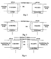
- Fig. 2 illustrates the communications exchanged according to an exemplary embodiment of this invention based on the exemplary C-REVERB1 state discussed above.
- the ATU-C sends information, such as a message or identifier, identifying the MinState value to the ATU-R indicating the minimum length of the state.
- the ATU-C could send information indicating that the MinState value is equal to 1000 DMT symbols for the C-REVERB1 state 250.
- the ATU-R would be required to, for example, wait at least 1000 DMT symbols before the ATU-R transmitter could send R-REVERB2 to the ATU-C. The forwarding of the R-REVERB2 to the ATU-C would thus terminate the C-REVERB 1 state.
- the ATU-R receiver may send the desired length of the state to the ATU-C transmitter and the ATU-C transmitter may terminate the state by, for example, sending a known signal, such as a signal with reverse polarity (inverted) as compared to the signal sent in the state that is being terminated, to the ATU-R receiver.
- a known signal such as a signal with reverse polarity (inverted) as compared to the signal sent in the state that is being terminated
- the ATU-R would send information, such as an identifier or a message, to the ATU-C indicating the minimum length of the state 260, e.g. the MinState value.
- the ATU-R could indicate that the MinState value equals 1000 DMT symbols for C-REVERB1.
- the ATU-C would be required to wait at least 1000 DMT symbols before the ATU-C transmitter could send a known signal, e.g., C-SEGUE1, to the ATU-R, and thus terminate the C-REVERB1 state.
- Fig. 4 illustrates an exemplary embodiment in which both the ATU transmitter and the ATU receiver send the desired length of the states 270 and 280 to each other.
- the larger number of the two MinState values is used to determine the transition out of the current state, and thus there is no need for the signal terminating the state since both transceivers know the state duration.
- the ATU-R would send a message to the ATU-C indicating the minimum length of the state of the receiver (MinState-Rx). For example, the ATU-R could indicate that MinState-Rx would be equal to 2000 DMT symbols for C-REVERB1. Likewise, the ATU-C could send out information, such as a message, to the ATU-R indicating the minimum length of the state of the ATU transmitter (MinState-Tx). For example, the ATU-C could indicate that MinState-Tx is equal to 1000 DMT symbols for C-REVERB 1.
- C-REVERB 1 The duration of C-REVERB 1 would be thus equal to the greater of the MmState-TX and MinState-Rx lengths, In this example, the length of C-REVERB1 would be chosen as the greater of the two since it was specified as being 2000 DMT symbols.
- MinState values for a plurality of states could be stored in memory and upon a determination being made to switch to a next initialization state, the transceivers would have the necessary MinState values to ensure the initialization is correctly completed for the state in question.
- the protocols and methods are used to control the length of the states where the ATU-R is the transmitting transceiver and the ATU-C is the receiving transceiver. Such an example was described above for the control of the length of the R-REVERB3.
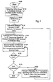
- Fig. 5 illustrates an exemplary embodiment for variable state length initialization according to this invention.
- control begins in step S100 and continues to step S110.
- step S110 a determination is made as to which state(s) require a minimum number of DMT symbols.
- step S120 a first initialization state is selected.
- step S130 assuming the selected state requires a minimum number of DMT symbols, the minimum number of DMT symbols for the selected state is determined.
- Control then continues to step S140.
- step S140 information, such as message, specific signal or identifier, is assembled and forwarded to a second transceiver that specifies the minimum number of DMT symbols for the selected state.
- step S 150 the number of DMT symbols received or transmitted by the second transceiver associated with the selected state is monitored. Then, in step S160, if the number of received or transmitted DMT symbols is equal to or greater than the MinState length, control continues to step S170. Otherwise, control jumps back to step S150.
- step S 170 a determination is made as whether initialization is complete. If initialization is complete, control continues to step S180 where initialization ends and, for example, the transceivers enter steady-state communication. Otherwise, control jumps to step S190 where information, which can, for example, be a predefined signal, is forwarded to the first transceiver specifying the exit of the current initialization state which will allow the entry into another initialization state. Control then continues back to step S130.
- information which can, for example, be a predefined signal
- Fig. 6 outlines a second exemplary embodiment where both of the ATU-C and the ATU-R specify a MinState value for a selected state.
- control begins in step S200 and continues to step S210.
- step S210 a determination is made as to which state(s) require a minimum number of DMT symbols (MinState).
- MinState minimum number of DMT symbols
- step S220 a first initialization state is selected.
- step S230 for each of the ATU-C and ATU-R, the following steps are performed.
- step S240 the minimum number of DMT symbols for the selected state is determined.
- step S250 information, such as a message or identifier, is assembled and forwarded to the other transceiver specifying the minimum number of DMT symbols for the selected state.
- step S260 a comparison is made between the MinState value forwarded by the ATU-R and the MinState value forwarded from the ATU-C and the greater of the two MinState (MaxMinState)values selected. Control then continues to step S270.
- step S270 each of the ATU-C and ATU-R monitor the number of received or transmitted DMT symbols.
- step S280 a determination is made as to whether the MaxMinState value has been met. If the MaxMinState value has been met, control continues to step S290. Otherwise, control jumps back to step S270,
- step S290 a determination is made as to whether initialization is complete, If initialization is complete, control continues to step S300 where the control sequence ends. Otherwise, control jumps back to step S310 where the ATU-C and ATU-R switch to the next initialization state.
- the above-described initialization protocol can be implemented on a telecommunications device, such as a modem, a DSL modem, a ADSL modem, multicarrier transceiver, or the like, or on a separate programmed general purpose computer having a communications device.
- the systems and methods of this invention can also be implemented on special purpose computer, a programmed microprocessor or microcontroller and peripheral integrated circuit elements, an ASIC, or other integrated circuit, a digital signal processor, a hard-wired electronic or logic circuit, such as discrete element circuit, a programmable logic device such as a PLD, PLA, FPGA, PAL, a modem, or the like.
- any device capable of implementing a state machine that is in turn capable of implementing the flow charts illustrated herein can be used to implement the variable state length initialization system according to this invention.
- variable state length initialization system may be implemented partial or fully in hardware using standard logic circuits or VLSI design. Whether software or hardware is used to implement the systems in accordance with this invention is dependent on the speed and/or efficiency requirements of the system, the particular function, and the particular software or hardware systems or microprocessor or microcomputer systems being utilized.
- variable state length initialization systems and methods illustrated herein can be readily implemented in hardware and/or software using any know or later developed systems or structures, devices and/or software by those of ordinary skill in the applicable art from the functional description provided herein and with a general basic knowledge of the computer and telecommunications arts.
- variable state length initialization system can also be implemented by physically incorporating the system and method into a software and/or hardware system, such as the hardware and software systems of a variable state length initialization enabled transceiver.
Applications Claiming Priority (3)
| Application Number | Priority Date | Filing Date | Title |
|---|---|---|---|
| US29669701P | 2001-06-07 | 2001-06-07 | |
| EP05027153A EP1641174B1 (en) | 2001-06-07 | 2002-06-07 | Method and system for variable state length initialization for DSL systems |
| EP02734685A EP1393541B1 (en) | 2001-06-07 | 2002-06-07 | Variable state length initialisation for DSL systems |
Related Parent Applications (3)
| Application Number | Title | Priority Date | Filing Date |
|---|---|---|---|
| EP02734685.7 Division | 2002-06-07 | ||
| EP05027153A Division EP1641174B1 (en) | 2001-06-07 | 2002-06-07 | Method and system for variable state length initialization for DSL systems |
| EP05027153.5 Division | 2005-12-13 |
Publications (3)
| Publication Number | Publication Date |
|---|---|
| EP1912375A2 EP1912375A2 (en) | 2008-04-16 |
| EP1912375A3 EP1912375A3 (en) | 2008-05-21 |
| EP1912375B1 true EP1912375B1 (en) | 2012-06-27 |
Family
ID=23143156
Family Applications (3)
| Application Number | Title | Priority Date | Filing Date |
|---|---|---|---|
| EP08001578A Expired - Lifetime EP1912375B1 (en) | 2001-06-07 | 2002-06-07 | Method and system for variable state length initialization for DSL systems |
| EP05027153A Expired - Lifetime EP1641174B1 (en) | 2001-06-07 | 2002-06-07 | Method and system for variable state length initialization for DSL systems |
| EP02734685A Expired - Lifetime EP1393541B1 (en) | 2001-06-07 | 2002-06-07 | Variable state length initialisation for DSL systems |
Family Applications After (2)
| Application Number | Title | Priority Date | Filing Date |
|---|---|---|---|
| EP05027153A Expired - Lifetime EP1641174B1 (en) | 2001-06-07 | 2002-06-07 | Method and system for variable state length initialization for DSL systems |
| EP02734685A Expired - Lifetime EP1393541B1 (en) | 2001-06-07 | 2002-06-07 | Variable state length initialisation for DSL systems |
Country Status (12)
| Country | Link |
|---|---|
| US (4) | US6647068B2 (ko) |
| EP (3) | EP1912375B1 (ko) |
| JP (3) | JP3970242B2 (ko) |
| KR (5) | KR100956044B1 (ko) |
| AT (2) | ATE385359T1 (ko) |
| AU (3) | AU2002305831B2 (ko) |
| CA (2) | CA2559482C (ko) |
| DE (3) | DE60208022T2 (ko) |
| ES (2) | ES2251594T3 (ko) |
| HK (1) | HK1083960A1 (ko) |
| PT (1) | PT1641174E (ko) |
| WO (1) | WO2002102043A1 (ko) |
Families Citing this family (6)
| Publication number | Priority date | Publication date | Assignee | Title |
|---|---|---|---|---|
| US7033373B2 (en) * | 2000-11-03 | 2006-04-25 | Satiety, Inc. | Method and device for use in minimally invasive placement of space-occupying intragastric devices |
| DE60208022T2 (de) * | 2001-06-07 | 2007-02-15 | Aware, Inc., Bedford | Zustandinitialisierung mit variabler Länge für DSL-Systemen |
| US7418030B2 (en) * | 2004-02-11 | 2008-08-26 | Texas Instruments Incorporated | Flexible initialization method for DSL communication systems |
| ES2389910T3 (es) * | 2004-10-15 | 2012-11-02 | Aware, Inc. | Repetición de símbolos DMT en presencia de ruido impulsivo |
| US8363613B2 (en) | 2010-05-13 | 2013-01-29 | Juniper Networks, Inc. | Increasing throughput by adaptively changing PDU size in wireless networks under low SNR conditions |
| EP3195667A4 (en) * | 2014-09-18 | 2018-04-04 | Intel IP Corporation | Scheme of finite power transmission statuses for low cost wireless broadband communication system |
Family Cites Families (41)
| Publication number | Priority date | Publication date | Assignee | Title |
|---|---|---|---|---|
| US4679227A (en) * | 1985-05-20 | 1987-07-07 | Telebit Corporation | Ensemble modem structure for imperfect transmission media |
| JPH02268334A (ja) * | 1989-04-11 | 1990-11-02 | Fuji Xerox Co Ltd | ステート制御方式 |
| US5285474A (en) | 1992-06-12 | 1994-02-08 | The Board Of Trustees Of The Leland Stanford, Junior University | Method for equalizing a multicarrier signal in a multicarrier communication system |
| US5479447A (en) | 1993-05-03 | 1995-12-26 | The Board Of Trustees Of The Leland Stanford, Junior University | Method and apparatus for adaptive, variable bandwidth, high-speed data transmission of a multicarrier signal over digital subscriber lines |
| US5400322A (en) | 1993-08-20 | 1995-03-21 | Amati Communications Corp. | Updating of bit allocations in a multicarrier modulation transmission system |
| US5708659A (en) | 1993-10-20 | 1998-01-13 | Lsi Logic Corporation | Method for hashing in a packet network switching system |
| US5539777A (en) | 1995-01-26 | 1996-07-23 | Motorola, Inc. | Method and apparatus for a DMT receiver having a data de-formatter coupled directly to a constellation decoder |
| US5606577A (en) | 1995-01-26 | 1997-02-25 | Motorola Inc. | Method and apparatus for a DMT transmitter having a data for matter coupled directly to a constellation encoder |
| US5680394A (en) | 1995-07-11 | 1997-10-21 | Amati Communications Corporation | Time division duplexed high speed data transmission system and method |
| US5825474A (en) * | 1995-10-27 | 1998-10-20 | Identix Corporation | Heated optical platen cover for a fingerprint imaging system |
| US6137839A (en) * | 1996-05-09 | 2000-10-24 | Texas Instruments Incorporated | Variable scaling of 16-bit fixed point fast fourier forward and inverse transforms to improve precision for implementation of discrete multitone for asymmetric digital subscriber loops |
| US6021167A (en) * | 1996-05-09 | 2000-02-01 | Texas Instruments Incorporated | Fast equalizer training and frame synchronization algorithms for discrete multi-tone (DMT) system |
| US5999563A (en) | 1996-05-09 | 1999-12-07 | Texas Instruments Incorporated | Rate negotiation for variable-rate digital subscriber line signaling |
| US5751701A (en) * | 1996-07-19 | 1998-05-12 | Globespan Technologies, Inc. | Rate adaptive digital subscriber line ("RADSL") modem |
| US6285654B1 (en) | 1996-08-22 | 2001-09-04 | Tellabs Operations, Inc. | Apparatus and method for symbol alignment in a multi-point OFDM or DMT digital communications system |
| US5987069A (en) * | 1996-12-24 | 1999-11-16 | Gte Government Systems Corporation | Method and apparatus for variably allocating upstream and downstream communication spectra |
| KR100421212B1 (ko) | 1997-05-10 | 2004-05-22 | 삼성전자주식회사 | 디지탈가입자선에서고속다수반송파데이터신호의연속전송을위한다수반송파시스템의다점전송방법 |
| US6064692A (en) | 1997-06-20 | 2000-05-16 | Amati Communications Corporation | Protocol for transceiver initialization |
| US6314102B1 (en) | 1997-07-10 | 2001-11-06 | Alcatel | Telecommunications system for providing both narrowband and broadband services to subscribers |
| US6219378B1 (en) | 1997-09-17 | 2001-04-17 | Texas Instruments Incorporated | Digital subscriber line modem initialization |
| GB2329796A (en) * | 1997-09-29 | 1999-03-31 | Motorola Ltd | Increased data rate by reduction of training data |
| US6134283A (en) | 1997-11-18 | 2000-10-17 | Amati Communications Corporation | Method and system for synchronizing time-division-duplexed transceivers |
| US6084906A (en) | 1997-12-17 | 2000-07-04 | Integrated Telecom Express | ADSL transceiver implemented with associated bit and energy loading integrated circuit |
| US6278728B1 (en) | 1998-03-18 | 2001-08-21 | Cisco Technology, Inc. | Remote XDSL transceiver unit and method of operation |
| CA2445334C (en) * | 1998-04-01 | 2008-08-05 | Matsushita Graphic Communication Systems, Inc. | Activation of multiple xdsl modems with implicit channel probe |
| US6526105B1 (en) * | 1998-05-29 | 2003-02-25 | Tellabs, Operations, Inc. | Time domain equalization for discrete multi-tone systems |
| EP1090490B1 (en) * | 1998-06-26 | 2004-09-15 | Aware, Inc. | Multicarrier communication with variable overhead rate |
| KR100281409B1 (ko) * | 1998-11-05 | 2001-02-01 | 정선종 | 범용 디에스엘 모뎀 |
| US6279022B1 (en) | 1998-11-13 | 2001-08-21 | Integrated Telecom Express, Inc. | System and method for detecting symbol boundary in multi-carrier transmission systems |
| US5999540A (en) | 1998-12-22 | 1999-12-07 | Cisco Technology, Inc. | Rate adaptive XDSL communication system and method |
| KR20000056041A (ko) * | 1999-02-12 | 2000-09-15 | 김영환 | 에이디에스엘 모뎀의 고정 레이트 제어장치 |
| US6324212B1 (en) | 1999-02-12 | 2001-11-27 | Siemens Information And Communication Networks, Inc. | Apparatus using low spectrum selectively for providing both ADSL and POTS service |
| DE69937401T2 (de) * | 1999-05-21 | 2008-07-24 | Fujitsu Ltd., Kawasaki | Verfahren und vorrichtung zur nachrichtenübertragung über eine digitale teilnehmeranschlussleitung |
| AU2108301A (en) * | 1999-12-16 | 2001-06-25 | Aware, Inc. | Bit allocation method in a multicarrier system |
| WO2001082543A2 (en) * | 2000-04-22 | 2001-11-01 | Atheros Communications, Inc. | Multi-carrier communication systems employing variable ofdm-symbol rates and number of carriers |
| US7418043B2 (en) * | 2000-07-19 | 2008-08-26 | Lot 41 Acquisition Foundation, Llc | Software adaptable high performance multicarrier transmission protocol |
| US7103096B2 (en) * | 2000-10-12 | 2006-09-05 | 3Com Corporation | Performance evaluation of multicarrier channels with forward error correction and automatic retransmission request |
| US20020108011A1 (en) * | 2000-12-11 | 2002-08-08 | Reza Tanha | Dual interface serial bus |
| US7068707B2 (en) * | 2001-03-08 | 2006-06-27 | Qualcomm, Inc. | Method and apparatus for tracking signals in a wireless communication system |
| DE60208022T2 (de) * | 2001-06-07 | 2007-02-15 | Aware, Inc., Bedford | Zustandinitialisierung mit variabler Länge für DSL-Systemen |
| US6952430B2 (en) * | 2001-12-31 | 2005-10-04 | Globespanvirata Incorporated | System and method for interfacing a data link protocol engine and a physical layer |
-
2002
- 2002-06-07 DE DE60208022T patent/DE60208022T2/de not_active Expired - Lifetime
- 2002-06-07 AT AT05027153T patent/ATE385359T1/de active
- 2002-06-07 ES ES02734685T patent/ES2251594T3/es not_active Expired - Lifetime
- 2002-06-07 DE DE60224892.2A patent/DE60224892C5/de not_active Expired - Lifetime
- 2002-06-07 KR KR1020077012713A patent/KR100956044B1/ko active IP Right Grant
- 2002-06-07 EP EP08001578A patent/EP1912375B1/en not_active Expired - Lifetime
- 2002-06-07 EP EP05027153A patent/EP1641174B1/en not_active Expired - Lifetime
- 2002-06-07 WO PCT/US2002/017752 patent/WO2002102043A1/en active IP Right Grant
- 2002-06-07 KR KR1020107005346A patent/KR101002241B1/ko active IP Right Grant
- 2002-06-07 KR KR1020037001774A patent/KR100921587B1/ko active IP Right Grant
- 2002-06-07 DE DE60224892T patent/DE60224892T2/de not_active Expired - Lifetime
- 2002-06-07 CA CA2559482A patent/CA2559482C/en not_active Expired - Lifetime
- 2002-06-07 EP EP02734685A patent/EP1393541B1/en not_active Expired - Lifetime
- 2002-06-07 US US10/163,692 patent/US6647068B2/en not_active Expired - Lifetime
- 2002-06-07 KR KR1020107016788A patent/KR101059713B1/ko active IP Right Grant
- 2002-06-07 ES ES05027153T patent/ES2298920T3/es not_active Expired - Lifetime
- 2002-06-07 JP JP2003504650A patent/JP3970242B2/ja not_active Expired - Lifetime
- 2002-06-07 PT PT05027153T patent/PT1641174E/pt unknown
- 2002-06-07 AU AU2002305831A patent/AU2002305831B2/en not_active Ceased
- 2002-06-07 AT AT02734685T patent/ATE313213T1/de active
- 2002-06-07 CA CA002416302A patent/CA2416302C/en not_active Expired - Lifetime
- 2002-06-07 KR KR1020097021513A patent/KR100986951B1/ko active IP Right Grant
-
2003
- 2003-07-31 US US10/630,673 patent/US7272171B2/en active Active
-
2006
- 2006-05-29 HK HK06106207A patent/HK1083960A1/xx not_active IP Right Cessation
- 2006-07-27 AU AU2006203214A patent/AU2006203214B2/en not_active Ceased
- 2006-12-19 JP JP2006341439A patent/JP4415004B2/ja not_active Expired - Fee Related
- 2006-12-19 JP JP2006341447A patent/JP4542087B2/ja not_active Expired - Fee Related
-
2007
- 2007-07-25 US US11/828,134 patent/US7826545B2/en not_active Expired - Lifetime
-
2008
- 2008-10-15 AU AU2008229943A patent/AU2008229943A1/en not_active Abandoned
-
2010
- 2010-10-20 US US12/908,321 patent/US8208520B2/en not_active Expired - Lifetime
Also Published As
Similar Documents
| Publication | Publication Date | Title |
|---|---|---|
| CN102075286B (zh) | 用于高速率正交频分复用通信的系统和方法 | |
| EP1755253B1 (en) | Diagnostic method and transceiver for multicarrier modems | |
| US8208520B2 (en) | Variable state length initialization | |
| AU2002305831A1 (en) | Variable state length initialization | |
| CA2726826C (en) | Diagnostic methods and systems for multicarrier modems |
Legal Events
| Date | Code | Title | Description |
|---|---|---|---|
| PUAI | Public reference made under article 153(3) epc to a published international application that has entered the european phase |
Free format text: ORIGINAL CODE: 0009012 |
|
| AC | Divisional application: reference to earlier application |
Ref document number: 1641174 Country of ref document: EP Kind code of ref document: P Ref document number: 1393541 Country of ref document: EP Kind code of ref document: P |
|
| AK | Designated contracting states |
Kind code of ref document: A2 Designated state(s): AT BE CH CY DE DK ES FI FR GB GR IE IT LI LU MC NL PT SE TR |
|
| PUAL | Search report despatched |
Free format text: ORIGINAL CODE: 0009013 |
|
| AK | Designated contracting states |
Kind code of ref document: A3 Designated state(s): AT BE CH CY DE DK ES FI FR GB GR IE IT LI LU MC NL PT SE TR |
|
| REG | Reference to a national code |
Ref country code: HK Ref legal event code: DE Ref document number: 1110458 Country of ref document: HK |
|
| 17P | Request for examination filed |
Effective date: 20081120 |
|
| AKX | Designation fees paid |
Designated state(s): AT BE CH CY DE DK ES FI FR GB GR IE IT LI LU MC NL PT SE TR |
|
| 17Q | First examination report despatched |
Effective date: 20090113 |
|
| RAP1 | Party data changed (applicant data changed or rights of an application transferred) |
Owner name: DAPHIMO CO. B.V., LLC |
|
| RAP1 | Party data changed (applicant data changed or rights of an application transferred) |
Owner name: DAPHIMO CO. B.V., LLC |
|
| GRAP | Despatch of communication of intention to grant a patent |
Free format text: ORIGINAL CODE: EPIDOSNIGR1 |
|
| GRAJ | Information related to disapproval of communication of intention to grant by the applicant or resumption of examination proceedings by the epo deleted |
Free format text: ORIGINAL CODE: EPIDOSDIGR1 |
|
| GRAP | Despatch of communication of intention to grant a patent |
Free format text: ORIGINAL CODE: EPIDOSNIGR1 |
|
| GRAS | Grant fee paid |
Free format text: ORIGINAL CODE: EPIDOSNIGR3 |
|
| GRAA | (expected) grant |
Free format text: ORIGINAL CODE: 0009210 |
|
| AC | Divisional application: reference to earlier application |
Ref document number: 1641174 Country of ref document: EP Kind code of ref document: P Ref document number: 1393541 Country of ref document: EP Kind code of ref document: P |
|
| AK | Designated contracting states |
Kind code of ref document: B1 Designated state(s): AT BE CH CY DE DK ES FI FR GB GR IE IT LI LU MC NL PT SE TR |
|
| REG | Reference to a national code |
Ref country code: GB Ref legal event code: FG4D |
|
| REG | Reference to a national code |
Ref country code: CH Ref legal event code: EP |
|
| REG | Reference to a national code |
Ref country code: AT Ref legal event code: REF Ref document number: 564670 Country of ref document: AT Kind code of ref document: T Effective date: 20120715 |
|
| REG | Reference to a national code |
Ref country code: IE Ref legal event code: FG4D |
|
| REG | Reference to a national code |
Ref country code: DE Ref legal event code: R096 Ref document number: 60243240 Country of ref document: DE Effective date: 20120823 |
|
| PG25 | Lapsed in a contracting state [announced via postgrant information from national office to epo] |
Ref country code: FI Free format text: LAPSE BECAUSE OF FAILURE TO SUBMIT A TRANSLATION OF THE DESCRIPTION OR TO PAY THE FEE WITHIN THE PRESCRIBED TIME-LIMIT Effective date: 20120627 Ref country code: SE Free format text: LAPSE BECAUSE OF FAILURE TO SUBMIT A TRANSLATION OF THE DESCRIPTION OR TO PAY THE FEE WITHIN THE PRESCRIBED TIME-LIMIT Effective date: 20120627 |
|
| REG | Reference to a national code |
Ref country code: NL Ref legal event code: VDEP Effective date: 20120627 |
|
| REG | Reference to a national code |
Ref country code: AT Ref legal event code: MK05 Ref document number: 564670 Country of ref document: AT Kind code of ref document: T Effective date: 20120627 |
|
| PG25 | Lapsed in a contracting state [announced via postgrant information from national office to epo] |
Ref country code: GR Free format text: LAPSE BECAUSE OF FAILURE TO SUBMIT A TRANSLATION OF THE DESCRIPTION OR TO PAY THE FEE WITHIN THE PRESCRIBED TIME-LIMIT Effective date: 20120928 |
|
| PG25 | Lapsed in a contracting state [announced via postgrant information from national office to epo] |
Ref country code: AT Free format text: LAPSE BECAUSE OF FAILURE TO SUBMIT A TRANSLATION OF THE DESCRIPTION OR TO PAY THE FEE WITHIN THE PRESCRIBED TIME-LIMIT Effective date: 20120627 Ref country code: CY Free format text: LAPSE BECAUSE OF FAILURE TO SUBMIT A TRANSLATION OF THE DESCRIPTION OR TO PAY THE FEE WITHIN THE PRESCRIBED TIME-LIMIT Effective date: 20120627 Ref country code: BE Free format text: LAPSE BECAUSE OF NON-PAYMENT OF DUE FEES Effective date: 20120627 |
|
| PG25 | Lapsed in a contracting state [announced via postgrant information from national office to epo] |
Ref country code: PT Free format text: LAPSE BECAUSE OF FAILURE TO SUBMIT A TRANSLATION OF THE DESCRIPTION OR TO PAY THE FEE WITHIN THE PRESCRIBED TIME-LIMIT Effective date: 20121029 Ref country code: IT Free format text: LAPSE BECAUSE OF FAILURE TO SUBMIT A TRANSLATION OF THE DESCRIPTION OR TO PAY THE FEE WITHIN THE PRESCRIBED TIME-LIMIT Effective date: 20120627 |
|
| PG25 | Lapsed in a contracting state [announced via postgrant information from national office to epo] |
Ref country code: NL Free format text: LAPSE BECAUSE OF FAILURE TO SUBMIT A TRANSLATION OF THE DESCRIPTION OR TO PAY THE FEE WITHIN THE PRESCRIBED TIME-LIMIT Effective date: 20120627 |
|
| PG25 | Lapsed in a contracting state [announced via postgrant information from national office to epo] |
Ref country code: ES Free format text: LAPSE BECAUSE OF FAILURE TO SUBMIT A TRANSLATION OF THE DESCRIPTION OR TO PAY THE FEE WITHIN THE PRESCRIBED TIME-LIMIT Effective date: 20121008 Ref country code: DK Free format text: LAPSE BECAUSE OF FAILURE TO SUBMIT A TRANSLATION OF THE DESCRIPTION OR TO PAY THE FEE WITHIN THE PRESCRIBED TIME-LIMIT Effective date: 20120627 |
|
| PLBE | No opposition filed within time limit |
Free format text: ORIGINAL CODE: 0009261 |
|
| STAA | Information on the status of an ep patent application or granted ep patent |
Free format text: STATUS: NO OPPOSITION FILED WITHIN TIME LIMIT |
|
| 26N | No opposition filed |
Effective date: 20130328 |
|
| REG | Reference to a national code |
Ref country code: DE Ref legal event code: R097 Ref document number: 60243240 Country of ref document: DE Effective date: 20130328 |
|
| PG25 | Lapsed in a contracting state [announced via postgrant information from national office to epo] |
Ref country code: MC Free format text: LAPSE BECAUSE OF FAILURE TO SUBMIT A TRANSLATION OF THE DESCRIPTION OR TO PAY THE FEE WITHIN THE PRESCRIBED TIME-LIMIT Effective date: 20120627 |
|
| REG | Reference to a national code |
Ref country code: CH Ref legal event code: PL |
|
| REG | Reference to a national code |
Ref country code: IE Ref legal event code: MM4A |
|
| PG25 | Lapsed in a contracting state [announced via postgrant information from national office to epo] |
Ref country code: IE Free format text: LAPSE BECAUSE OF NON-PAYMENT OF DUE FEES Effective date: 20130607 Ref country code: LI Free format text: LAPSE BECAUSE OF NON-PAYMENT OF DUE FEES Effective date: 20130630 Ref country code: CH Free format text: LAPSE BECAUSE OF NON-PAYMENT OF DUE FEES Effective date: 20130630 |
|
| REG | Reference to a national code |
Ref country code: HK Ref legal event code: WD Ref document number: 1110458 Country of ref document: HK |
|
| PG25 | Lapsed in a contracting state [announced via postgrant information from national office to epo] |
Ref country code: TR Free format text: LAPSE BECAUSE OF FAILURE TO SUBMIT A TRANSLATION OF THE DESCRIPTION OR TO PAY THE FEE WITHIN THE PRESCRIBED TIME-LIMIT Effective date: 20120627 |
|
| PG25 | Lapsed in a contracting state [announced via postgrant information from national office to epo] |
Ref country code: LU Free format text: LAPSE BECAUSE OF NON-PAYMENT OF DUE FEES Effective date: 20130607 |
|
| REG | Reference to a national code |
Ref country code: DE Ref legal event code: R082 Ref document number: 60243240 Country of ref document: DE Representative=s name: MUELLER-BORE & PARTNER PATENTANWAELTE PARTG MB, DE Ref country code: DE Ref legal event code: R081 Ref document number: 60243240 Country of ref document: DE Owner name: INTELLECTUAL VENTURES LL LLC, WILMINGTON, US Free format text: FORMER OWNER: DAPHIMO CO. B.V. LLC., WILMINGTON, DEL., US Ref country code: DE Ref legal event code: R082 Ref document number: 60243240 Country of ref document: DE Representative=s name: BARDEHLE PAGENBERG PARTNERSCHAFT MBB PATENTANW, DE |
|
| REG | Reference to a national code |
Ref country code: FR Ref legal event code: PLFP Year of fee payment: 15 |
|
| REG | Reference to a national code |
Ref country code: FR Ref legal event code: TP Owner name: INTELLECTUAL VENTURES II LLC, US Effective date: 20160308 |
|
| REG | Reference to a national code |
Ref country code: DE Ref legal event code: R082 Ref document number: 60243240 Country of ref document: DE Representative=s name: BARDEHLE PAGENBERG PARTNERSCHAFT MBB PATENTANW, DE |
|
| REG | Reference to a national code |
Ref country code: FR Ref legal event code: PLFP Year of fee payment: 16 |
|
| REG | Reference to a national code |
Ref country code: FR Ref legal event code: PLFP Year of fee payment: 17 |
|
| PGFP | Annual fee paid to national office [announced via postgrant information from national office to epo] |
Ref country code: DE Payment date: 20210512 Year of fee payment: 20 Ref country code: FR Payment date: 20210520 Year of fee payment: 20 |
|
| PGFP | Annual fee paid to national office [announced via postgrant information from national office to epo] |
Ref country code: GB Payment date: 20210528 Year of fee payment: 20 |
|
| REG | Reference to a national code |
Ref country code: DE Ref legal event code: R071 Ref document number: 60243240 Country of ref document: DE |
|
| REG | Reference to a national code |
Ref country code: GB Ref legal event code: PE20 Expiry date: 20220606 |
|
| PG25 | Lapsed in a contracting state [announced via postgrant information from national office to epo] |
Ref country code: GB Free format text: LAPSE BECAUSE OF EXPIRATION OF PROTECTION Effective date: 20220606 |