EP1912104A2 - Obstruction-determining apparatus for preventing mobile robot from becoming obstructed and boundary-estimation method and medium using the obstruction-determining apparatus - Google Patents
Obstruction-determining apparatus for preventing mobile robot from becoming obstructed and boundary-estimation method and medium using the obstruction-determining apparatus Download PDFInfo
- Publication number
- EP1912104A2 EP1912104A2 EP07116921A EP07116921A EP1912104A2 EP 1912104 A2 EP1912104 A2 EP 1912104A2 EP 07116921 A EP07116921 A EP 07116921A EP 07116921 A EP07116921 A EP 07116921A EP 1912104 A2 EP1912104 A2 EP 1912104A2
- Authority
- EP
- European Patent Office
- Prior art keywords
- mobile robot
- obstruction
- module
- contact
- niche
- Prior art date
- Legal status (The legal status is an assumption and is not a legal conclusion. Google has not performed a legal analysis and makes no representation as to the accuracy of the status listed.)
- Withdrawn
Links
Images


Classifications
-
- G—PHYSICS
- G05—CONTROLLING; REGULATING
- G05D—SYSTEMS FOR CONTROLLING OR REGULATING NON-ELECTRIC VARIABLES
- G05D1/00—Control of position, course or altitude of land, water, air, or space vehicles, e.g. automatic pilot
- G05D1/02—Control of position or course in two dimensions
- G05D1/021—Control of position or course in two dimensions specially adapted to land vehicles
- G05D1/0227—Control of position or course in two dimensions specially adapted to land vehicles using mechanical sensing means, e.g. for sensing treated area
-
- A—HUMAN NECESSITIES
- A47—FURNITURE; DOMESTIC ARTICLES OR APPLIANCES; COFFEE MILLS; SPICE MILLS; SUCTION CLEANERS IN GENERAL
- A47L—DOMESTIC WASHING OR CLEANING; SUCTION CLEANERS IN GENERAL
- A47L11/00—Machines for cleaning floors, carpets, furniture, walls, or wall coverings
- A47L11/40—Parts or details of machines not provided for in groups A47L11/02 - A47L11/38, or not restricted to one of these groups, e.g. handles, arrangements of switches, skirts, buffers, levers
- A47L11/4061—Steering means; Means for avoiding obstacles; Details related to the place where the driver is accommodated
-
- A—HUMAN NECESSITIES
- A47—FURNITURE; DOMESTIC ARTICLES OR APPLIANCES; COFFEE MILLS; SPICE MILLS; SUCTION CLEANERS IN GENERAL
- A47L—DOMESTIC WASHING OR CLEANING; SUCTION CLEANERS IN GENERAL
- A47L11/00—Machines for cleaning floors, carpets, furniture, walls, or wall coverings
- A47L11/40—Parts or details of machines not provided for in groups A47L11/02 - A47L11/38, or not restricted to one of these groups, e.g. handles, arrangements of switches, skirts, buffers, levers
- A47L11/4072—Arrangement of castors or wheels
-
- B—PERFORMING OPERATIONS; TRANSPORTING
- B25—HAND TOOLS; PORTABLE POWER-DRIVEN TOOLS; MANIPULATORS
- B25J—MANIPULATORS; CHAMBERS PROVIDED WITH MANIPULATION DEVICES
- B25J13/00—Controls for manipulators
- B25J13/08—Controls for manipulators by means of sensing devices, e.g. viewing or touching devices
-
- B—PERFORMING OPERATIONS; TRANSPORTING
- B25—HAND TOOLS; PORTABLE POWER-DRIVEN TOOLS; MANIPULATORS
- B25J—MANIPULATORS; CHAMBERS PROVIDED WITH MANIPULATION DEVICES
- B25J19/00—Accessories fitted to manipulators, e.g. for monitoring, for viewing; Safety devices combined with or specially adapted for use in connection with manipulators
- B25J19/02—Sensing devices
-
- B—PERFORMING OPERATIONS; TRANSPORTING
- B25—HAND TOOLS; PORTABLE POWER-DRIVEN TOOLS; MANIPULATORS
- B25J—MANIPULATORS; CHAMBERS PROVIDED WITH MANIPULATION DEVICES
- B25J9/00—Programme-controlled manipulators
- B25J9/10—Programme-controlled manipulators characterised by positioning means for manipulator elements
- B25J9/1005—Programme-controlled manipulators characterised by positioning means for manipulator elements comprising adjusting means
- B25J9/101—Programme-controlled manipulators characterised by positioning means for manipulator elements comprising adjusting means using limit-switches, -stops
-
- B—PERFORMING OPERATIONS; TRANSPORTING
- B25—HAND TOOLS; PORTABLE POWER-DRIVEN TOOLS; MANIPULATORS
- B25J—MANIPULATORS; CHAMBERS PROVIDED WITH MANIPULATION DEVICES
- B25J9/00—Programme-controlled manipulators
- B25J9/16—Programme controls
- B25J9/1656—Programme controls characterised by programming, planning systems for manipulators
- B25J9/1664—Programme controls characterised by programming, planning systems for manipulators characterised by motion, path, trajectory planning
-
- A—HUMAN NECESSITIES
- A47—FURNITURE; DOMESTIC ARTICLES OR APPLIANCES; COFFEE MILLS; SPICE MILLS; SUCTION CLEANERS IN GENERAL
- A47L—DOMESTIC WASHING OR CLEANING; SUCTION CLEANERS IN GENERAL
- A47L2201/00—Robotic cleaning machines, i.e. with automatic control of the travelling movement or the cleaning operation
- A47L2201/04—Automatic control of the travelling movement; Automatic obstacle detection
-
- Y—GENERAL TAGGING OF NEW TECHNOLOGICAL DEVELOPMENTS; GENERAL TAGGING OF CROSS-SECTIONAL TECHNOLOGIES SPANNING OVER SEVERAL SECTIONS OF THE IPC; TECHNICAL SUBJECTS COVERED BY FORMER USPC CROSS-REFERENCE ART COLLECTIONS [XRACs] AND DIGESTS
- Y10—TECHNICAL SUBJECTS COVERED BY FORMER USPC
- Y10S—TECHNICAL SUBJECTS COVERED BY FORMER USPC CROSS-REFERENCE ART COLLECTIONS [XRACs] AND DIGESTS
- Y10S901/00—Robots
- Y10S901/01—Mobile robot
Landscapes
- Engineering & Computer Science (AREA)
- Mechanical Engineering (AREA)
- Robotics (AREA)
- Remote Sensing (AREA)
- Aviation & Aerospace Engineering (AREA)
- Radar, Positioning & Navigation (AREA)
- Physics & Mathematics (AREA)
- General Physics & Mathematics (AREA)
- Automation & Control Theory (AREA)
- Human Computer Interaction (AREA)
- Manipulator (AREA)
- Control Of Position, Course, Altitude, Or Attitude Of Moving Bodies (AREA)
- Electric Vacuum Cleaner (AREA)
- Mechanisms For Operating Contacts (AREA)
Abstract
Description
- This application claims priority benefit from
Korean Patent Application No. 10-2006-0098162 filed on October 9, 2006 - Embodiments relate to an obstruction-determining apparatus for preventing a mobile robot from becoming obstructed and a boundary-estimation method and medium using the obstruction-determining apparatus, and more particularly to a obstruction-determining apparatus which can determine whether a mobile robot is obstructed in a niche and enable a mobile robot to easily escape from an obstacle if it is determined that the mobile robot is obstructed in the niche, and a boundary-estimation method and medium for estimating the boundaries of an obstacle with a niche using the obstruction-determining apparatus.
- In recent years, mobile robots have been widely commercialized not only for industrial purposes but also for domestic and business purposes. As a result, a variety of types of mobile robots such as cleaning robots, guide robots, and security robots have been developed.
- Mobile robots perform their functions while autonomously navigating in an indoor environment. Mobile robots can recognize walls or obstacles with the aid of a sensor or with reference to a map input thereto in advance, and can thus effectively travel from place to place while avoiding such obstacles.
- Conventionally, a plurality of sensors have been used to detect an obstacle or a step difference, and thus to prevent a mobile robot from colliding with the obstacle or falling over. In this case, however, a mobile robot may not be able to recognize an empty space or a niche under the furniture as an obstacle, which is a problem. The term "niche", as used herein, denotes an empty space between the floor and an object that is placed above the floor.
- A mobile robot may be obstructed in a niche when an upper portion of the mobile robot cannot pass through the niche, even if a lower portion of the mobile robot can pass through the niche. In this case, a sensor of the mobile robot does not recognize the niche as an obstacle, and, thus, the mobile robot attempts to keep traveling toward the niche, thereby becoming obstructed in the niche and applying an excessive load to a driving module of the mobile robot. As a result, the driving module of the mobile robot may be severely damaged.
- For example, a cleaning robot is likely to be stuck in a niche under furniture near the wall while performing a wall-following function.
- Once a mobile robot is stuck in a niche, a user must pull the mobile robot out from the niche or drive the mobile robot to escape from the niche through manual manipulation.
- In an aspect of embodiments, there is provided an obstruction-determining apparatus which can determine whether a mobile robot is obstructed in a niche and which can enable a mobile robot to easily escape from an obstacle if the mobile robot is determined to be obstructed in the niche.
- In an aspect of embodiments, there is provided a boundary-estimation method which can enable a mobile robot to avoid an obstacle with a niche by estimating the boundaries of the obstacle.
- According to an aspect of embodiments, there is provided an obstruction-determining apparatus which is mounted on a mobile robot and determines whether the mobile robot is obstructed. The obstruction-determining apparatus includes a contact module which collides with an obstacle above the mobile robot; a contact-operating module which rotates or moves linearly as a result of the collision between the contact module and the obstacle; and a sensing module which detects the rotation or the linear movement of the contact-operating module and determines whether the mobile robot is obstructed in a niche.
- According to another aspect of embodiments, there is provided a mobile robot. The mobile robot includes a main body, a obstruction-determining module which determines whether the main body is obstructed in a niche, and a driving control module which controls movement of the main body if the main body is determined to be obstructed in a niche, wherein the obstruction-determining module collides with an obstacle above the mobile robot, rotates or moves linearly as a result of the collision between the obstruction-determining module and the obstacle, and determines whether the mobile robot is obstructed in a niche by detecting the rotation or the linear movement.
- According to another aspect of embodiments, there is provided a boundary-estimation method using an obstruction-determining apparatus. The boundary-estimation method includes allowing a first obstruction-determining module of a plurality of obstruction-determining modules to determine that a mobile robot is obstructed in a niche, the obstruction-determining modules being mounted on the mobile robot, rotating the mobile robot until a second obstruction-determining module of the obstruction-determining modules also determines that the mobile robot is obstructed in the niche, and estimating a boundary of the obstacle based on a plurality of obstructed positions of the mobile robot respectively detected by the obstruction-determining modules.
- According to another aspect of embodiments, there is provided an obstruction-determining apparatus which is mounted on a mobile robot and determines whether the mobile robot is obstructed, the obstruction-determining apparatus including a contact-operating module to rotate or to move linearly as a result of a collision above the mobile robot between the obstruction-determining apparatus and the obstacle; and a sensing module to detect the rotation or the linear movement of the obstruction-determining apparatus and to determine whether the mobile robot is obstructed in a niche.
- According to another aspect of embodiments, there is provided at least one computer readable medium storing computer readable instructions to implement methods of embodiments.
- These and/or other aspects, features, and advantages will become apparent and more readily appreciated from the following description of exemplary embodiments, taken in conjunction with the accompanying drawings of which:
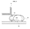
- FIG. 1 is a diagram illustrating a mobile robot equipped with an obstruction-determining apparatus according to an exemplary embodiment;
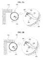
- FIGS. 2A and 2B are diagrams illustrating an obstruction-determining apparatus according to another exemplary embodiment;
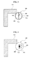
- FIG. 3 is a diagram illustrating an obstruction-determining apparatus according to a further exemplary embodiment;
- FIG. 4 is a diagram illustrating an obstruction-determining apparatus according to another exemplary embodiment;
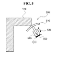
- FIG. 5 is a diagram illustrating an obstruction-determining apparatus according to a further exemplary embodiment;
- FIG. 6 is a block diagram of a mobile robot equipped with an obstruction-determining apparatus according to an exemplary embodiment;
- FIG. 7 is a flowchart illustrating a boundary-estimation method using obstruction determination according to an exemplary embodiment; and
- FIGS. 8A and 8B are diagrams for explaining the movement of a mobile robot using the boundary-estimation method illustrated in FIG. 7.
- Reference will now be made in detail to exemplary embodiments, examples of which are illustrated in the accompanying drawings, wherein like reference numerals refer to the like elements throughout. Exemplary embodiments are described below by referring to the figures.
- FIG. 1 is a diagram illustrating a mobile robot equipped with an obstruction-determining
apparatus 100 according to an exemplary embodiment. Referring to FIG. 1, the obstruction-determiningapparatus 100 may be mounted on top of amobile robot 150. Themobile robot 150 may properly detect and avoid anobstacle 110 if theobstacle 110 does not have any niche like a wall. However, theobstacle 110 has a niche at the bottom. Thus, themobile robot 150 may mistakenly determine that no obstacle exists in its heading, and then keep moving in its heading. Then, an upper portion of themobile robot 150 may collide with a corner of theobstacle 110 and get stuck in the niche. - The obstruction-determining
apparatus 100 prevents themobile robot 150 from becoming obstructed in theniche 110, and determines whether themobile robot 150 is stuck in theniche 110. The obstruction-determiningapparatus 100 may be mounted on top of themobile robot 150, as illustrated in FIG. 1. In this case, the obstruction-determiningapparatus 100 can prevent themobile robot 150 from being completely stuck in theniche 110 even if themobile robot 150 collides with theobstacle 110. - FIGS. 2A and 2B are diagrams illustrating an obstruction-determining
apparatus 200 according to an exemplary embodiment. Referring to FIGS. 2A and 2B, the obstruction-determiningapparatus 200 includes acontact module 210, a contact-operating module 230, and asensing module 250. - The
contact module 210 may contact anobstacle 110 which is located above a niche. If a mobile robot is equipped with no such contact module, an upper portion of the mobile robot may directly collide with theobstacle 110. According to an exemplary embodiment, the obstruction-determiningapparatus 200 is mounted on a mobile robot. Then, thecontact module 210, instead of an upper portion of the mobile robot, collides with theobstacle 110, thereby preventing the mobile robot from crashing into theobstacle 110. Referring to FIGS. 2A and 2B, thecontact module 210 may be formed as a ring or a circular plate. Thecontact module 210 may comprise a center portion and a plurality ofsawtooth indentations 220 which are formed along the inner circumference of thecontact module 210. When thecontact module 210 collides with theobstacle 110, thecontact module 210 rotates about a rotationaxial member 260. - When the
contact module 210 contacts theobstacle 110, the contact-operatingmodule 230 moves linearly or rotates according to the movement of thecontact module 210. The contact-operatingmodule 230 comprises a detent which is attached to the rotationaxial member 260, and engages thesawtooth indentations 220. The detent may be formed as a bar with an end tip that engages thesawtooth indentations 220. When thecontact module 210 rotates clockwise upon contact with theobstacle 110, the detent may rotate along with thecontact module 210 by engaging thesawtooth indentations 220 of thecontact module 210. However, when thecontact module 210 rotates counterclockwise, the detent does not engage thesawtooth indentations 220 of thecontact module 210. Thus, the detent does not rotate along with thecontact module 210. - The contact-operating
module 230 may comprise aspring 240 which maintains the detent within a predetermined angle range. In detail, thespring 240 maintains the detent within a predetermined angle range. In addition, when thecontact module 210 rotates clockwise, thespring 240 applies a reaction force to the detent, thus preventing the detent from rotating along with thecontact module 210 and interfering with a forward movement of a mobile robot equipped with the obstruction-determiningapparatus 200. Due to the detent, the mobile robot can be prevented from being completely stuck in a niche. On the other hand, when thecontact module 210 rotates counterclockwise in an effort to escape from a niche, the detent can be maintained a predetermined distance apart from thesensing module 250 regardless of whether the detent moves in the opposite direction to thecontact module 210. - The
sensing module 250 determines whether a mobile robot equipped with the obstruction-determiningapparatus 200 is in contact with theobstacle 110 based on the movement of the contact-operatingmodule 230. Thesensing module 250 may be aswitch sensor 250 which is turned on or off by the contact-operatingmodule 230. In other words, referring to FIG. 2A, when the detent of the contact-operatingmodule 250 contacts and presses theswitch sensor 250 while rotating clockwise, theswitch sensor 250 is turned on by the detent and determines that thecontact module 210 is in contact with theobstacle 110. When the detent is detached from theswitch sensor 250, theswitch sensor 250 is turned off and determines that thecontact module 210 is separated from theobstacle 110. In this manner, thesensing module 260 can determine whether a mobile robot is obstructed in a niche. - The operation of the obstruction-determining
apparatus 200 is as follows. - Assume that a niche exists in the heading of a mobile robot equipped with the obstruction-determining
apparatus 200, and that the mobile robot is highly likely to be obstructed in the niche. If the mobile robot keeps traveling at the heading, thecontact module 210 collides with an obstacle above the niche, and then begins to rotate clockwise. Once thecontact module 210 starts rotating clockwise, the contact-operatingmodule 230 comprising a bent that is formed as a bent bar rotates by engaging thesawtooth indentations 220 of thecontact module 210. As a result of the rotation of the contact-operatingmodule 230, theswitch sensor 250 begins to operate and notifies the mobile robot that the mobile robot is obstructed in the niche. - When it is determined that a mobile robot equipped with the obstruction-determining
module 200 is obstructed in a niche, the mobile robot may move backward with the aid of a driving control module in order to escape from the niche. As a result of the backward movement of the mobile robot, thecontact module 210 rotates counterclockwise. Then, the detent of the contact-operatingmodule 230 is easily unlocked from thesawtooth indentations 220, and thus theswitch sensor 250 is turned off. Then, the mobile robot determines that it has escaped from the niche. - FIG. 3 is a diagram illustrating an obstruction-determining
apparatus 300 according to another exemplary embodiment. Referring to FIG. 3, the obstruction-determiningapparatus 300 includes acontact module 310, a contact-operatingmodule 330, and asensing module 350. - The
contact module 310 comprises a ring. The contact module may also comprise a plurality ofsawtooth indentations 320 which are formed along the outer circumference of the ring. Thecontact module 310 may comprise any type of protrusion other than the sawtooth indentations as long as the protrusions can prevent a mobile robot equipped with the obstruction-determiningapparatus 300 from slipping away from an obstacle upon contact with the obstacle. Thecontact module 310 is ringshaped with a hole in the center. Thecontact module 310 may rotate or move backward upon contact with an obstacle. Accordingly, it is possible to determine whether a mobile robot equipped with the obstruction-determiningapparatus 300 is obstructed in a niche according to the type of movement of thecontact module 310. - The contact-operating
module 330 is fixed to acentral member 360 and is supported by a plurality of elastic elements which are contractible. The contact-operatingmodule 330 transmits a rotation or backward movement of thecontact module 310 upon contact with an obstacle to thesensing module 350. In other words, when thecontact module 310 collides with an obstacle, the contact-operatingmodule 330 turns a sensor of thesensing module 350 on or off according to the movement of thecontact module 310. Referring to FIG. 3, the contact-operatingmodule 330 may comprise a plurality ofelastic elements 330 which are fixed to thecentral member 360. Theelastic elements 330 connect thecontact module 310 to thecentral member 360 and maintain the contact module 310 a predetermined distance apart from thecentral member 360 when not in contact with any obstacle. Theelastic elements 330 may be arranged at an interval of 180 or 90 degrees with respect to thecentral member 360. Theelastic elements 330 may be formed of springs, rubber, or a contractible polymer. Theelastic elements 330 maintain the connection between thecontact module 310 and thecentral member 360 even when thecontact module 310 collides with an obstacle, and is thus pushed away from the obstacle. In addition, theelastic elements 330 can move by contracting or expanding according to the movement of thecontact module 310. - The
sensing module 350 is mounted behind the contact-operatingmodule 330 and is thus turned on or off according to the movement of the contact-operatingmodule 330. Thesensing module 350 determines whether a mobile robot equipped with the obstruction-determiningmodule 300 is obstructed in a niche. Thesensing module 350 may be a switch sensor which is turned on when being pressed down. When thecontact module 310 rotates about an obstacle or moves backward from the obstacle upon collision with the obstacle, the contact-operatingmodule 330 moves along with thecontact module 310, thereby turning on thesensing module 350. In this case, thesensing module 350 determines that the mobile robot is obstructed in a niche. - FIG. 4 is a diagram illustrating an obstruction-determining
apparatus 400 according to another exemplary embodiment. Referring to FIG. 4, the obstruction-determiningapparatus 400 includes acontact module 410, a contact-operatingmodule 440, and asensing module 450. - The
contact module 410 is formed as a circular plate and includes agroove 430 which is formed at the center of thecontact module 410 and allows thecontact module 410 to move vertically or laterally. Thecontact module 410 can move vertically or laterally upon collision with an obstacle which is located above a niche. According to an exemplary embodiment illustrated in FIG. 4, thecontact module 410 can vertically move upon collision with an obstacle. - The contact-operating
module 440 may linearly move according to the movement of thecontact module 410. Referring to FIG. 4, the contact-operatingmodule 440 provides a path of movement of thecontact module 310 with the aid of thegroove 430. Since a plurality ofelastic elements 440 are formed in thegroove 430, the contact-operatingmodule 440 can maintain thecontact module 410 at a predetermined location when thecontact module 410 is not in contact with any obstacle. When thecontact module 410 is lowered down upon collision with an obstacle, theelastic elements 440, which are located above the resultingcontact module 410, contract so that the center of gravity can be lowered according to the movement of thecontact module 410. Therefore, theelastic elements 440 can move along with thecontact module 410. Theelastic elements 440 support thecontact module 410. Theelastic elements 440 may be formed of springs, rubber, or a contractible polymer. - The
sensing module 450 is formed in thegroove 430, and serves as a switch sensor that detects the movement of thecontact module 410. Since theelastic elements 440 contract upon contact with an obstacle, thesensing module 450 may be turned on when being pressed down by the movement of theelastic elements 440. Accordingly, thesensing module 450 may be a switch sensor which is turned on when being pressed down by the movement of theelastic elements 440. - FIG. 5 is a diagram illustrating an obstruction-determining
apparatus 500 according to another exemplary embodiment. Referring to FIG. 5, the obstruction-determiningmodule 500 includes acontact module 510, a contact-operatingmodule 530, and asensing module 550. - The
contact module 510 is formed as an umbrella-shaped plate that faces the direction between the heading of a mobile robot equipped with the obstruction-determiningapparatus 500 and a vertical direction. Accordingly, thecontact module 510 can enable thecontact module 510 to slip away from an obstacle, which is located above a niche, upon collision with the obstacle. Thecontact module 510 may be lowered down by a predetermined amount by the contact-operatingmodule 530 which supports thecontact module 510 and induces movement of thecontact module 510. - The contact-operating
module 530 is attached to thecontact module 510, and provides a path of movement of thecontact module 510. The contact-operatingmodule 530 may be linearly moved when being pushed by thecontact module 510 upon collision with an obstacle. Referring to FIG. 5, the contact-operatingmodule 530 provides thecontact module 510 with a passage so that thecontact module 510 can move along the passage when lowered upon collision with an obstacle. In addition, the contact-operatingmodule 530 may transmit movement of thecontact module 510 upon collision with an obstacle to thesensing module 550. The contact-operatingmodule 530 may be formed as a straight bar and may support thecontact module 510 with an elastic element. For example, the contact-operatingmodule 530 may maintain thecontact module 510 at a predetermined height with the aid of an elastic element such as a spring. - The
sensing module 550 detects movement of the contact-operatingmodule 530. When thecontact module 510 moves upon contact with an obstacle, the contact-operatingmodule 530 transmits the movement of thecontact module 510 to thesensing module 550 by linearly moving along with thecontact module 510. Then, thesensing module 550 detects the movement of the contact-operatingmodule 530 and determines that thecontact module 510 has collided with an obstacle. Since the obstruction-determiningmodule 500 is mounted on a mobile robot, thesensing module 550 determines whether the mobile robot is obstructed in a niche by detecting movement of thecontact module 510.
Thesensing module 550 may be a switch sensor which is switched on or off according to the movement of the contact-operatingmodule 530. When thecontact module 510 is not in contact with an obstacle, thesensing module 550 is switched off even though thesensing module 550 is connected to the contact-operatingmodule 530. However, when thecontact module 510 moves upon contact with an obstacle and thus the contact-operatingmodule 530 is lowered, thesensing module 550 is switched on. Once thesensing module 550 is switched on, a driving control module of a mobile robot equipped with the obstruction-determiningmodule 500 stops moving forward and begins to move backward. - FIG. 6 is a block diagram of a mobile robot equipped with an obstruction-determining apparatus according to another exemplary embodiment. Referring to FIG. 6, the mobile robot includes a
main body 600, an obstruction-determiningmodule 610, and a drivingcontrol module 620. - The
main body 600 provides an empty space so that the drivingcontrol module 620, the obstruction-determiningmodule 610, and a function-performing module (not shown) that performs functions of the mobile robot can be installed in the empty space. Themain body 600 may be formed in various shapes. For example, referring to FIG. 1, themain body 600 may be formed as awheel 130 or a flat plate with an endless track. - The obstruction-determining
module 610 determines whether the mobile robot is obstructed in a niche during the traveling of the mobile robot. The obstruction-determining module may be any one of the obstruction-determiningapparatuses apparatuses - The obstruction-determining
module 610 determines whether the mobile robot is obstructed in a niche. If it is determined that the mobile robot is obstructed in a niche, the obstruction-determiningmodule 610 prevents the mobile robot from being obstructed further into the niche so that the mobile robot can easily escape from the niche with the aid of the driving-control module 620. The escape of the mobile robot from a niche with the aid of the obstruction-determiningmodule 610 will hereinafter be described in detail. The obstruction-determiningmodule 610 is the same as an obstruction-determining apparatus. According to an exemplary embodiment, the obstruction-determiningmodule 610 is provided as an element of the mobile robot. However, the obstruction-determiningmodule 610 is an independent device and is thus referred to as an obstruction-determining apparatus. - According to an exemplary embodiment, once the mobile robot is determined to be obstructed in a niche, the mobile robot must escape from the niche. The mobile robot can escape from a niche by moving backward from the niche. If the mobile robot is completely stuck in the niche, the mobile robot may not be able to escape from the niche using its own driving power. For this, the obstruction-determining module 61 performs the following operations.
- Referring to FIG. 2A, the
detent 230 of the obstruction-determiningapparatus 200 prevents a mobile robot from being jamming further into a niche by engaging thesawtooth indentations 220. Then, a switch of thesensing module 250 is turned on, thereby stopping the mobile robot from moving. Referring to FIG. 2B, the obstruction-determiningapparatus 200 moves in the opposite direction to the direction in which the mobile robot is obstructed in the niche. Then, thedetent 230 is easily unlocked from thesawtooth indentations 220, thereby facilitating the escape of the mobile robot. - Referring to FIG. 3, the obstruction-determining
apparatus 300 includes thecontact module 310 that is formed as a ring and theelastic elements 330 which support thecontact module 310. Thus, when a mobile robot equipped with the obstruction-determiningapparatus 300 is obstructed in a niche, the obstruction-determiningapparatus 300 can rotate while lowering down thecontact module 310. Accordingly, thecontact module 310 is rotated and pushed away from the niche upon collision with an obstacle above the niche, instead of being stuck in the niche. Thereafter, the mobile robot begins to move in the opposite direction to the direction in which the mobile robot is obstructed in the niche. Then, thecontact module 310 returns to its original location with the aid of theelastic elements 330, thereby enabling the mobile robot to easily escape from the niche. - Referring to FIG. 4, the
contact module 410 is formed as a circular plate. Thus, when a mobile robot equipped with the obstruction-determiningapparatus 400 is obstructed in a niche, thecontact module 410 is lowered. Since the surface of thecontact module 410 has a smooth curvature profile, the contact area between thecontact module 410 and an obstacle and friction generated upon contact between thecontact module 410 and the obstacle can be reduced, thereby moving the mobile robot backward with less power. Accordingly, the mobile robot can easily escape from the niche without causing resistance to thecontact module 410. - Referring to FIG. 5, when a mobile robot equipped with the obstruction-determining
apparatus 500 is obstructed in a niche under an obstacle, thecontact module 510 slides down the obstacle because thecontact module 510 has a curved profile. Thus, when the mobile robot stops moving and begins to move backward, the mobile robot can easily escape from the niche. Friction is generated between the obstacle and thecontact module 510 due to normal stress. However, since thecontact module 510 has a smooth surface and thus has a low friction coefficient, the force of friction generated upon collision between thecontact module 510 and the obstacle is weak. Accordingly, the mobile robot can easily escape from the niche simply by moving backward without any resistance. - As described above, the obstruction-determining
apparatuses apparatuses - Referring to FIG. 6, the driving
control module 620 controls the movement of the mobile robot. The drivingcontrol module 620 includes a driving unit such as a motor or an engine which generates driving power and a wheel or an endless track which rotates by being supplied with the driving power. When the mobile robot is determined to be obstructed in a niche, the drivingcontrol module 620 controls the mobile robot to escape from the niche. In detail, when the mobile robot is determined to be obstructed in a niche, the drivingcontrol module 620 stops the mobile robot from traveling in the heading direction of the mobile robot and controls the mobile robot to move in the opposite direction to the heading direction of the mobile robot. If the obstruction-determiningmodule 610 simply determines whether the mobile robot is obstructed in a niche, the mobile robot may be obstructed further in the niche due to an inertial force. However, according to an exemplary embodiment, the obstruction-determiningmodule 610 can determine whether the mobile robot is obstructed in a niche, and has a structure that helps the mobile robot to easily escape from a niche if the mobile robot is determined to be obstructed in the niche. Thus, the mobile robot can easily escape from the niche simply with the aid of the drivingcontrol module 620. - FIG. 7 is a flowchart illustrating a boundary-estimation method using obstruction determination according to an exemplary embodiment, and FIGS. 8A and 8B are diagrams for explaining the movement of a mobile robot using the boundary-estimation method illustrated in FIG. 7.
- Referring to FIG. 7, in operation S700, a mobile robot travels. In operation S710, at least one of a plurality of obstruction-determining modules of the mobile robot determines that the mobile robot is obstructed in a niche. In operation S720, the mobile robot is rotated until the other obstruction-determining module determines that the mobile robot is obstructed in the niche. In operation S730, the boundaries of an obstacle are estimated based on a plurality of obstructed positions respectively detected by the obstruction-determining modules. In operation S740, the mobile robot escapes from the niche, and is driven according to the estimated boundaries.
- In detail, in operation S700, the mobile robot travels in a predetermined indoor space. The mobile robot may include a plurality of obstruction-determining modules which are mounted on the front to the mobile robot. For example, the mobile robot may include two obstruction- determining units, as illustrated in FIGS. 8A and 8B.
- In operation S710, when the mobile robot is obstructed in a niche while traveling, one of the two obstruction-determining modules of the mobile robot determines first that the mobile robot is obstructed in the niche. In detail, when a contact module of one of the two obstruction-determining modules of the mobile robot collides with an obstacle, a contact-operating module moves and thus turns on a switch sensor, thereby determining that the mobile robot is obstructed in the niche.
- In operation S720, if one of the two obstruction-determining modules of the mobile robot determines that the mobile robot is determined to be obstructed in the niche, the mobile robot is rotated until the other obstruction-determining module also determines that the mobile robot is obstructed in the niche. Referring to FIGS. 8A and 8B, if a left obstruction-determining
module 100 determines that a mobile robot is obstructed in a niche, the mobile robot is rotated until a right obstruction-determiningmodule 100 also determines that the mobile robot is obstructed in the niche. If the niche in which the mobile robot is obstructed forms a uniform line, it is difficult to estimate aboundary 800 of the niche. For this, more than two obstruction-determining modules may be provided to the mobile robot, thereby precisely estimating theboundary 800 of the niche. - In short, if one of the two obstruction-determining
modules 100 determines that the mobile robot is obstructed in a niche, the mobile robot is rotated until the other obstruction-determiningmodules 100 also determines that the mobile robot is obstructed in the niche. A first obstructed position of the mobile robot can be calculated using a coordinate system of the mobile robot, and then converted to a reference coordinate system. Likewise, a second obstructed position of the mobile robot can calculated using the coordinate system of the mobile robot, and then converted to the reference coordinate system. Thereafter, theboundary 800 of the niche can be estimated based on the first and second obstructed positions by using the reference coordinate system. - Once the
boundary 800 is estimated, the mobile robot escapes from the niche and keeps traveling. In order to escape from the niche, the mobile robot must move backward by a predetermined distance with the aid of a driving control module of the mobile robot. In order to travel in parallel with theboundary 800, the mobile robot is rotated so that the heading angle of the mobile robot coincides with the direction of theboundary 800. Thereafter, the mobile robot is driven to move forward. Then, the mobile robot can keep traveling while avoiding the niche. - In addition to the above-described exemplary embodiments, exemplary embodiments can also be implemented by executing computer readable code/instructions in/on a medium/media, e.g., a computer readable medium/media. The medium/media can correspond to any medium/media permitting the storing and/or transmission of the computer readable code/instructions. The medium/media may also include, alone or in combination with the computer readable code/instructions, data files, data structures, and the like. Examples of code/instructions include both machine code, such as produced by a compiler, and files containing higher level code that may be executed by a computing device and the like using an interpreter. In addition, code/instructions may include functional programs and code segments.
- The computer readable code/instructions can be recorded/transferred in/on a medium/media in a variety of ways, with examples of the medium/media including magnetic storage media (e.g., floppy disks, hard disks, magnetic tapes, etc.), optical media (e.g., CD-ROMs, DVDs, etc.), magneto-optical media (e.g., floptical disks), hardware storage devices (e.g., read only memory media, random access memory media, flash memories, etc.) and storage/transmission media such as carrier waves transmitting signals, which may include computer readable code/instructions, data files, data structures, etc. Examples of storage/transmission media may include wired and/or wireless transmission media. The medium/media may also be a distributed network, so that the computer readable code/instructions are stored/transferred and executed in a distributed fashion. The computer readable code/instructions may be executed by one or more processors. The computer readable code/instructions may also be executed and/or embodied in at least one application specific integrated circuit (ASIC) or Field Programmable Gate Array (FPGA).
- In addition, one or more software modules or one or more hardware modules may be configured in order to perform the operations of the above-described exemplary embodiments.
- The term "module", when used in connection with execution of code/instructions, may denote, but is not limited to, a software component, a hardware component, a plurality of software components, a plurality of hardware components, a combination of a software component and a hardware component, a combination of a plurality of software components and a hardware component, a combination of a software component and a plurality of hardware components, or a combination of a plurality of software components and a plurality of hardware components, which performs certain tasks. A module may advantageously be configured to reside on the addressable storage medium/media and configured to execute on one or more processors. Thus, a module may include, by way of example, components, such as software components, application specific software components, object-oriented software components, class components and task components, processes, functions, operations, execution threads, attributes, procedures, subroutines, segments of program code, drivers, firmware, microcode, circuitry, data, databases, data structures, tables, arrays, and variables. The functionality provided for in the components or modules may be combined into fewer components or modules or may be further separated into additional components or modules. Further, the components or modules can operate at least one processor (e.g. central processing unit (CPU)) provided in a device. In addition, examples of a hardware components include an application specific integrated circuit (ASIC) and Field Programmable Gate Array (FPGA). As indicated above, a module can also denote a combination of a software component(s) and a hardware component(s). These hardware components may also be one or more processors.
- The computer readable code/instructions and computer readable medium/media may be those specially designed and constructed for the purposes of exemplary embodiments, or they may be of the kind well-known and available to those skilled in the art of computer hardware and/or computer software.
- As described above, exemplary embodiments have the following advantages.
- First, it is possible to prevent a mobile robot from being completely stuck in a niche by realizing a mechanical structure that helps the mobile robot not to be obstructed in a niche.
- Second, it is possible to prevent the situation when a mobile robot is obstructed in a niche and thus cannot travel any further from occurring by mounting on the mobile robot an obstruction-determining apparatus which can prevent a mobile robot from being completely stuck in a niche and help the mobile robot to easily escape from a niche.
- Third, it is possible to enable a mobile robot to travel while avoiding an obstacle with a niche by estimating the boundaries of an obstacle using more than one obstruction-determining apparatus.
- Although a few exemplary embodiments have been shown and described, it would be appreciated by those skilled in the art that changes may be made in these exemplary embodiments, the scope of which is defined in the claims and their equivalents.
Claims (22)
- An obstruction-determining apparatus which is mounted on a mobile robot and determines whether the mobile robot is obstructed, the obstruction-determining apparatus comprising:a contact module which collides with an obstacle above the mobile robot;a contact-operating module which rotates or moves linearly as a result of the collision between the contact module and the obstacle; anda sensing module which detects the rotation or the linear movement of the contact-operating module and determines whether the mobile robot is obstructed in a niche.
- The obstruction-determining apparatus of claim 1, wherein the contact module is formed as a circular plate or a ring that rotates upon collision with the obstacle and comprises a plurality of sawtooth indentations that are formed along an inner circumference of the contact module.
- The obstruction-determining apparatus of claim 2, wherein the contact-operating module comprises a detent which interferes with rotation of the contact module upon collision with the obstacle by engaging the sawtooth indentations.
- The obstruction-determining apparatus of claim 3, wherein:when the mobile robot is obstructed in the niche, the sawtooth indentations are engaged by the detent, and thus prevent the mobile robot from being obstructed further in the niche; andwhen the mobile robot moves to escape from the niche, the sawtooth indentations are unlocked from the detent, instead of being engaged by the detent.
- The obstruction-determining apparatus of claim 3, wherein the contact-operating module further comprises a spring which prevents excessive rotation of the detent and maintains the detent to be within a predetermined angle range.
- The obstruction-determining apparatus of claim 3, wherein the sensing module comprises a switch sensor which is turned on when being pressed down by rotation of the detent, and determines whether the mobile robot is obstructed in the niche.
- The obstruction-determining apparatus of claim 1, wherein the contact module comprises a ring with a plurality of sawtooth indentations or protrusions formed along an outer circumference thereof.
- The obstruction-determining apparatus of claim 7, wherein the contact-operating module comprises an elastic element which connects the ring to a central member.
- The obstruction-determining apparatus of claim 8, wherein the sensing module comprises a switch sensor which is turned on when being pressed down by movement of the elastic element and determines whether the mobile robot is obstructed in the niche.
- The obstruction-determining apparatus of claim 1, wherein the contact module comprises a circular plate with a groove in the middle thereof, the groove allowing the contact module to move vertically or laterally.
- The obstruction-determining apparatus of claim 10, wherein the contact-operating module comprises an elastic element which is formed in the groove and moves by contraction of the elastic element according to vertical or lateral movement of the circular plate.
- The obstruction-determining apparatus of claim 11, wherein the sensing module comprises a switch sensor which is turned on when being pressed down by contraction of the elastic element, and determines whether the mobile robot is obstructed in the niche.
- The obstruction-determining apparatus of claim 1, wherein the contact module comprises a protruding plate which is pushed away upon collision with the obstacle.
- The obstruction-determining apparatus of claim 13, wherein the contact-operating module comprises a stick which is attached to the protruding plate and guides the protruding plate to move linearly.
- The obstruction-determining apparatus of claim 14, wherein the sensing module comprises a switch sensor which is turned on when being pressed down by linear movement of the stick, and wherein the switch sensor determines whether the mobile robot is obstructed in the niche.
- A mobile robot comprising:a main body;an obstruction-determining module which determines whether the main body is obstructed in a niche; anda driving control module which controls movement of the main body if the main body is determined to be obstructed in a niche,
wherein the obstruction-determining module collides with an obstacle above the mobile robot, rotates or moves linearly as a result of the collision between the obstruction-determining module and the obstacle, and determines whether the mobile robot is obstructed in a niche by detecting the rotation or the linear movement. - The mobile robot of claim 16, wherein the obstruction-determining module comprises:a contact module which collides with an obstacle above the mobile robot;a contact-operating module which rotates or moves linearly as a result of the collision between the contact module and the obstacle; anda sensing module which detects the rotation or the linear movement of the contact-operating module, and determines whether the mobile robot is obstructed in a niche.
- A boundary-estimation method using an obstruction-determining modules comprising:allowing a first obstruction-determining module of a plurality of obstruction-determining modules to determine that a mobile robot is obstructed in a niche, the obstruction-determining modules being mounted on the mobile robot;rotating the mobile robot until a second obstruction-determining module of the obstruction-determining modules also determines that the mobile robot is obstructed in the niche; andestimating a boundary of the obstacle based on a plurality of obstructed positions of the mobile robot respectively detected by the obstruction-determining modules.
- The boundary-estimation method of claim 18, further comprising allowing the mobile robot to move along the estimated boundary.
- At least one computer readable medium storing computer readable instructions that control at least one processor to implement the method of claim 18.
- An obstruction-determining apparatus which is mounted on a mobile robot and determines whether the mobile robot is obstructed, the obstruction-determining apparatus comprising:a contact-operating module to rotate or to move linearly as a result of a collision above the mobile robot between the obstruction-determining apparatus and the obstacle; anda sensing module to detect the rotation or the linear movement of the obstruction-determining apparatus and to determine whether the mobile robot is obstructed in a niche.
- The obstruction-determining apparatus of claim 21, further comprising a contact module which collides with the obstacle above the mobile robot.
Applications Claiming Priority (1)
| Application Number | Priority Date | Filing Date | Title |
|---|---|---|---|
| KR1020060098162A KR100809350B1 (en) | 2006-10-09 | 2006-10-09 | System to detect jamming of mobile robot and method to reckon boundary line using it |
Publications (2)
| Publication Number | Publication Date |
|---|---|
| EP1912104A2 true EP1912104A2 (en) | 2008-04-16 |
| EP1912104A3 EP1912104A3 (en) | 2012-05-30 |
Family
ID=39027483
Family Applications (1)
| Application Number | Title | Priority Date | Filing Date |
|---|---|---|---|
| EP07116921A Withdrawn EP1912104A3 (en) | 2006-10-09 | 2007-09-21 | Obstruction-determining apparatus for preventing mobile robot from becoming obstructed and boundary-estimation method and medium using the obstruction-determining apparatus |
Country Status (4)
| Country | Link |
|---|---|
| US (1) | US8521329B2 (en) |
| EP (1) | EP1912104A3 (en) |
| JP (2) | JP5198025B2 (en) |
| KR (1) | KR100809350B1 (en) |
Cited By (3)
| Publication number | Priority date | Publication date | Assignee | Title |
|---|---|---|---|---|
| CN107457762A (en) * | 2016-06-02 | 2017-12-12 | 巨擘科技股份有限公司 | Robot arm control device, robot arm system including the same, and robot arm control method |
| JP2018101444A (en) * | 2014-01-10 | 2018-06-28 | アイロボット コーポレイション | Autonomous mobile robot |
| EP3311722A3 (en) * | 2008-04-24 | 2018-07-04 | iRobot Corporation | Application of localization, positioning & navigation systems for robotic enabled mobile products |
Families Citing this family (22)
| Publication number | Priority date | Publication date | Assignee | Title |
|---|---|---|---|---|
| KR101429048B1 (en) * | 2012-12-28 | 2014-08-13 | (주)동부로봇 | Robot cleaner having entry prevention device |
| US9675222B2 (en) | 2013-03-28 | 2017-06-13 | Yujin Robot Co., Ltd. | Cleaning robot having expanded cleaning territory |
| KR101467742B1 (en) * | 2013-03-28 | 2014-12-04 | 주식회사 유진로봇 | Mobile Robot for Preventing Jamming and Method for Preventing Jamming of Mobile Robot |
| KR102083188B1 (en) | 2013-07-29 | 2020-03-02 | 삼성전자주식회사 | Cleaning robot and method for controlling the same |
| CN106455883B (en) * | 2014-05-08 | 2020-03-06 | 阿尔弗雷德·卡赫欧洲两合公司 | Self-propelled and self-steering floor cleaning device and method for cleaning a floor |
| US10549870B2 (en) * | 2014-10-28 | 2020-02-04 | Hangzhou Youngsun Intelligent Equipment Co., Ltd. | Walking type winding machine |
| US9505140B1 (en) | 2015-06-02 | 2016-11-29 | Irobot Corporation | Contact sensors for a mobile robot |
| JP6476077B2 (en) * | 2015-06-18 | 2019-02-27 | シャープ株式会社 | Self-propelled electronic device and traveling method of the self-propelled electronic device |
| CA167756S (en) * | 2015-10-07 | 2018-01-02 | Starship Tech Oü | Delivery robot |
| JP1551868S (en) * | 2015-12-01 | 2016-06-13 | ||
| USD821265S1 (en) | 2017-03-23 | 2018-06-26 | Starship Technologies Oü | Vehicle |
| CN108652532B (en) * | 2017-04-01 | 2023-10-10 | 北京石头世纪科技股份有限公司 | Intelligent cleaning equipment |
| WO2018215581A1 (en) | 2017-05-26 | 2018-11-29 | Starship Technologies Oü | A battery and a system for swapping and/or charging a battery of a mobile robot |
| EP3659104B1 (en) | 2017-07-28 | 2024-01-17 | Starship Technologies OÜ | Device and system for secure package delivery by a mobile robot |
| JP2020533056A (en) * | 2017-09-07 | 2020-11-19 | シャークニンジャ オペレーティング エルエルシー | Robot cleaner |
| USD879852S1 (en) * | 2018-03-15 | 2020-03-31 | Beijing Geekplus Technology Co., Ltd. | Mobile robot |
| AU2019312668B2 (en) | 2018-08-01 | 2022-12-08 | Sharkninja Operating Llc | Robotic vacuum cleaner |
| CN109445436A (en) * | 2018-11-29 | 2019-03-08 | 天佑电器(苏州)有限公司 | Robot and its ambulation control method |
| CN112558595A (en) * | 2019-09-06 | 2021-03-26 | 苏州科瓴精密机械科技有限公司 | Automatic work system, automatic walking device, control method thereof, and computer-readable storage medium |
| CN111061215B (en) * | 2019-12-26 | 2021-01-22 | 北京市商汤科技开发有限公司 | Method and device for controlling robot to get rid of poverty and robot |
| CN113510750B (en) * | 2021-07-09 | 2023-03-24 | 云鲸智能(深圳)有限公司 | Collision detection method, collision detection device, robot and storage medium |
| CN113787981A (en) * | 2021-10-13 | 2021-12-14 | 杭州小手宇宙信息咨询有限公司 | Obstacle clearing device for competition robot |
Citations (1)
| Publication number | Priority date | Publication date | Assignee | Title |
|---|---|---|---|---|
| JP2002318618A (en) * | 2001-04-20 | 2002-10-31 | Matsushita Electric Ind Co Ltd | Self-traveling equipment |
Family Cites Families (19)
| Publication number | Priority date | Publication date | Assignee | Title |
|---|---|---|---|---|
| DE3323627A1 (en) * | 1983-06-30 | 1985-01-03 | Siemens AG, 1000 Berlin und 8000 München | POT-SHAPED SWITCHING CONTACT FOR AN ELECTRICAL VACUUM SWITCH |
| JPH04324359A (en) * | 1991-04-24 | 1992-11-13 | Mitsui Toatsu Chem Inc | Handling jam preventing means for robot hand |
| JPH08123548A (en) | 1994-10-24 | 1996-05-17 | Minolta Co Ltd | Autonomous traveling vehicle |
| KR20000002317A (en) | 1998-06-18 | 2000-01-15 | 배길성 | Travelling robot for robot cleaner |
| WO2000007492A1 (en) * | 1998-07-31 | 2000-02-17 | Volker Sommer | Household robot for the automatic suction of dust from the floor surfaces |
| US6810305B2 (en) * | 2001-02-16 | 2004-10-26 | The Procter & Gamble Company | Obstruction management system for robots |
| SE518482C2 (en) * | 2001-02-28 | 2002-10-15 | Electrolux Ab | Obstacle detection system for a self-cleaning cleaner |
| US6832406B1 (en) * | 2002-04-05 | 2004-12-21 | Amec Pipeline Professionals, Inc. | Pipeline surface preparation for inspection with debris collection |
| KR100783156B1 (en) | 2002-04-29 | 2007-12-07 | 삼성광주전자 주식회사 | Robot cleaner |
| KR20040013382A (en) | 2002-08-06 | 2004-02-14 | 삼성광주전자 주식회사 | Robot cleaner |
| KR20040013381A (en) | 2002-08-06 | 2004-02-14 | 삼성광주전자 주식회사 | Robot cleaner |
| KR100500839B1 (en) | 2002-11-05 | 2005-07-12 | 삼성광주전자 주식회사 | Robot cleaner having wall following function and method for following wall |
| AU2004202834B2 (en) * | 2003-07-24 | 2006-02-23 | Samsung Gwangju Electronics Co., Ltd. | Robot Cleaner |
| KR20050012047A (en) | 2003-07-24 | 2005-01-31 | 삼성광주전자 주식회사 | Robot cleaner having a rotating damp cloth |
| SE0401112D0 (en) | 2003-07-24 | 2004-04-30 | Samsung Kwangju Electronics Co | Robot eleaner with collision sensing |
| KR100548298B1 (en) | 2004-04-12 | 2006-02-02 | 엘지전자 주식회사 | Bumper apparatus of robot cleaner |
| TWI262777B (en) * | 2004-04-21 | 2006-10-01 | Jason Yan | Robotic vacuum cleaner |
| ATE523130T1 (en) | 2005-02-18 | 2011-09-15 | Irobot Corp | SELF-DRIVEN SURFACE CLEANING ROBOT FOR WET AND DRY CLEANING |
| KR100671897B1 (en) | 2005-04-04 | 2007-01-24 | 주식회사 대우일렉트로닉스 | Robot vacuum cleaner having switch type sensor |
-
2006
- 2006-10-09 KR KR1020060098162A patent/KR100809350B1/en not_active IP Right Cessation
-
2007
- 2007-09-07 US US11/898,060 patent/US8521329B2/en not_active Expired - Fee Related
- 2007-09-21 EP EP07116921A patent/EP1912104A3/en not_active Withdrawn
- 2007-10-09 JP JP2007263435A patent/JP5198025B2/en not_active Expired - Fee Related
-
2012
- 2012-10-11 JP JP2012226003A patent/JP5518973B2/en not_active Expired - Fee Related
Patent Citations (1)
| Publication number | Priority date | Publication date | Assignee | Title |
|---|---|---|---|---|
| JP2002318618A (en) * | 2001-04-20 | 2002-10-31 | Matsushita Electric Ind Co Ltd | Self-traveling equipment |
Cited By (4)
| Publication number | Priority date | Publication date | Assignee | Title |
|---|---|---|---|---|
| EP3311722A3 (en) * | 2008-04-24 | 2018-07-04 | iRobot Corporation | Application of localization, positioning & navigation systems for robotic enabled mobile products |
| US10730397B2 (en) | 2008-04-24 | 2020-08-04 | Irobot Corporation | Application of localization, positioning and navigation systems for robotic enabled mobile products |
| JP2018101444A (en) * | 2014-01-10 | 2018-06-28 | アイロボット コーポレイション | Autonomous mobile robot |
| CN107457762A (en) * | 2016-06-02 | 2017-12-12 | 巨擘科技股份有限公司 | Robot arm control device, robot arm system including the same, and robot arm control method |
Also Published As
| Publication number | Publication date |
|---|---|
| US8521329B2 (en) | 2013-08-27 |
| EP1912104A3 (en) | 2012-05-30 |
| JP5198025B2 (en) | 2013-05-15 |
| US20080084284A1 (en) | 2008-04-10 |
| JP5518973B2 (en) | 2014-06-11 |
| KR100809350B1 (en) | 2008-03-05 |
| JP2008098167A (en) | 2008-04-24 |
| JP2013016206A (en) | 2013-01-24 |
Similar Documents
| Publication | Publication Date | Title |
|---|---|---|
| US8521329B2 (en) | Obstruction-determining apparatus for preventing mobile robot from becoming obstructed and boundary-estimation method and medium using the obstruction-determining apparatus | |
| US9476771B2 (en) | Control method for cleaning robots | |
| US11064858B2 (en) | Robot cleaner and control method thereof | |
| US9408514B1 (en) | Method and apparatus for traversing corners of a floored area with a robotic surface treatment apparatus | |
| EP2979603B1 (en) | Cleaning robot having expanded cleaning territory | |
| US20130218342A1 (en) | Control method for cleaning robots | |
| US11497364B2 (en) | Robot cleaner and controlling method thereof | |
| US8346389B2 (en) | Cleaning robot having carpet detector and method of detecting carpet boundary using the same | |
| JP3201208B2 (en) | Autonomous vehicles | |
| JP3282206B2 (en) | Obstacle detection device for mobile work robot | |
| US20170156560A1 (en) | Cleaning robot and controlling method thereof | |
| US10849471B2 (en) | Robot cleaner and method for driving the same | |
| EP2154031A1 (en) | A mobile robotic device having a collision sensor | |
| US8160762B2 (en) | Autonomous moving apparatus | |
| JP2006281436A (en) | Lifting sensor for automatic running robot | |
| US20130024065A1 (en) | Autonomous Electronic Device and Method of Controlling Motion of the Autonomous Electronic Device Thereof | |
| CN110989621A (en) | Autonomous robot control method and autonomous robot | |
| US20210274987A1 (en) | Self-propelled vacuum cleaner | |
| JP4962255B2 (en) | Self-propelled device | |
| JP2007244722A (en) | Self-propelled vacuum cleaner | |
| JP5305082B2 (en) | Autonomous mobile device | |
| KR20090112984A (en) | Mobile robot with sensor for detecting obstacle | |
| KR102121458B1 (en) | Method for path finding of robot cleaner for automatic charging and robot cleaner using the same | |
| KR102544072B1 (en) | Robot cleaner and method for controlling the same | |
| EP3333663B1 (en) | Tracking system and method |
Legal Events
| Date | Code | Title | Description |
|---|---|---|---|
| PUAI | Public reference made under article 153(3) epc to a published international application that has entered the european phase |
Free format text: ORIGINAL CODE: 0009012 |
|
| AK | Designated contracting states |
Kind code of ref document: A2 Designated state(s): AT BE BG CH CY CZ DE DK EE ES FI FR GB GR HU IE IS IT LI LT LU LV MC MT NL PL PT RO SE SI SK TR |
|
| AX | Request for extension of the european patent |
Extension state: AL BA HR MK RS |
|
| PUAL | Search report despatched |
Free format text: ORIGINAL CODE: 0009013 |
|
| AK | Designated contracting states |
Kind code of ref document: A3 Designated state(s): AT BE BG CH CY CZ DE DK EE ES FI FR GB GR HU IE IS IT LI LT LU LV MC MT NL PL PT RO SE SI SK TR |
|
| AX | Request for extension of the european patent |
Extension state: AL BA HR MK RS |
|
| RIC1 | Information provided on ipc code assigned before grant |
Ipc: G05D 1/02 20060101AFI20120423BHEP |
|
| RAP1 | Party data changed (applicant data changed or rights of an application transferred) |
Owner name: SAMSUNG ELECTRONICS CO., LTD. |
|
| 17P | Request for examination filed |
Effective date: 20121129 |
|
| AKX | Designation fees paid |
Designated state(s): DE FR GB |
|
| 17Q | First examination report despatched |
Effective date: 20151007 |
|
| STAA | Information on the status of an ep patent application or granted ep patent |
Free format text: STATUS: THE APPLICATION IS DEEMED TO BE WITHDRAWN |
|
| 18D | Application deemed to be withdrawn |
Effective date: 20170818 |