EP1911657A2 - Lenksäulenanordnung für ein Fahrzeug - Google Patents
Lenksäulenanordnung für ein Fahrzeug Download PDFInfo
- Publication number
- EP1911657A2 EP1911657A2 EP07118059A EP07118059A EP1911657A2 EP 1911657 A2 EP1911657 A2 EP 1911657A2 EP 07118059 A EP07118059 A EP 07118059A EP 07118059 A EP07118059 A EP 07118059A EP 1911657 A2 EP1911657 A2 EP 1911657A2
- Authority
- EP
- European Patent Office
- Prior art keywords
- locking device
- assembly
- cable
- set forth
- steering column
- Prior art date
- Legal status (The legal status is an assumption and is not a legal conclusion. Google has not performed a legal analysis and makes no representation as to the accuracy of the status listed.)
- Withdrawn
Links
- 230000007246 mechanism Effects 0.000 claims abstract description 21
- 239000000463 material Substances 0.000 claims description 5
- 230000009467 reduction Effects 0.000 description 3
- 230000008878 coupling Effects 0.000 description 2
- 238000010168 coupling process Methods 0.000 description 2
- 238000005859 coupling reaction Methods 0.000 description 2
- 230000004048 modification Effects 0.000 description 2
- 238000012986 modification Methods 0.000 description 2
- 239000000853 adhesive Substances 0.000 description 1
- 230000001070 adhesive effect Effects 0.000 description 1
- 238000003466 welding Methods 0.000 description 1
Images


Classifications
-
- B—PERFORMING OPERATIONS; TRANSPORTING
- B62—LAND VEHICLES FOR TRAVELLING OTHERWISE THAN ON RAILS
- B62D—MOTOR VEHICLES; TRAILERS
- B62D1/00—Steering controls, i.e. means for initiating a change of direction of the vehicle
- B62D1/02—Steering controls, i.e. means for initiating a change of direction of the vehicle vehicle-mounted
- B62D1/16—Steering columns
- B62D1/18—Steering columns yieldable or adjustable, e.g. tiltable
- B62D1/183—Steering columns yieldable or adjustable, e.g. tiltable adjustable between in-use and out-of-use positions, e.g. to improve access
-
- B—PERFORMING OPERATIONS; TRANSPORTING
- B62—LAND VEHICLES FOR TRAVELLING OTHERWISE THAN ON RAILS
- B62D—MOTOR VEHICLES; TRAILERS
- B62D1/00—Steering controls, i.e. means for initiating a change of direction of the vehicle
- B62D1/02—Steering controls, i.e. means for initiating a change of direction of the vehicle vehicle-mounted
- B62D1/16—Steering columns
- B62D1/18—Steering columns yieldable or adjustable, e.g. tiltable
- B62D1/184—Mechanisms for locking columns at selected positions
-
- B—PERFORMING OPERATIONS; TRANSPORTING
- B62—LAND VEHICLES FOR TRAVELLING OTHERWISE THAN ON RAILS
- B62D—MOTOR VEHICLES; TRAILERS
- B62D1/00—Steering controls, i.e. means for initiating a change of direction of the vehicle
- B62D1/02—Steering controls, i.e. means for initiating a change of direction of the vehicle vehicle-mounted
- B62D1/16—Steering columns
- B62D1/18—Steering columns yieldable or adjustable, e.g. tiltable
- B62D1/187—Steering columns yieldable or adjustable, e.g. tiltable with tilt adjustment; with tilt and axial adjustment
Definitions
- the present invention relates to a steering column assembly for a vehicle, more specifically to a steering column having a lever for adjusting both tilting movement and telescoping movement.
- Vehicles can be equipped with a steering column that adjusts the position of a steering wheel to enhance the comfort and safety of the driver.
- the steering column can provide telescoping movement for moving the steering wheel closer to and away from the driver.
- the steering wheel can provide tilting movement to tilt the steering wheel relative to other components of the steering column.
- Steering columns which are adjustable may include a lever coupled to a locking device for selectively allowing both the tilt movement and the telescoping movement of the steering column simultaneously and for preventing both the tilt movement and the telescoping movement simultaneously once the desired position of the steering wheel has been selected.
- the force required to move the lever to allow both the tilting movement and the telescoping movement is large due to the simultaneous disengagement of the locking devices.
- the present invention provides for a steering column assembly for a vehicle having a steering column.
- the steering column defines a longitudinal axis for providing tilting movement and telescoping movement relative to the longitudinal axis.
- a first locking device is coupled to the steering column and movable between a first locked position and a first unlocked position.
- the first locked position of the first locking device secures the steering column for preventing the telescoping movement.
- the first unlocked position of the first locking device releases from the steering column for allowing the telescoping movement.
- the first locking device also defines a predetermined mid-position between the first locked position and the first unlocked position.
- a second locking device is coupled to the steering column and moveable between a second locked position and a second unlocked position.
- the second locked position of the second locking device secures the steering column for preventing the tilting movement.
- the second unlocked position of the second locking device releases from the steering column for allowing the tilting movement.
- a cable extends between the first locking device and the second locking device and a mechanism is coupled to the cable for delaying release of the second locking device from the steering column until the first locking device moves to the predetermined mid-position.
- the present invention therefore provides for a mechanism for delaying release of a second locking device from a steering column until a first locking device moves to a predetermined mid-position which reduces the force required to move the first locking device to a first unlocked position and the second locking device to a second unlocked position.
- the mechanism allows for a more uniform lever load when delaying release of the second locking device from the steering column until the first locking device moves to the predetermined mid-position.
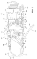
- Figure 1 is a side view of a steering column assembly having a lever in a locking position
- Figure 2 is a side view of the steering column assembly having the lever in an adjusting position
- Figure 3 is a perspective view of an outer jacket with an inner jacket slidably disposed within the outer jacket for telescoping movement;
- Figure 4 is a side view, partly in section, of a first locking device in a first locked position
- Figure 5 is a side view, partly in section, of the first locking device in a first unlocked position
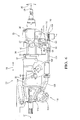
- Figure 6 is a side view of the steering column assembly including an actuator having a motor and a gear box;
- Figure 7 is a side view of the steering column assembly with part of the gear box removed;
- Figure 8 is a side view of a second locking device in a second locked position
- Figure 9 is a side view of the second locking device in a predetermined mid-position
- Figure 10 is a side view of the second locking device in a second unlocked position
- Figure 11 is a graphical representation of the reduction in force to rotate the lever as compared to the prior art.
- a steering column assembly 20 for a vehicle (not shown) is generally shown in Figures 1 and 2.
- the steering column assembly 20 includes a steering column 22 defining a longitudinal axis 24 for providing tilting movement 26 and telescoping movement 28.
- the steering column 22 includes an outer jacket 30 and an inner jacket 32 slidably disposed in the outer jacket 30 along the longitudinal axis 24 for providing the telescoping movement 28.
- the inner jacket 32 includes an upper end 34 with a support member 36 defining a tilt axis 37 is disposed on the upper end 34.
- An upper steering shaft member 38 is coupled to the support member 36 for providing the tilting movement 26.
- a pin 40 is disposed along the tilt axis 37 for coupling the upper steering shaft member 38 to the support member 36.
- a steering wheel (not shown) is coupled to the upper steering shaft member 38 and the driver of the vehicle moves the steering wheel to adjust the steering wheel to the desired position.
- a first locking device 42 is coupled to the steering column 22 and movable between a first locked position 44 securing the steering column 22 for preventing the telescoping movement 28 ( Figures 1 and 4) and a first unlocked position 46 releasing from the steering column 22 for allowing the telescoping movement 28 ( Figures 2 and 5).
- the first locking device 42 defines a predetermined mid-position between the first locked position 44 and the first unlocked position 46.
- the first locking device 42 further defines a pivot axis 48 and includes a bolt 50 disposed along the pivot axis 48 for moving the first locking device 42 between the positions 44, 46 of the first locking device 42.
- a wedge 52 is disposed on the bolt 50 and movable along the pivot axis 48 when the first locking device 42 moves between the positions 44, 46 of the first locking device 42. More specifically, when the first locking device 42 is in the first locked position 44, the wedge 52 engages the inner jacket 32 to prevent the telescoping movement 28. When the first locking device 42 is in the first unlocked position 46, the wedge 52 is spaced from the inner jacket 32 to allow the telescoping movement 28. Wedge devices are well known in the art and will not be discussed further. However it is to be appreciated that any kind of wedge may be used to prevent telescoping movement 28, such as a cam follower device or any other device known to those skilled in the art.
- the first locking device 42 includes a plate 54 having a periphery 56 is coupled to the bolt 50.
- the periphery 56 is spaced from the pivot axis 48 and defines a cavity 58 spaced from the bolt 50.
- the first locking device further includes a lever 60 extends from the plate 54 and spaced from the cavity 58. More specifically, the lever 60 extends from the periphery 56 of the plate 54.
- the lever 60 and the plate 54 are rotatably movable about the pivot axis 48 between the positions 44, 46 of the first locking device 42.
- the lever 60 defines a locking position 62 and an adjusting position 64 such that when the lever 60 rotates about the pivot axis 48 from the locking position 62 to the adjusting position 64, the first locking device 42 moves from the first locked position 44 to the first unlocked position 46.
- an actuator 118 replaces the lever 60.
- the actuator 118 is disposed on the steering column assembly 20 such that the lever 60 is eliminated.
- the actuator 118 is coupled to the plate 54 with the plate 54 rotatably movable about the pivot axis 48 between the positions 44, 46 of the first locking device 42.
- the actuator 118 is further defined as a motor 120 and a gear box 122 with the gear box 122 disposed on the bolt 50 and coupled to the motor 120.
- the motor 120 is coupled to the outer jacket 30. More specifically, a brace 124 is disposed on the outer jacket 30 and the motor 120 is disposed on the brace 124. However it is to be appreciated that the motor 120 may be disposed anywhere on the steering column assembly 20.
- the motor 120 may be an electric motor or any other acceptable type of motor known in the art.
- a drive cable 126 extends between the motor 120 and the gear box 122 for coupling the motor 120 to the gear box 122.
- the gear box 122 includes a worm 128 and a worm gear 130 adjacent one another with the worm gear 130 disposed on the bolt 50.
- the worm 128 and the worm gear 130 are disposed in the gear box 122 with the plate 54 disposed on the worm gear 130.
- the worm gear 130 and the plate 54 may be separate pieces coupled together by welding, fasteners, adhesives or any other way known in the art to couple pieces together.
- the plate 54 and the worm gear 130 may be integrally formed of a homogeneous material.
- the worm 128 and the worm gear 130 each include a plurality of serrations 132 that cooperate with each other for rotating the plate 54 about the pivot axis 48 between the positions 44, 46 of the first locking device 42.
- the drive cable 126 is coupled to the worm 128 such that when the motor 120 is actuated, the drive cable 126 rotates the worm 128 which moves the serrations 132 and rotates the worm gear 130 and the plate 54 about the pivot axis 48 between the positions 44, 46 of the first locking device 42.
- a second locking device 66 is coupled to the steering column 22 and moveable between a second locked position 68 securing the steering column 22 for preventing the tilting movement 26 ( Figures 1 and 8) and a second unlocked position 70 releasing from the steering column 22 for allowing the tilting movement 26 ( Figures 2 and 10).
- Figure 9 shows the second locking device 66 in the predetermined mid-position.
- the second locking device 66 includes a body portion 72 having an arm 74 extending away from the body portion 72. More specifically, the body portion 72 extends along the longitudinal axis 24 and the arm 74 extends radially away from the longitudinal axis 24.
- the arm 74 includes a front side 76 and a back side 78 spaced from each other and having a stop surface 80 disposed on the front side 76.
- the body portion 72 includes an angled surface 82 adjacent to the front side 76 of the arm 74.
- a return spring (not shown) may be coupled to the body portion 72 for continuously biasing the second locking device 66 in the second locked position.
- a first shoe 84 and a second shoe 86 are disposed on the steering column 22 with each having cooperating teeth 88 for preventing the tilting movement 26 when the teeth 88 of the first and second shoe 86 are engaged.
- the first shoe 84 includes a first side 90 and a second side 92 opposing one another with the first side 90 having the teeth 88.
- the first shoe 84 is continuously biased toward the body portion 72 of the second locking device 66 by a spring (not shown).
- the second side 92 of the first shoe 84 includes a raised portion 94 for abutting the angled surface 82 of the body portion 72 such that when the body portion 72 moves, the raised portion 94 moves along the angled surface 82 to engage or disengage the teeth 88 of the first shoe 84 with the teeth 88 of the second shoe 86. More specifically, when the second locking device 66 moves to the second unlocked position 70, the body portion 72 moves along the longitudinal axis 24 and moves along the tilting axis 37 such that the raised portion 94 of the first shoe 84 moves along the angled surface 82 of the body portion 72 to disengage the teeth 88 of the first and second shoes 84, 86.
- the first shoe 84 and the second shoe 86 are well known in the art and will not be discussed further.
- a cable 96 extends between the first locking device 42 and the second locking device 66.
- the cable 96 includes a first end 98 coupled to the first locking device 42 and a second end 100 coupled to the second locking device 66.
- the first end 98 of the cable 96 may be coupled to the periphery 56 of the plate 54 such that when the first locking device 42 moves, the first end 98 of the cable 96 moves without pulling the second end 100 of the cable 96.
- a protrusion 102 is disposed on the first end 98 of the cable 96. More specifically, the protrusion 102 is disposed in the cavity 58 of the plate 54 for securing the first end 98 of the cable 96 to the first locking device 42.
- a conduit 104 is disposed about the cable 96 for supporting the cable 96.
- the conduit 104 is spaced from the first end 98 and the second end 100 of the cable 96 with the cable 96 slidable in the conduit 104.
- At least one bracket 106 may be disposed on the steering column 22 for supporting the cable 96.
- One bracket 106 may be disposed on the outer jacket 30 and another bracket 106 may be disposed on the upper steering shaft member 38. However it is to be appreciated that the bracket 106 may be disposed anywhere on the steering column 22.
- a mechanism is coupled to the cable 96 for delaying release of the second locking device 66 from the steering column 22 until the first locking device 42 moves to the predetermined mid-position.
- the delay in the release of the second locking device 66 reduces the overall force to rotate the lever 60 from the locking position 62 to the adjusting position 64.
- the mechanism allows for a more uniform lever load when delaying release of the second locking device 66 from the steering column 22 until the first locking device 42 moves to the predetermined mid-position.
- Figure 11 shows a graphical interpretation of the reduction in the force as compared to the prior art.
- the mechanism is disposed adjacent at least one of the first end 98 and the second end 100 of the cable 96.
- the mechanism may include some of the features of the first locking device 42 such that when the first locking device 42 moves from the first locked position 44 to the first unlocked position 46, the first end 98 of the cable 96 moves without pulling the second end 100 of the cable 96.
- the mechanism may be further defined as an extension 108 connected to the second end 100 of the cable 96 and extending away from the second locking device 66 to define a length (L) and a distal end 110.
- the extension 108 and the cable 96 are supported by the arm 74 of the second locking device 66.
- the extension 108 moves through the arm 74 along the length (L) until the first locking device 42 moves to the predetermined mid-position and the distal end 110 engages the stop surface 80 (see Figure 9).
- the extension 108 moves relative to the second locking device 66 while the second locking device 66 remains in the second locked position for delaying release of the second locking device 66 from the steering column 22 until the first locking device 42 rotates to the predetermined mid-position.
- the delay in the release of the second locking device 66 reduces the overall force to rotate the lever 60 from the locking position 62 to the adjusting position 64.
- the mechanism allows for a more uniform lever load when delaying release of the second locking device 66 from the steering column 22 until the first locking device 42 moves to the predetermined mid-position.
- Figure 11 shows a graphical interpretation of the reduction in the force as compared to the prior art.
- the mechanism can be any suitable configuration so long as there is a delay in release of the second locking device 66 until the first locking device 42 rotates to the predetermined mid-position.
- the mechanism may be further defined as a cam 114 or a biasing device as discussed below.
- the extension 108 and the second end 100 of the cable 96 are integrally formed of a homogeneous material.
- the second locking device 66 moves back to the second locking position 62 by the return spring of the body portion 72, and the cable 96 is strong enough to push back through the conduit 104 and move the extension 108 back to the length (L) from the second locking device 66.
- the mechanism may be further defined as the biasing device disposed about the extension 108 along the length (L) between the stop surface 80 and the distal end 110 for continuously biasing the distal end 110 away from the stop surface 80.
- the biasing device may be further defined as a coil spring 112 disposed about the extension 108 along the length (L) between the stop surface 80 and the distal end 110 for continuously biasing the distal end 110 away from the stop surface 80.
- the coil spring 112 continuously biases the distal end 110 away from the stop surface 80 to take up the length (L) to prevent the cable 96 from rattling within the conduit 104.
- the distal end 110 of the extension 108 moves toward the arm 74 which compresses the coil spring 112 against the stop surface 80 of the arm 74.
- the coil spring 112 may be fully compressed or only partially compressed when the second locking device 66 disengages the teeth 88 of the first and second shoes 84, 86.
- the amount the coil spring 112 is compressed depends on the shape of the distal end 110 and/or the length (L) of the extension 108.
- the distal end 110 could have a t-shaped configuration or define a cavity 58, in which the coil spring 112 will compress a pre-determined amount until the distal end 110 engages the stop surface 80.
- the biasing device is optional.
- the mechanism may be further defined as the cam 114 having an arcuate profile defining a variable movement of the cable 96 as the first locking device 42 moves from the first locked position 44 to the predetermined mid-position.
- the cam 114 may be disposed adjacent the cavity 58 of the plate 54.
- the cam 114 defines a recess 116 adjacent the cavity 58 of the plate 54 for maintaining the cable 96 within the recess 116.
- the cam 114 and the plate 54 are integrally formed of a homogeneous material such that the cam 114 rotates about the pivot axis 48 during movement of the first locking device 42 between the positions 44, 46 of the first locking device 42.
- the arcuate profile of the cam 114 may be steep, shallow, or any acceptable profile to increase or decrease the variable movement of the cable 96 as the first locking device 42 moves from the first locked position 44 to the predetermined mid-position. However it is to be appreciated that when the first locking device 42 moves from the first locked position 44 to the predetermined mid-position, the cam 114 may slow the pulling of the cable 96.
- the lever 60 is rotated from the locking position 62 to the adjusting position 64.
- the first locking device 42 moves from the first locked position 44 to the predetermined mid-position.
- the wedge 52 of the first locking device 42 moves along the pivot axis 48 away from the inner jacket 32 to allow the telescoping movement 28 (as shown in Figure 5).
- the cam 114 and the plate 54 rotate about the pivot axis 48 which moves the first end 98 of the cable 96 without moving the second locking device 66 to the second unlocked position 70.
- the first end 98 of the cable 96 moves the second end 100 of the cable 96 which also moves the extension 108 and the distal end 110 to engage the stop surface 80 of the arm 74 (as shown in Figure 9).
- the coil spring 112 is disposed between the distal end 110 and the stop surface 80 and the distal end 110 and/or the length of the extension 108 is design such that the coil spring 112 is to be fully compressed, then the fully compressed coil spring 112 would abut the stop surface 80 instead of the distal end 110.
- the distal end 110 moves the arm 74 and ultimately the body portion 72 of the second locking device 66.
- the body portion 72 of the second locking device 66 moves along the longitudinal axis 24 and along the tilt axis 37 while the raised portion 94 of the first shoe 84 moves along the angled surface 82 of the body portion 72 to disengaged the teeth 88 from the second shoe 86 for allowing the tilting movement 26 (as shown in Figure 10).
- the lever 60 is rotated about the pivot axis 48 from the adjusting position 64 to the locking position 62.
- the first locking device 42 moves from the first unlocked position 46 to the first locked position 44 and the wedge 52 of the first locking device 42 moves along the pivot axis 48 and engages the inner jacket 32 to prevent the telescoping movement 28 (as shown in Figure 4).
- the cam 114 and the plate 54 rotate about the pivot axis 48 which moves the first end 98 of the cable 96. As the first end 98 of the cable 96 moves, the extension 108 moves back through the arm 74 and the distal end 110 moves away from the stop surface 80 of the arm 74.
- the coil spring 112 is disposed between the distal end 110 and the stop surface 80 and the coil spring 112 decompresses and continuously biases the distal end 110 away from the stop surface 80.
- the arm 74 and the body portion 72 move back along the longitudinal axis 24 and along the tilt axis 37 by the return spring of the second locking device 66.
- the raised portion 94 of the first shoe 84 moves along the angled surface 82 of the body portion 72 to engaged the teeth 88 of the second shoe 86 for preventing the tilting movement 26.
Landscapes
- Engineering & Computer Science (AREA)
- Chemical & Material Sciences (AREA)
- Combustion & Propulsion (AREA)
- Transportation (AREA)
- Mechanical Engineering (AREA)
- Lock And Its Accessories (AREA)
- Steering Controls (AREA)
Applications Claiming Priority (1)
| Application Number | Priority Date | Filing Date | Title |
|---|---|---|---|
| US11/546,611 US20080141815A1 (en) | 2006-10-12 | 2006-10-12 | Steering column assembly for a vehicle |
Publications (1)
| Publication Number | Publication Date |
|---|---|
| EP1911657A2 true EP1911657A2 (de) | 2008-04-16 |
Family
ID=38686622
Family Applications (1)
| Application Number | Title | Priority Date | Filing Date |
|---|---|---|---|
| EP07118059A Withdrawn EP1911657A2 (de) | 2006-10-12 | 2007-10-08 | Lenksäulenanordnung für ein Fahrzeug |
Country Status (2)
| Country | Link |
|---|---|
| US (1) | US20080141815A1 (de) |
| EP (1) | EP1911657A2 (de) |
Cited By (1)
| Publication number | Priority date | Publication date | Assignee | Title |
|---|---|---|---|---|
| EP1955922A3 (de) * | 2007-02-09 | 2009-04-22 | Delphi Technologies, Inc. | Lenksäulenanordnung |
Families Citing this family (5)
| Publication number | Priority date | Publication date | Assignee | Title |
|---|---|---|---|---|
| US7770487B2 (en) * | 2007-03-30 | 2010-08-10 | Nissan Technical Center North America, Inc. | Vehicle steering column structure |
| US10023223B2 (en) * | 2016-06-03 | 2018-07-17 | Steering Solutions Ip Holding Corporation | Steering column assembly |
| US10807630B2 (en) | 2018-11-29 | 2020-10-20 | Steering Solutions Ip Holding Corporation | Steering column having an energy absorption assembly |
| CN110507342B (zh) * | 2019-08-28 | 2023-03-31 | 东软医疗系统股份有限公司 | 解锁驱动装置及医疗影像设备 |
| US11370472B2 (en) * | 2019-12-12 | 2022-06-28 | Mahindra N.A. Tech Center | Steering column tilt lock |
Family Cites Families (26)
| Publication number | Priority date | Publication date | Assignee | Title |
|---|---|---|---|---|
| US3285090A (en) * | 1965-05-20 | 1966-11-15 | Gen Motors Corp | Adjustable steering column |
| EP0114810A1 (de) * | 1982-07-21 | 1984-08-08 | J. I. Case Company | Neig- und ausziehbare lenkradanordnung |
| SE459331B (sv) * | 1985-03-07 | 1989-06-26 | Johansson Claes Verkstads | Laengd- och lutningsinstaellbar rattstaang foer fordon |
| FR2588047B1 (fr) * | 1985-09-30 | 1988-01-08 | Peugeot Cycles | Dispositif de fixation pour une piece tubulaire en particulier pour une colonne de direction de vehicule |
| US4753121A (en) * | 1987-05-05 | 1988-06-28 | Trw Inc. | Tilt-telescope steering column |
| US4793204A (en) * | 1987-11-25 | 1988-12-27 | Douglas Components Corporation | Tilt and telescope steering column having a single control |
| US5722299A (en) * | 1994-06-30 | 1998-03-03 | Fuji Kiko Co., Ltd. | Adjustable steering column assembly for a vehicle |
| US5820163A (en) * | 1996-07-08 | 1998-10-13 | Ford Global Technologies, Inc. | Tilting, telescoping and energy absorbing steering column |
| DE19643203A1 (de) * | 1996-10-19 | 1998-04-23 | Supervis Ets | Vorrichtung an einer Lenksäule für Kraftfahrzeuge zur Längen- und/oder Höhen- bzw. Neigungsverstellung |
| US5979265A (en) * | 1997-09-11 | 1999-11-09 | Mando Machinery Corporation | Tilting and telescopic structure for steering columns |
| US6035739A (en) * | 1998-03-20 | 2000-03-14 | General Motors Corporation | Adjustable steering column for motor vehicle |
| US6244128B1 (en) * | 1998-09-25 | 2001-06-12 | Joseph C. Spencer | Steering wheel impact positioning system |
| US6205882B1 (en) * | 1999-04-08 | 2001-03-27 | Daimlerchrysler Corporation | Tilt release system for a steering column |
| US6223620B1 (en) * | 1999-04-08 | 2001-05-01 | Daimlerchrysler Corporation | Tilt release system for a steering column |
| US6272945B1 (en) * | 1999-04-08 | 2001-08-14 | Daimlerchrysler Corporation | Tilt release system for a steering column |
| US6237439B1 (en) * | 1999-09-09 | 2001-05-29 | Visteon Global Technologies, Inc. | Single release lever for steering column tilt and telescope |
| JP3431886B2 (ja) * | 2000-07-07 | 2003-07-28 | 株式会社山田製作所 | ステアリング位置調整装置 |
| KR100377435B1 (ko) * | 2000-12-01 | 2003-03-26 | 주식회사 만도 | 차량용 스티어링 컬럼의 위치조절장치 |
| JP3886766B2 (ja) * | 2001-01-11 | 2007-02-28 | 富士機工株式会社 | チルト・テレスコピック式ステアリングコラム装置 |
| US6640661B2 (en) * | 2001-12-05 | 2003-11-04 | Daimlerchrysler Corporation | Tilt steering wheel |
| US6460427B1 (en) * | 2002-01-28 | 2002-10-08 | Ford Global Technologies, Inc. | Adjustment linkage for tilting and telescoping a steering column assembly |
| US7331608B2 (en) * | 2002-06-27 | 2008-02-19 | Delphi Technologies, Inc. | Electrically actuated steering column mechanism |
| US7090250B2 (en) * | 2002-09-25 | 2006-08-15 | Fuji Kiko Co., Ltd. | Steering system with tilt control |
| JP2004262433A (ja) * | 2003-02-14 | 2004-09-24 | Nsk Ltd | ステアリングコラム装置 |
| JP2005014681A (ja) * | 2003-06-24 | 2005-01-20 | Nsk Ltd | 車両用ステアリングコラム装置 |
| US20070068310A1 (en) * | 2005-09-01 | 2007-03-29 | Koji Arihara | Steering column device for steering wheel of vehicle |
-
2006
- 2006-10-12 US US11/546,611 patent/US20080141815A1/en not_active Abandoned
-
2007
- 2007-10-08 EP EP07118059A patent/EP1911657A2/de not_active Withdrawn
Cited By (1)
| Publication number | Priority date | Publication date | Assignee | Title |
|---|---|---|---|---|
| EP1955922A3 (de) * | 2007-02-09 | 2009-04-22 | Delphi Technologies, Inc. | Lenksäulenanordnung |
Also Published As
| Publication number | Publication date |
|---|---|
| US20080141815A1 (en) | 2008-06-19 |
Similar Documents
| Publication | Publication Date | Title |
|---|---|---|
| EP3519276B1 (de) | Lenkanordnung mit formschluss und energieabsorption und pyrotechnischem aktuator | |
| EP1911657A2 (de) | Lenksäulenanordnung für ein Fahrzeug | |
| US5009120A (en) | Manual control for adjustable steering column | |
| CN101096187A (zh) | 旋转式调节机构 | |
| US20130319163A1 (en) | Steering Column Assembly | |
| US7367589B2 (en) | Collapsible steering assembly with a stationary reaction surface | |
| US6272945B1 (en) | Tilt release system for a steering column | |
| US7743681B2 (en) | Steering column assembly having an actuation mechanism for telescoping and tilting movement | |
| US11845487B2 (en) | Steering column breakaway and energy absorption apparatus | |
| US7798037B2 (en) | Wedge arm positive rake lock | |
| EP1955922A2 (de) | Lenksäulenanordnung | |
| CN113891826B (zh) | 转向柱防旋转装置 | |
| JP2003506258A (ja) | 駐車ブレーキのための作動装置 | |
| JP4234384B2 (ja) | 調整自在のステアリングコラム用クランプ止め機構 | |
| KR20190068152A (ko) | 자동차용 스티어링 컬럼의 텔레스코프 장치 | |
| EP1048547A2 (de) | Lenksäuleneinheit | |
| WO2018160788A1 (en) | Steering column telescope travel stop | |
| CN113939439B (zh) | 转向柱强制锁定驱动机构 | |
| US7770975B2 (en) | Locking device | |
| US11285989B2 (en) | Steering column for a motor vehicle | |
| KR100475922B1 (ko) | 자동차의 스티어링 컬럼 | |
| JP2000289628A (ja) | チルト・テレスコ式ステアリング装置 | |
| EP4017782B1 (de) | Formschlüssige arretierung einer teleskopischen lenksäule und anfahrsicherung | |
| US20080282834A1 (en) | Bowden Cable Actuation System |
Legal Events
| Date | Code | Title | Description |
|---|---|---|---|
| PUAI | Public reference made under article 153(3) epc to a published international application that has entered the european phase |
Free format text: ORIGINAL CODE: 0009012 |
|
| AK | Designated contracting states |
Kind code of ref document: A2 Designated state(s): AT BE BG CH CY CZ DE DK EE ES FI FR GB GR HU IE IS IT LI LT LU LV MC MT NL PL PT RO SE SI SK TR |
|
| AX | Request for extension of the european patent |
Extension state: AL BA HR MK RS |
|
| STAA | Information on the status of an ep patent application or granted ep patent |
Free format text: STATUS: THE APPLICATION IS DEEMED TO BE WITHDRAWN |
|
| 18D | Application deemed to be withdrawn |
Effective date: 20100501 |