EP1910000B1 - Werkzeugrevolver mit einem drehantreibbaren werkzeug an der stirnseite - Google Patents
Werkzeugrevolver mit einem drehantreibbaren werkzeug an der stirnseite Download PDFInfo
- Publication number
- EP1910000B1 EP1910000B1 EP06705923A EP06705923A EP1910000B1 EP 1910000 B1 EP1910000 B1 EP 1910000B1 EP 06705923 A EP06705923 A EP 06705923A EP 06705923 A EP06705923 A EP 06705923A EP 1910000 B1 EP1910000 B1 EP 1910000B1
- Authority
- EP
- European Patent Office
- Prior art keywords
- tool
- machine
- carrier
- hollow shaft
- turret
- Prior art date
- Legal status (The legal status is an assumption and is not a legal conclusion. Google has not performed a legal analysis and makes no representation as to the accuracy of the status listed.)
- Ceased
Links
Images

Classifications
-
- B—PERFORMING OPERATIONS; TRANSPORTING
- B23—MACHINE TOOLS; METAL-WORKING NOT OTHERWISE PROVIDED FOR
- B23B—TURNING; BORING
- B23B3/00—General-purpose turning-machines or devices, e.g. centre lathes with feed rod and lead screw; Sets of turning-machines
- B23B3/16—Turret lathes for turning individually-chucked workpieces
- B23B3/167—Turret lathes for turning individually-chucked workpieces lathe with two or more toolslides carrying turrets
- B23B3/168—Arrangements for performing other machining operations, e.g. milling, drilling
-
- B—PERFORMING OPERATIONS; TRANSPORTING
- B23—MACHINE TOOLS; METAL-WORKING NOT OTHERWISE PROVIDED FOR
- B23B—TURNING; BORING
- B23B29/00—Holders for non-rotary cutting tools; Boring bars or boring heads; Accessories for tool holders
- B23B29/24—Tool holders for a plurality of cutting tools, e.g. turrets
- B23B29/242—Turrets, without description of the angular positioning device
-
- B—PERFORMING OPERATIONS; TRANSPORTING
- B23—MACHINE TOOLS; METAL-WORKING NOT OTHERWISE PROVIDED FOR
- B23B—TURNING; BORING
- B23B29/00—Holders for non-rotary cutting tools; Boring bars or boring heads; Accessories for tool holders
- B23B29/24—Tool holders for a plurality of cutting tools, e.g. turrets
- B23B29/32—Turrets adjustable by power drive, i.e. turret heads
- B23B29/323—Turrets with power operated angular positioning devices
-
- B—PERFORMING OPERATIONS; TRANSPORTING
- B23—MACHINE TOOLS; METAL-WORKING NOT OTHERWISE PROVIDED FOR
- B23Q—DETAILS, COMPONENTS, OR ACCESSORIES FOR MACHINE TOOLS, e.g. ARRANGEMENTS FOR COPYING OR CONTROLLING; MACHINE TOOLS IN GENERAL CHARACTERISED BY THE CONSTRUCTION OF PARTICULAR DETAILS OR COMPONENTS; COMBINATIONS OR ASSOCIATIONS OF METAL-WORKING MACHINES, NOT DIRECTED TO A PARTICULAR RESULT
- B23Q5/00—Driving or feeding mechanisms; Control arrangements therefor
- B23Q5/02—Driving main working members
- B23Q5/04—Driving main working members rotary shafts, e.g. working-spindles
-
- B—PERFORMING OPERATIONS; TRANSPORTING
- B24—GRINDING; POLISHING
- B24B—MACHINES, DEVICES, OR PROCESSES FOR GRINDING OR POLISHING; DRESSING OR CONDITIONING OF ABRADING SURFACES; FEEDING OF GRINDING, POLISHING, OR LAPPING AGENTS
- B24B27/00—Other grinding machines or devices
- B24B27/0061—Other grinding machines or devices having several tools on a revolving tools box
-
- B—PERFORMING OPERATIONS; TRANSPORTING
- B23—MACHINE TOOLS; METAL-WORKING NOT OTHERWISE PROVIDED FOR
- B23Q—DETAILS, COMPONENTS, OR ACCESSORIES FOR MACHINE TOOLS, e.g. ARRANGEMENTS FOR COPYING OR CONTROLLING; MACHINE TOOLS IN GENERAL CHARACTERISED BY THE CONSTRUCTION OF PARTICULAR DETAILS OR COMPONENTS; COMBINATIONS OR ASSOCIATIONS OF METAL-WORKING MACHINES, NOT DIRECTED TO A PARTICULAR RESULT
- B23Q2220/00—Machine tool components
- B23Q2220/002—Tool turrets
-
- Y—GENERAL TAGGING OF NEW TECHNOLOGICAL DEVELOPMENTS; GENERAL TAGGING OF CROSS-SECTIONAL TECHNOLOGIES SPANNING OVER SEVERAL SECTIONS OF THE IPC; TECHNICAL SUBJECTS COVERED BY FORMER USPC CROSS-REFERENCE ART COLLECTIONS [XRACs] AND DIGESTS
- Y10—TECHNICAL SUBJECTS COVERED BY FORMER USPC
- Y10T—TECHNICAL SUBJECTS COVERED BY FORMER US CLASSIFICATION
- Y10T29/00—Metal working
- Y10T29/51—Plural diverse manufacturing apparatus including means for metal shaping or assembling
- Y10T29/5104—Type of machine
- Y10T29/5109—Lathe
- Y10T29/5114—Lathe and tool
-
- Y—GENERAL TAGGING OF NEW TECHNOLOGICAL DEVELOPMENTS; GENERAL TAGGING OF CROSS-SECTIONAL TECHNOLOGIES SPANNING OVER SEVERAL SECTIONS OF THE IPC; TECHNICAL SUBJECTS COVERED BY FORMER USPC CROSS-REFERENCE ART COLLECTIONS [XRACs] AND DIGESTS
- Y10—TECHNICAL SUBJECTS COVERED BY FORMER USPC
- Y10T—TECHNICAL SUBJECTS COVERED BY FORMER US CLASSIFICATION
- Y10T29/00—Metal working
- Y10T29/51—Plural diverse manufacturing apparatus including means for metal shaping or assembling
- Y10T29/5152—Plural diverse manufacturing apparatus including means for metal shaping or assembling with turret mechanism
- Y10T29/5154—Plural diverse manufacturing apparatus including means for metal shaping or assembling with turret mechanism tool turret
- Y10T29/5155—Rotary tool holder
-
- Y—GENERAL TAGGING OF NEW TECHNOLOGICAL DEVELOPMENTS; GENERAL TAGGING OF CROSS-SECTIONAL TECHNOLOGIES SPANNING OVER SEVERAL SECTIONS OF THE IPC; TECHNICAL SUBJECTS COVERED BY FORMER USPC CROSS-REFERENCE ART COLLECTIONS [XRACs] AND DIGESTS
- Y10—TECHNICAL SUBJECTS COVERED BY FORMER USPC
- Y10T—TECHNICAL SUBJECTS COVERED BY FORMER US CLASSIFICATION
- Y10T29/00—Metal working
- Y10T29/51—Plural diverse manufacturing apparatus including means for metal shaping or assembling
- Y10T29/5176—Plural diverse manufacturing apparatus including means for metal shaping or assembling including machining means
-
- Y—GENERAL TAGGING OF NEW TECHNOLOGICAL DEVELOPMENTS; GENERAL TAGGING OF CROSS-SECTIONAL TECHNOLOGIES SPANNING OVER SEVERAL SECTIONS OF THE IPC; TECHNICAL SUBJECTS COVERED BY FORMER USPC CROSS-REFERENCE ART COLLECTIONS [XRACs] AND DIGESTS
- Y10—TECHNICAL SUBJECTS COVERED BY FORMER USPC
- Y10T—TECHNICAL SUBJECTS COVERED BY FORMER US CLASSIFICATION
- Y10T82/00—Turning
- Y10T82/25—Lathe
- Y10T82/2508—Lathe with tool turret
Definitions
- the invention relates to a machine tool with a tool turret according to the preamble of claim 1 (see, for example, US Pat. US-5,125,142-A ). From the DE 298 07 842 U1 is a tool turret with cutting tools for turning and drivable tools for drilling or grinding known.
- a tool turret with direct drive for the pivoting movement is from the DE 199 19 553 A1 known.
- the tools are arranged in a turret disk.
- the driven tools are driven through an angle gear through the turret disk. Because of the limited space available, the maximum drive power for the tools and thus the size of usable grinding tools is significantly limited.
- the core idea of the invention is to arrange the driven tool on the front side of the tool carrier.
- the drive takes place without deflection and mechanical intermediate links, such as bevel gear, are passed through the tool carrier and the limited space in the Tool carriers have no influence on the design of the drive.
- the driven tool is not moved during the pivoting movements of the tool carrier. This allows higher accelerations during tool change and shortens the time required for machining a workpiece.
- the tool carrier is rotatably connected to a hollow shaft.
- the spindle is mounted for the tool drive.
- the hollow shaft receives a ring motor for driving the pivoting movements of the tool carrier.
- the inner diameter of the hollow shaft is selected so that the drive motor for the tool can be arranged in the interior of the hollow shaft.
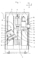
- Fig. 1 shows a machine tool 1, in which not essential to the invention details of the workpiece feed, the drive, the controller and the housing are not shown.
- the machine tool 1 described is particularly suitable for machining wave-shaped workpieces 7. These are clamped in the workpiece holding device 29, consisting of the motor spindle 8 and the tailstock 9 and set in rotation.
- the two tool turrets 10 and 11 are guided on the machine frame 2 in two mutually orthogonal directions (X and Z axis) movable.
- vertical guides 3 are provided on the machine frame 2 for the vertical slide 4 and these in turn carry guides 12 for the horizontal slide 5.
- the tool carrier 6 are rotatably mounted about a pivot axis 13.
- the tool carriers 6 receive stationary tools 14, in particular for turning.
- the tool 16 is designed as a conical grinding wheel. Therefore, a pivot axis 17 is provided on the tool turret 11, so that the spindle of the tool 16 relative to the workpiece 7, the cone angle can be inclined accordingly. With this arrangement, conical surfaces 18 can also be machined on the workpiece 8.
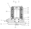
- Fig. 2 shows the tool turret 10, partially cut.
- the housing 19 may be machine-mounted, or as in Fig. 1 shown to be arranged on a carriage.
- the hollow shaft 21 is mounted with the bearings 20, 20 '.
- rotor 22 is attached on the outside of the composite of individual magnets rotor 22 is attached. This is associated with an electrical windings exhibiting stator 23 in the housing 19.
- the tool carrier 6 is firmly screwed to the hollow shaft 21.
- Rotor 22 and stator 23 together form a ring motor, which serves as a drive for the pivoting movements of the tool carrier 6.
- the tool carrier 6 is designed as a disc which receives tools 14, in particular for turning, on its circumferential surface.
- the tool 15 is arranged on the end face of the tool carrier 6.
- the spindle 25 is connected through the hollow shaft 21 through the shaft 27 directly to the motor 28.
- the limited space in the tool carrier 6 no longer has any influence on the design of the drive.
- the driven tool 15 is not moved during the pivoting movements of the tool carrier 6. This allows higher accelerations during tool change and enables shorter cycle times for the machining of the workpieces 7.
- the inner diameter of the hollow shaft 21 is dimensioned so that the motor 28 is located to drive the tool 16 in the interior of the hollow shaft 21 space.
- spindle 25 for the tool 15 is connected directly to the motor 28.
- Housing 19, tool carrier 6 and rotary actuator with ring motor are analogous to the description of the embodiment according to Fig. 2 arranged.
Landscapes
- Engineering & Computer Science (AREA)
- Mechanical Engineering (AREA)
- Turning (AREA)
- Automatic Tool Replacement In Machine Tools (AREA)
- Finish Polishing, Edge Sharpening, And Grinding By Specific Grinding Devices (AREA)
Description
- Die Erfindung betrifft eine Werkzeugmaschine mit einem Werkzeugrevolver nach dem Oberbegriff von Anspruch 1 (siehe, z.B.,
US- 5,125,142-A ). Aus derDE 298 07 842 U1 ist ein Werkzeugrevolver mit Schneidwerkzeugen zum Drehen und antreibbaren Werkzeugen zum Bohren oder Schleifen bekannt. - Ein Werkzeugrevolver mit Direktantrieb für die Schwenkbewegung ist aus der
DE 199 19 553 A1 bekannt. Bei beiden Werkzeugrevolvern sind die Werkzeuge in einer Revolverscheibe angeordnet. Die angetriebenen Werkzeuge werden über ein Winkelgetriebe durch die Revolverscheibe hindurch angetrieben. Wegen der begrenzten Platzverhältnisse ist die maximale Antriebsleistung für die Werkzeuge und damit auch die Größe von einsetzbaren Schleifwerkzeugen deutlich eingeschränkt. - Es besteht daher die Aufgabe, eine Werkzeugmaschine mit einem Werkzeugrevolver so auszubilden, dass der Antrieb für die Werkzeuge bei verringertem Platzbedarf kostengünstig und einfach ausgeführt werden kann.
- Gelöst wird diese Aufgabe mit einer Werkzeugmaschine nach Anspruch 1. Vorteilhafte Ausgestaltungen sind den jeweiligen Unteransprüchen entnehmbar.
- Der Kerngedanke der Erfindung besteht darin, das angetriebene Werkzeug an der Stirnseite des Werkzeugträgers anzuordnen. Dabei erfolgt der Antrieb ohne Umlenkung und mechanische Zwischenglieder, wie z.B. Winkelgetriebe, durch den Werkzeugträger hindurchgeführt werden und die begrenzten Platzverhältnisse im Werkzeugträger haben keinen Einfluss mehr auf die Auslegung des Antriebs. Zudem wird das angetriebene Werkzeug bei den Schwenkbewegungen des Werkzeugträgers nicht mitbewegt. Dies erlaubt höhere Beschleunigungen beim Werkzeugwechsel und verkürzt die für die Bearbeitung eines Werkstücks erforderliche Zeit.
- Bei einer vorteilhaften Ausführung ist der Werkzeugträger mit einer Hohlwelle drehfest verbunden. Im Innern der Hohlwelle ist die Spindel für den Werkzeugantrieb gelagert. An ihrer Außenseite nimmt die Hohlwelle einen Ringmotor zum Antrieb für die Schwenkbewegungen des Werkzeugträgers auf. Bei einer weiteren Ausführung ist der Innendurchmesser der Hohlwelle so gewählt, dass der Antriebsmotor für das Werkzeug im Inneren der Hohlwelle angeordnet werden kann.
- Im Folgenden wird die Erfindung an Hand von Ausführungsbeispielen näher erläutert.
- Fig. 1
- zeigt eine Werkzeugmaschine mit zwei Werkzeugrevolvern
- Fig. 2
- zeigt einen Werkzeugrevolver teilweise geschnitten
- Fig. 3
- zeigt einen Werkzeugrevolver mit in der Hohlwelle angeordnetem Antriebsmotor teilweise geschnitten
-
Fig. 1 zeigt eine Werkzeugmaschine 1, bei welcher nicht erfindungswesentliche Details der Werkstückzuführung, des Antriebs, der Steuerung und des Gehäuses nicht dargestellt sind. Die beschriebene Werkzeugmaschine 1 eignet sich insbesondere zur Bearbeitung wellenförmiger Werkstücke 7. Diese werden in der Werkstückhaltevorrichtung 29, bestehend aus der Motorspindel 8 und dem Reitstock 9 eingespannt und in Rotation versetzt. Die beiden Werkzeugrevolver 10 und 11 sind am Maschinengestell 2 in zwei zueinander orthogonalen Richtungen (X- und Z-Achse) beweglich geführt. Dazu sind am Maschinengestell 2 vertikale Führungen 3 für die Vertikalschlitten 4 vorgesehen und diese tragen ihrerseits Führungen 12 für die Horizontalschlitten 5. In den Horizontalschlitten 5 sind die Werkzeugträger 6 um eine Schwenkachse 13 drehbar gelagert. Die Werkzeugträger 6 nehmen feststehende Werkzeuge 14, insbesondere zum Drehen, auf. An den Stirnseiten der Werkzeugträger 6 sind angetriebene Werkzeuge 15, 16 angeordnet. Das Werkzeug 16 ist als konische Schleifscheibe ausgeführt. Daher ist am Werkzeugrevolver 11 eine Schwenkachse 17 vorgesehen, damit die Spindel des Werkzeugs 16 gegenüber dem Werkstück 7 dem Konuswinkel entsprechend geneigt werden kann. Mit dieser Anordnung lassen sich ebenso konische Flächen 18 am Werkstück 8 bearbeiten. -
Fig. 2 zeigt den Werkzeugrevolver 10, teilweise geschnitten. Das Gehäuse 19 kann maschinenfest, oder wie inFig. 1 dargestellt, auf einem Schlitten angeordnet sein. Im Gehäuse 19 ist mit den Lagern 20, 20' die Hohlwelle 21 gelagert. Darauf ist außen der aus Einzelmagneten zusammengesetzte Rotor 22 befestigt. Diesem ist im Gehäuse 19 ein elektrische Windungen aufweisender Stator 23 zugeordnet. Der Werkzeugträger 6 ist fest mit der Hohlwelle 21 verschraubt. Rotor 22 und Stator 23 bilden zusammen einen Ringmotor, der als Antrieb für die Schwenkbewegungen des Werkzeugträgers 6 dient. Der Werkzeugträger 6 ist als Scheibe ausgeführt, die an ihrer Umfangsfläche Werkzeuge 14, insbesondere zum Drehen, aufnimmt. Im Zentrum des Werkzeugträgers 6 befinden sich die Lager 24, 24' für die Spindel 25 des angetriebenen Werkzeugs 15. Das Werkzeug 15 ist an der Stirnseite des Werkzeugträgers 6 angeordnet. Die Spindel 25 ist durch die Hohlwelle 21 hindurch über die Welle 27 direkt mit dem Motor 28 verbunden. Bei dieser Anordnung haben die begrenzten Platzverhältnisse im Werkzeugträger 6 keinen Einfluss mehr auf die Auslegung des Antriebs. Zudem wird das angetriebene Werkzeug 15 bei den Schwenkbewegungen des Werkzeugträgers 6 nicht mitbewegt. Dies erlaubt höhere Beschleunigungen beim Werkzeugwechsel und ermöglicht kürzere Zykluszeiten für die für die Bearbeitung der Werkstücke 7. - Bei der Ausführung nach
Fig. 3 ist der Innendurchmesser der Hohlwelle 21 so dimensioniert, dass der Motor 28 zum Antrieb des Werkzeugs 16 im Inneren der Hohlwelle 21 Platz findet. Bei dieser platzsparenden Anordnung ist Spindel 25 für das Werkzeug 15 direkt mit dem Motor 28 verbunden. Gehäuse 19, Werkzeugträger 6 und Schwenkantrieb mit Ringmotor sind analog zur Beschreibung der Ausführung nachFig. 2 angeordnet. -
- 1
- Werkzeugmaschine
- 2
- Maschinengestell
- 3
- Führung
- 4
- Vertikalschlitten
- 5
- Horizontalschlitten
- 6
- Werkzeugträger
- 7
- Werkstück
- 8
- Motorspindel
- 9
- Reitstock
- 10
- Werkzeugrevolver
- 11
- Werkzeugrevolver
- 12
- Führung
- 13
- Schwenkachse
- 14
- Werkzeug
- 15
- Werkzeug
- 16
- Werkzeug
- 17
- Schwenkachse
- 18
- konische Fläche
- 19
- Gehäuse
- 20 20'
- Lager
- 21
- Hohlwelle
- 22
- Rotor
- 23
- Stator
- 24 24'
- Lager
- 25
- Spindel
- 26
- Stirnseite
- 27
- Welle
- 28
- Motor
- 29
- Werkstückhaltevorrichtung
Claims (7)
- Werkzeugmaschine mit mindestens einem Werkzeugrevolver (10, 11), mit einem drehbar gelagerten Werkzeugträger (6), der mittels eines Schwenkantriebes in die jeweilige Arbeitsstellung für ein Werkzeug verschwenkbar ist mit feststehenden Werkzeugen (14), mindestens einem motorisch drehantreibbaren Werkzeug (15, 16), das an der Stirnseite des Werkzeugträgers (6) angeordnet ist und einem diesem zugeordneten Motor (28)
dadurch gekennzeichnet,
dass der Antrieb des drehantreibbaren Werkzeuges (15, 16) ohne Umlenkung und mechanische Zwischenglieder durch den Werkzeugträger (6) hindurch erfolgt und dass die Spindel (25) für das Werkzeug (15, 16) direkt mit dem Motor (28) verbunden ist. - Werkzeugmaschine nach Anspruch 1, dadurch gekennzeichnet, dass das drehantreibbare Werkzeug (15, 16) im Zentrum des Werkzeugträgers (6) gelagert ist.
- Werkzeugmaschine nach Anspruch 2, dadurch gekennzeichnet, dass der Werkzeugträger (6) mit einer Hohlwelle (21) drehfest verbunden und durch diese drehbar gelagert ist.
- Werkzeugmaschine nach Anspruch 3, dadurch gekennzeichnet, dass in der Hohlwelle (21) Mittel für den Antrieb des drehantreibbaren Werkzeugs (15, 16) angeordnet sind.
- Werkzeugmaschine nach einem der Ansprüche 1 bis 4, dadurch gekennzeichnet, dass das drehantreibbare Werkzeug (15, 16) ein Schleifwerkzeug ist.
- Werkzeugmaschine nach Anspruch 1 mit einer Werkstückhaltevorrichtung (29), dadurch gekennzeichnet, dass der Werkzeugrevolver (10, 11) und die Werkstückhaltevorrichtung (29) am Maschinengestell (2) relativ zueinander in zwei zueinander orthogonalen Richtungen verfahrbar angeordnet sind.
- Werkzeugmaschine nach Anspruch 6, dadurch gekennzeichnet, dass der Werkzeugrevolver (10, 11) und die Werkstückhaltevorrichtung (29) am Maschinengestell (2) relativ zueinander um eine Schwenkachse (17) schwenkbar angeordnet sind.
Applications Claiming Priority (2)
| Application Number | Priority Date | Filing Date | Title |
|---|---|---|---|
| DE102005009893A DE102005009893B4 (de) | 2005-03-01 | 2005-03-01 | Werkzeugmaschine mit mindestens einem Werkzeugrevolver |
| PCT/DE2006/000195 WO2006092110A1 (de) | 2005-03-01 | 2006-02-07 | Werkzeugrevolver mit einem drehantreibbaren werkzeug an der stirnseite |
Publications (2)
| Publication Number | Publication Date |
|---|---|
| EP1910000A1 EP1910000A1 (de) | 2008-04-16 |
| EP1910000B1 true EP1910000B1 (de) | 2008-11-05 |
Family
ID=36215625
Family Applications (1)
| Application Number | Title | Priority Date | Filing Date |
|---|---|---|---|
| EP06705923A Ceased EP1910000B1 (de) | 2005-03-01 | 2006-02-07 | Werkzeugrevolver mit einem drehantreibbaren werkzeug an der stirnseite |
Country Status (4)
| Country | Link |
|---|---|
| US (1) | US7784162B2 (de) |
| EP (1) | EP1910000B1 (de) |
| DE (2) | DE102005009893B4 (de) |
| WO (1) | WO2006092110A1 (de) |
Cited By (1)
| Publication number | Priority date | Publication date | Assignee | Title |
|---|---|---|---|---|
| US10532439B2 (en) | 2012-05-30 | 2020-01-14 | Vollmer Werke Maschinenfabrik Gmbh | Device for sharpening tools with cutters, such as for example drills, milling tools or the like |
Families Citing this family (9)
| Publication number | Priority date | Publication date | Assignee | Title |
|---|---|---|---|---|
| DE202007010461U1 (de) * | 2007-07-25 | 2008-12-04 | Gleason-Pfauter Maschinenfabrik Gmbh | Bearbeitungsmaschine |
| DE102007035030A1 (de) * | 2007-07-26 | 2009-01-29 | Sauter Feinmechanik Gmbh | Werkzeugrevolvereinheit für eine Werkzeugmaschine |
| DE102008060297B3 (de) * | 2008-12-03 | 2010-07-15 | Boehringer Werkzeugmaschinen Gmbh | Drehmaschine |
| DE102012012331B4 (de) * | 2011-07-28 | 2016-03-03 | Emag Holding Gmbh | Werkzeugmaschine |
| DE102011056197A1 (de) * | 2011-12-08 | 2013-06-13 | Index-Werke Gmbh & Co. Kg Hahn & Tessky | Werkzeugmaschine |
| DE102012104491A1 (de) * | 2012-05-24 | 2013-11-28 | Index-Werke Gmbh & Co. Kg Hahn & Tessky | Werkzeugträgersystem |
| ITPD20130092A1 (it) * | 2013-04-10 | 2014-10-11 | Promac Srl | Centro di lavorazione con supporto verticale per pezzi lunghi e flessibili |
| JP6314066B2 (ja) * | 2014-09-08 | 2018-04-18 | Dmg森精機株式会社 | 工作機械 |
| DE102020119615A1 (de) * | 2020-07-24 | 2022-01-27 | Scherer Feinbau Gmbh | Werkzeugmaschine zur Bearbeitung wellenförmiger Werkstücke |
Family Cites Families (20)
| Publication number | Priority date | Publication date | Assignee | Title |
|---|---|---|---|---|
| DE3202042C2 (de) * | 1982-01-23 | 1987-01-22 | G. Boley GmbH & Co, Werkzeugmaschinenfabrik, 7300 Esslingen | Werkzeugrevolver für Werkzeugmaschinen, insbesondere Drehmaschinen |
| DE3702424A1 (de) * | 1987-01-28 | 1988-08-11 | Boley Gmbh & Co Werkzeugmaschi | Werkzeugrevolver fuer werkzeugmaschinen, insbesondere drehmaschinen |
| JPH0794094B2 (ja) * | 1987-03-17 | 1995-10-11 | キタムラ機械株式会社 | 工作機械 |
| JP2524189B2 (ja) * | 1988-04-20 | 1996-08-14 | 日立精機株式会社 | タレット回転工具刃物台 |
| DE4308419C2 (de) * | 1993-03-17 | 1995-11-30 | Sauter Kg Feinmechanik | Werkzeugrevolver |
| DE19621356C2 (de) * | 1996-05-29 | 1998-11-26 | Amb Produktionssysteme Gmbh | Vorrichtung für einen Werkzeugsternrevolver |
| IT1284594B1 (it) * | 1996-09-26 | 1998-05-21 | Nuova Trasmisssione S R L | Macchina utensile a controllo numerico per l'esecuzione di lavorazioni di tornitura e di dentatura di pezzi meccanici |
| EP1048380B1 (de) * | 1997-08-29 | 2001-12-05 | Citizen Watch Co. Ltd. | Drehautomat und dessen verfahren zur steuerung |
| DE29807842U1 (de) * | 1998-04-30 | 1998-07-30 | Emag-Maschinen Vertriebs- und Service GmbH, 73084 Salach | Bearbeitungsvorrichtung für die Bearbeitung bereits gehärteter Werkstücke |
| DE19919553C5 (de) * | 1999-04-29 | 2007-02-15 | Emag Holding Gmbh | Werkzeugwechselvorrichtung |
| DE10125722A1 (de) | 2001-05-18 | 2002-12-05 | Sauter Kg Feinmechanik | Werkzeugrevolver |
| DE10145672A1 (de) * | 2001-09-10 | 2003-03-27 | Index Werke Kg Hahn & Tessky | Werkzeugmaschine |
| JP4013252B2 (ja) * | 2003-03-27 | 2007-11-28 | 株式会社ジェイテクト | ヘール加工方法及び加工装置 |
| JP2005186206A (ja) * | 2003-12-25 | 2005-07-14 | Sankyo Mfg Co Ltd | 旋盤用主軸ユニット、及び、旋盤装置 |
| US7089838B2 (en) * | 2004-01-28 | 2006-08-15 | Kennametal Inc. | Zero centerline toolholder assembly |
| JP4473165B2 (ja) * | 2005-03-24 | 2010-06-02 | 株式会社森精機製作所 | 工作機械 |
| JP4429946B2 (ja) * | 2005-03-24 | 2010-03-10 | 株式会社森精機製作所 | 工作機械 |
| JP4410140B2 (ja) * | 2005-04-06 | 2010-02-03 | 株式会社森精機製作所 | 工作機械 |
| JP5107551B2 (ja) * | 2006-10-11 | 2012-12-26 | オークマ株式会社 | 回転工具付刃物台 |
| US7395589B1 (en) * | 2007-01-25 | 2008-07-08 | Ching-Hui Kuo | Rotational power servo toolpost |
-
2005
- 2005-03-01 DE DE102005009893A patent/DE102005009893B4/de not_active Expired - Fee Related
-
2006
- 2006-02-07 EP EP06705923A patent/EP1910000B1/de not_active Ceased
- 2006-02-07 WO PCT/DE2006/000195 patent/WO2006092110A1/de not_active Ceased
- 2006-02-07 DE DE502006002031T patent/DE502006002031D1/de not_active Expired - Lifetime
- 2006-02-07 US US11/885,679 patent/US7784162B2/en not_active Expired - Fee Related
Cited By (1)
| Publication number | Priority date | Publication date | Assignee | Title |
|---|---|---|---|---|
| US10532439B2 (en) | 2012-05-30 | 2020-01-14 | Vollmer Werke Maschinenfabrik Gmbh | Device for sharpening tools with cutters, such as for example drills, milling tools or the like |
Also Published As
| Publication number | Publication date |
|---|---|
| WO2006092110A1 (de) | 2006-09-08 |
| US20080141837A1 (en) | 2008-06-19 |
| DE502006002031D1 (de) | 2008-12-18 |
| US7784162B2 (en) | 2010-08-31 |
| DE102005009893A1 (de) | 2006-09-07 |
| DE102005009893B4 (de) | 2007-01-11 |
| EP1910000A1 (de) | 2008-04-16 |
Similar Documents
| Publication | Publication Date | Title |
|---|---|---|
| DE69200362T2 (de) | Zweispindeleinheit mit vertikaler Achse zum Drehen und Nuten von Kolben in eine CNC-Maschine. | |
| EP1046461B1 (de) | Universal-Werkzeugmaschine | |
| EP1509362B1 (de) | Kurbelwellenbearbeitungsmaschine | |
| EP3009229B1 (de) | Spitzenlose schleifmaschine | |
| DE102005009893B4 (de) | Werkzeugmaschine mit mindestens einem Werkzeugrevolver | |
| EP1595639A1 (de) | Werkzeugmaschine zum Bearbeiten von ringförmigen Werkstücken | |
| DE19938442A1 (de) | Automatische Werkzeugwechselvorrichtung für Werkzeugmaschinen | |
| DE10160280B4 (de) | Vorrichtung zur mechanischen Oberflächenbearbeitung von Werkstücken | |
| CN115971539A (zh) | 蝶阀加工设备和方法 | |
| EP2602053A1 (de) | Werkzeugmaschine | |
| EP1452266B1 (de) | Werkstückaufnahme für stangenförmige Werkstücke | |
| EP2161099B1 (de) | Schleifmaschine | |
| DE4220290C2 (de) | Doppelrevolver-Werkzeughalter für eine Drehmaschine | |
| EP0301226A1 (de) | Werkzeug für tiefliegende Innenbearbeitung hohler Werkstücke | |
| DE4332663A1 (de) | Rundtischautomat | |
| CN102862051B (zh) | 汽车传动桥全自动加工机床 | |
| DE3941783C2 (de) | Maschine zum Zirkularfräsen | |
| EP2602054B1 (de) | Werkzeugmaschine | |
| EP2279828B1 (de) | Aufspanneinrichtung und Bearbeitungseinrichtung | |
| DE10245071A1 (de) | Maschine zum Schruppen und Schlichten der Lagerzapfen von Kurbelwellen | |
| EP2602055A1 (de) | Werkzeugmaschine | |
| DE102010038169A1 (de) | Vorrichtung zum Abtrennen von kreisförmigen Scheiben | |
| DE2603260A1 (de) | Werkzeugantrieb und werkzeuganordnung einer drehmaschine | |
| DE3991731C2 (de) | Mehrspindeldrehautomat f}r Werkst}ckstangen | |
| DE10308342A1 (de) | Drehmaschine für die Bearbeitung wellenförmiger Teile |
Legal Events
| Date | Code | Title | Description |
|---|---|---|---|
| PUAI | Public reference made under article 153(3) epc to a published international application that has entered the european phase |
Free format text: ORIGINAL CODE: 0009012 |
|
| 17P | Request for examination filed |
Effective date: 20071017 |
|
| AK | Designated contracting states |
Kind code of ref document: A1 Designated state(s): CH DE IT LI |
|
| DAX | Request for extension of the european patent (deleted) | ||
| RBV | Designated contracting states (corrected) |
Designated state(s): CH DE IT LI |
|
| GRAP | Despatch of communication of intention to grant a patent |
Free format text: ORIGINAL CODE: EPIDOSNIGR1 |
|
| GRAS | Grant fee paid |
Free format text: ORIGINAL CODE: EPIDOSNIGR3 |
|
| GRAA | (expected) grant |
Free format text: ORIGINAL CODE: 0009210 |
|
| AK | Designated contracting states |
Kind code of ref document: B1 Designated state(s): CH DE IT LI |
|
| REG | Reference to a national code |
Ref country code: CH Ref legal event code: EP |
|
| REG | Reference to a national code |
Ref country code: CH Ref legal event code: NV Representative=s name: TROESCH SCHEIDEGGER WERNER AG |
|
| REF | Corresponds to: |
Ref document number: 502006002031 Country of ref document: DE Date of ref document: 20081218 Kind code of ref document: P |
|
| PLBE | No opposition filed within time limit |
Free format text: ORIGINAL CODE: 0009261 |
|
| STAA | Information on the status of an ep patent application or granted ep patent |
Free format text: STATUS: NO OPPOSITION FILED WITHIN TIME LIMIT |
|
| 26N | No opposition filed |
Effective date: 20090806 |
|
| PGFP | Annual fee paid to national office [announced via postgrant information from national office to epo] |
Ref country code: CH Payment date: 20160218 Year of fee payment: 11 |
|
| REG | Reference to a national code |
Ref country code: CH Ref legal event code: PL |
|
| PG25 | Lapsed in a contracting state [announced via postgrant information from national office to epo] |
Ref country code: CH Free format text: LAPSE BECAUSE OF NON-PAYMENT OF DUE FEES Effective date: 20170228 Ref country code: LI Free format text: LAPSE BECAUSE OF NON-PAYMENT OF DUE FEES Effective date: 20170228 |
|
| PGFP | Annual fee paid to national office [announced via postgrant information from national office to epo] |
Ref country code: DE Payment date: 20240228 Year of fee payment: 19 |
|
| PGFP | Annual fee paid to national office [announced via postgrant information from national office to epo] |
Ref country code: IT Payment date: 20240227 Year of fee payment: 19 |
|
| REG | Reference to a national code |
Ref country code: DE Ref legal event code: R119 Ref document number: 502006002031 Country of ref document: DE |
|
| PG25 | Lapsed in a contracting state [announced via postgrant information from national office to epo] |
Ref country code: DE Free format text: LAPSE BECAUSE OF NON-PAYMENT OF DUE FEES Effective date: 20250902 |
|
| PG25 | Lapsed in a contracting state [announced via postgrant information from national office to epo] |
Ref country code: IT Free format text: LAPSE BECAUSE OF NON-PAYMENT OF DUE FEES Effective date: 20250207 |