EP1909125A1 - Plug-socket connector apparatus for optical fiber termination - Google Patents
Plug-socket connector apparatus for optical fiber termination Download PDFInfo
- Publication number
- EP1909125A1 EP1909125A1 EP07018862A EP07018862A EP1909125A1 EP 1909125 A1 EP1909125 A1 EP 1909125A1 EP 07018862 A EP07018862 A EP 07018862A EP 07018862 A EP07018862 A EP 07018862A EP 1909125 A1 EP1909125 A1 EP 1909125A1
- Authority
- EP
- European Patent Office
- Prior art keywords
- plug
- socket
- arched
- optical fiber
- holder
- Prior art date
- Legal status (The legal status is an assumption and is not a legal conclusion. Google has not performed a legal analysis and makes no representation as to the accuracy of the status listed.)
- Withdrawn
Links
- 239000013307 optical fiber Substances 0.000 title claims abstract description 85
- 230000003287 optical effect Effects 0.000 claims description 54
- 239000002184 metal Substances 0.000 claims description 38
- 229910052751 metal Inorganic materials 0.000 claims description 38
- 239000000853 adhesive Substances 0.000 claims description 36
- 230000001070 adhesive effect Effects 0.000 claims description 36
- 239000004020 conductor Substances 0.000 claims description 7
- 230000000717 retained effect Effects 0.000 claims description 5
- 238000005192 partition Methods 0.000 claims description 2
- 239000000758 substrate Substances 0.000 description 17
- 230000005540 biological transmission Effects 0.000 description 5
- 238000006243 chemical reaction Methods 0.000 description 4
- 230000000694 effects Effects 0.000 description 4
- 230000003938 response to stress Effects 0.000 description 4
- 238000010586 diagram Methods 0.000 description 3
- 238000000926 separation method Methods 0.000 description 3
- 238000005476 soldering Methods 0.000 description 3
- 229920003002 synthetic resin Polymers 0.000 description 3
- 239000000057 synthetic resin Substances 0.000 description 3
- PXHVJJICTQNCMI-UHFFFAOYSA-N Nickel Chemical compound [Ni] PXHVJJICTQNCMI-UHFFFAOYSA-N 0.000 description 2
- BNPSSFBOAGDEEL-UHFFFAOYSA-N albuterol sulfate Chemical compound OS(O)(=O)=O.CC(C)(C)NCC(O)C1=CC=C(O)C(CO)=C1.CC(C)(C)NCC(O)C1=CC=C(O)C(CO)=C1 BNPSSFBOAGDEEL-UHFFFAOYSA-N 0.000 description 2
- 230000008901 benefit Effects 0.000 description 2
- 238000004891 communication Methods 0.000 description 2
- 238000010276 construction Methods 0.000 description 2
- 238000009713 electroplating Methods 0.000 description 2
- 238000003780 insertion Methods 0.000 description 2
- 230000037431 insertion Effects 0.000 description 2
- 238000004519 manufacturing process Methods 0.000 description 2
- 238000012545 processing Methods 0.000 description 2
- 230000005855 radiation Effects 0.000 description 2
- RYGMFSIKBFXOCR-UHFFFAOYSA-N Copper Chemical compound [Cu] RYGMFSIKBFXOCR-UHFFFAOYSA-N 0.000 description 1
- 230000008859 change Effects 0.000 description 1
- 229910052802 copper Inorganic materials 0.000 description 1
- 239000010949 copper Substances 0.000 description 1
- 230000008878 coupling Effects 0.000 description 1
- 238000010168 coupling process Methods 0.000 description 1
- 238000005859 coupling reaction Methods 0.000 description 1
- 238000005520 cutting process Methods 0.000 description 1
- 229910003460 diamond Inorganic materials 0.000 description 1
- 239000010432 diamond Substances 0.000 description 1
- 238000005530 etching Methods 0.000 description 1
- 239000000835 fiber Substances 0.000 description 1
- PCHJSUWPFVWCPO-UHFFFAOYSA-N gold Chemical compound [Au] PCHJSUWPFVWCPO-UHFFFAOYSA-N 0.000 description 1
- 229910052737 gold Inorganic materials 0.000 description 1
- 239000010931 gold Substances 0.000 description 1
- 238000002347 injection Methods 0.000 description 1
- 239000007924 injection Substances 0.000 description 1
- 238000000034 method Methods 0.000 description 1
- 238000012986 modification Methods 0.000 description 1
- 230000004048 modification Effects 0.000 description 1
- 229910052759 nickel Inorganic materials 0.000 description 1
- 230000008569 process Effects 0.000 description 1
- 229920005989 resin Polymers 0.000 description 1
- 239000011347 resin Substances 0.000 description 1
- 230000007480 spreading Effects 0.000 description 1
- 238000003892 spreading Methods 0.000 description 1
- 239000010409 thin film Substances 0.000 description 1
Images


Classifications
-
- G—PHYSICS
- G02—OPTICS
- G02B—OPTICAL ELEMENTS, SYSTEMS OR APPARATUS
- G02B6/00—Light guides; Structural details of arrangements comprising light guides and other optical elements, e.g. couplings
- G02B6/24—Coupling light guides
- G02B6/42—Coupling light guides with opto-electronic elements
- G02B6/4292—Coupling light guides with opto-electronic elements the light guide being disconnectable from the opto-electronic element, e.g. mutually self aligning arrangements
-
- H—ELECTRICITY
- H01—ELECTRIC ELEMENTS
- H01R—ELECTRICALLY-CONDUCTIVE CONNECTIONS; STRUCTURAL ASSOCIATIONS OF A PLURALITY OF MUTUALLY-INSULATED ELECTRICAL CONNECTING ELEMENTS; COUPLING DEVICES; CURRENT COLLECTORS
- H01R11/00—Individual connecting elements providing two or more spaced connecting locations for conductive members which are, or may be, thereby interconnected, e.g. end pieces for wires or cables supported by the wire or cable and having means for facilitating electrical connection to some other wire, terminal, or conductive member, blocks of binding posts
- H01R11/01—Individual connecting elements providing two or more spaced connecting locations for conductive members which are, or may be, thereby interconnected, e.g. end pieces for wires or cables supported by the wire or cable and having means for facilitating electrical connection to some other wire, terminal, or conductive member, blocks of binding posts characterised by the form or arrangement of the conductive interconnection between the connecting locations
-
- G—PHYSICS
- G02—OPTICS
- G02B—OPTICAL ELEMENTS, SYSTEMS OR APPARATUS
- G02B6/00—Light guides; Structural details of arrangements comprising light guides and other optical elements, e.g. couplings
- G02B6/24—Coupling light guides
- G02B6/36—Mechanical coupling means
- G02B6/38—Mechanical coupling means having fibre to fibre mating means
- G02B6/3807—Dismountable connectors, i.e. comprising plugs
- G02B6/389—Dismountable connectors, i.e. comprising plugs characterised by the method of fastening connecting plugs and sockets, e.g. screw- or nut-lock, snap-in, bayonet type
Definitions
- the invention relates generally to an optical fiber connector and more particularly to plug-socket connector apparatus for optical fiber termination.
- Japanese Patent Application Publication Number H11-329637 issued November 30, 1999 discloses connection apparatus between printed circuit boards, which is formed of a transmission connector and a reception connector.
- the transmission connector is a molded interconnect device (MID) including a light emitting element, and is mounted on a first printed circuit board.
- the reception connector is an MID that includes a light receiving element facing the light emitting element, and is mounted on a second printed circuit board piled on the first printed circuit board. Since this apparatus transmits an optical signal through the light emitting element and light receiving element, contacts to be connected each other can be omitted.
- the apparatus is configured to be located between two printed circuit boards, and accordingly cannot be used for optical communication with external devices.
- print circuit boards cannot be placed side by side in a horizontal direction.
- Japanese Patent Application Publication Number H11-214100 issued August 6, 1999 discloses hybrid optical-electrical connector apparatus that is formed of a hybrid plug and a hybrid socket.
- the plug is formed of an upper and lower cases, and has an optical signal transmitter, an optical signal receiver and a power plug.
- the transmitter and receiver are connected to two optical fiber cables included in a hybrid cord, respectively.
- the power plug is connected to a power cord included in the hybrid cord.
- the socket is formed of case and cover that contain a print circuit board mounted with a light emitter, a light receiver, a power jack and an external connector.
- the light emitter is mounted on the front of the board to face the optical signal receiver of the plug connected to the socket.
- the light receiver is mounted on the front of the board to face the optical signal transmitter of the plug connected to the socket.
- the jack is mounted on the front of the board to be electrically connected with the power plug of the plug connected to the socket.
- the external connector is mounted on the back of the board to be electrically connected with a connecter from external. If plug-socket connector apparatus is formed based on this apparatus of plug-socket-socket coupling type, namely the external connector is omitted, optical communication with external devices becomes possible through the optical fiber cables (hybrid cord).
- print circuit boards can be placed side by side in a horizontal direction.
- the hybrid plug is connected to the hybrid socket in a vertical posture with respect to the print circuit board, thickness dimension of an electronic product equipped with the plug-socket connector apparatus becomes large.
- the hybrid plug is formed of the upper and lower cases, and accordingly the thickness dimension is further increased.
- the square shaped optical signal transmitter and optical signal receiver are plugged in two square shaped cavities of the hybrid socket, respectively, stress is put on the optical signal transmitter and optical signal receiver as well as the two cavities through the hybrid cord (optical fiber cables).
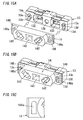
- FIGs. 19A and 19B show a photoelectric conversion connector which has been proposed conventionally.
- This connector comprises a plug 900 connected with an optical fiber cable, an MID substrate 920 detachably connected with this plug 900, and a metal shell 930 to which the plug 900 and MID substrate 920 are attached.
- the plug 900 has a plug body 901 formed of a rectangular synthetic resin mold.
- the left and right sides of the facing surface (the front face) with the MID substrate 920 in the plug 900 are formed with a pair of fit projections 902 projecting to the MID substrate 920 side.
- the front faces of the fit projections 902 are formed with openings of one side of a through hole 903 piercing the plug body 901 in the front and back direction, respectively.
- Two optical fiber cables 910 are inserted into the through holes 903 from the back side and then and fixed.
- the facing surface with the plug 900 in the MID substrate 920 is formed with a pair of fit cavities 921 into which the pair of fit projections 902 are fit, respectively.
- An optical element (a light emitting element or a light receiving element) 922 is mounted on the facing part with the end face of the optical fiber cable held by the plug 900 in the bottom of each fit cavity 921.
- the metal shell 930 comprises a rectangular bottom plate part 931, three hold spring parts 932 and three hold spring parts 933.
- the plug 900 and MID substrate 920 are put on the bottom plate part 931.
- the three hold spring parts 932 project from the front edge and the front side of left and right edges in the bottom plate part 931 toward upside, respectively and hold the MID substrate 920.
- the three hold spring parts 933 project from the back edge and the back side of left and right edges in the bottom plate part 931 toward upside, respectively and hold the plug body 901.
- the plug 900 When the plug 900 is connected to the MID substrate 920, the MID substrate 920 is inserted into the metal shell 930 from upside. Each hold spring part 932 is then latched to the MID substrate 920. Consequently, the MID substrate 920 is fixed to the metal shell 930, and a receptacle is obtained. The plug 900 is then inserted into the receptacle from upside. In the state that the fit projections 902 of the plug body 901 are fit into the fit cavities 921 of the MID substrate 920, each hold spring part 933 is latched to the plug body 901. Thereby, the plug 900 is connected to the receptacle, and the optical fiber cables 910 of the plug 900 face the optical elements 922 mounted on the MID substrate 920.
- the plug 900 is connected to the metal shell 930 fixing the MID substrate 920 form the vertical direction of the optical axes of the optical elements 922 mounted on the MID substrate 920. Because of this, there is an issue that positioning precision between the optical axes of the optical fiber cables 910 held by the plug 900 and the optical axes of the optical elements 922 is low, and also the position relationship of the optical axes changes when the optical fiber cables 910 held by the plug 900 receive stress, so that transmission loss increases. Also, the optical elements 922 are mounted on the facing surface with the plug 900 in the MID substrate 920, but there is another issue that influence of noise and so on increases in case that electrical separation between the optical elements is insufficient. In addition, as shown in FIG. 19B, in the state that the plug 900 is connected to the receptacle, the upside of attachment and detachment direction of the plug 900 in the connector is not shielded, and accordingly shield performance cannot be secured.
- Plug-socket connector apparatus for optical fiber termination of the present invention (hereinafter referred to as "first invention") comprises a plug, a socket and a photoelectric converter.
- the plug is fixed at one end of an optical fiber cable enclosing an optical fiber.
- the socket is configured to be mechanically connected with the plug.
- the socket also has a cavity of which bottom faces the end face of the optical fiber projected form the end of the optical fiber cable when mechanically connected with the plug.
- the photoelectric converter includes an optical element located on the bottom of the cavity, and is provided for the socket.
- the plug is a single ferrule plug and comprises a plug-base, a circular plug-tip and at least one latch.
- the plug-base has a hole into which the end of the optical fiber cable is inserted, and fixes the end inserted into the hole.
- the plug-tip has a pinhole into which the optical fiber projected from the end of the optical fiber cable is inserted.
- the at least one latch is formed on one part of the side face of the plug-tip.
- the socket further comprises terminals, a bore and a retainer.
- the terminals are located on the bottom face of the socket and are electrically connected with the converter.
- the terminals also are electrically connected with lands of a printed circuit board, respectively when the socket is mounted on the board.
- the bore is located at one side of the socket, and comes in contact with the remaining part of the side face of the plug-tip so that the plug can rotate around the pinhole when the plug is mechanically connected with the socket.
- the retainer retains said at least one latch so as to prevent the plug-tip from falling out of the bore and to restrict a rotation angle of the plug around the pinhole within a predetermined rotation angle range.
- the plug is a single ferrule plug, and accordingly, for example, upper and lower cases constituting a conventional plug can be omitted. Since the terminals are located on the bottom face of the socket and the bore is located at one side of the socket, it is possible to reduce dimension of a product equipped with the plug-socket connector apparatus of the invention in comparison with the plug-socket connector apparatus obtained from said hybrid optical-electrical connector apparatus. Moreover, since the plug can rotate within the predetermined rotation angle range around the pinhole, it is possible to absorb stress from the optical fiber cable while retaining the cable to prevent an optical axis of the optical fiber from deviating from the optical axis of the optical element.
- the plug rotates within the predetermined rotation angle range in response to stress from the cable, the plug rotates around the pinhole and therefore the optical axis of the optical fiber is constant. That is, since relative position relationship of the optical axis of the optical fiber cable with respect to the optical axis of the optical element does not change, precision of matching the optical axes can be improved in comparison with said photoelectric conversion connector.
- Plug-socket connector apparatus for optical fiber termination of the present invention (hereinafter referred to as "second invention") comprises first and second plugs, a socket and first and second photoelectric converters.
- the first and second plugs are fixed at one ends of first and second optical fiber cables enclosing first and second optical fibers, respectively.
- the socket is configured to be mechanically connected with the first and second plugs.
- the socket also has first and second cavities of which bottoms face the end faces of the first and second optical fibers projected form the ends of the first and second optical fiber cables, respectively when mechanically connected with the first and second plugs.
- the first and second photoelectric converters include first and second optical elements located on the bottoms of the first and second cavities, respectively, and are provided for the socket.
- the first plug is a single ferrule plug and comprises a first plug-base, a first circular plug-tip and at least one latch formed on one part of the side face of the first circular plug-tip.
- the first plug-base has a first hole into which the end of the first optical fiber cable is inserted, and fixes the end inserted into the first hole.
- the second circular plug-tip has a second pinhole into which the first optical fiber projected from the end of the first optical fiber cable is inserted.
- the second plug is a single ferrule plug and comprises a second plug-base, a second circular plug-tip and at least one latch formed on one part of the side face of the second circular plug-tip.
- the second plug-base has a second hole into which the end of the second optical fiber cable is inserted, and fixes the end inserted into the second hole.
- the second circular plug-tip has a second pinhole into which the first optical fiber projected from the end of the second optical fiber cable is inserted.
- the socket further comprises terminals, first and second bores and first and second retainers.
- the terminals are located on the bottom face of the socket and are electrically connected with the first and second photoelectric converters.
- the terminals are also electrically connected with lands of a printed circuit board, respectively when the socket is mounted on the board.
- the first and second bores are located at one side of the socket.
- the first and second bores come in contact with the remaining parts of the side faces of the first and second circular plug-tips so that the first and second plugs can rotate around the first and second pinholes, respectively when the first and second plugs are mechanically connected with the socket.
- the first and second retainers retain the latches of the first and second circular plug-tips so as to prevent the first and second circular plug-tips from falling out of the first and second bores and to restrict rotation angles of the first and second plugs around the first and second pinholes within predetermined first and second rotation angle ranges.
- the first invention further comprises a metal shell.
- the socket is formed of a molded interconnect device (MID) and a plug holder.
- the MID has the cavity, the photoelectric converter and the terminals.
- the holder has the bore and the retainer, and is fixed to the MID so that the bore is located in front of the cavity.
- the metal shell substantially covers the whole socket except at least a region of the terminals as well as the holder. In this embodiment, since the metal shell can substantially cover the whole MID except the region of the terminals, shield performance can be improved.
- the second invention further comprises a metal shell.
- the socket is formed of a molded interconnect device (MID) and a plug holder.
- the MID has the first and second cavities, the first and second photoelectric converters and the terminals.
- the plug holder has the first and second bores and the first and second retainers, and is fixed to the MID so that the first and second bores are located in front of the first and second cavities, respectively.
- the metal shell substantially covers the whole socket except at least a region of the terminals as well as the holder. In this embodiment, since the metal shell can substantially cover the whole MID except the region of the terminals, shield performance can be improved.
- the plug has first and second latches as the at least one latch.
- the first and second latches stick out from opposite sides of the side face of the plug-tip.
- the bore comprises a circular bore corresponding to the plug-tip and first and second cuts respectively corresponding to the first and second latches.
- the retainer is formed of first and second arched hollows, and first and second lock ribs.
- the first and second arched hollows are located in the back of the plug holder, and are formed around an axis of the circular bore continuously from the backs of the first and second cuts, respectively.
- the first lock rib is formed on the circumferential face of the first arched hollow between one part including the first cut of the first arched hollow and the remaining part of the first arched hollow.
- the second lock rib is formed on the circumferential face of the second arched hollow between one part including the second cut of the second arched hollow and the remaining part of the second arched hollow.
- Each of the remaining parts of the first and second arched hollows corresponds to the predetermined rotation angle range. In this embodiment, for example, even if the plug rotates within the rotation angle range in response to stress from the cable, the plug rotates around the pinhole and therefore the optical axis of the optical fiber is constant.
- the first plug has first and second latches as the at least one latch.
- the first and second latches stick out from opposite sides of the side face of the first circular plug-tip.
- the second plug has third and fourth latches as the at least one latch.
- the third and fourth latches stick out from opposite sides of the side face of the second circular plug-tip.
- the first bore comprises a first circular bore corresponding to the first circular plug-tip and first and second cuts respectively corresponding to the first and second latches.
- the second bore comprises a second circular bore corresponding to the second circular plug-tip and third and fourth cuts respectively corresponding to the third and fourth latches.
- the first retainer comprises first and second arched hollows, and first and second lock ribs.
- the first and second arched hollows are located in the back of the plug holder, and are formed around an axis of the first circular bore continuously from the backs of the first and second cuts, respectively.
- the first lock rib is formed on the circumferential face of the first arched hollow between one part including the first cut of the first arched hollow and the remaining part of the first arched hollow.
- the second lock rib is formed on the circumferential face of the second arched hollow between one part including the second cut of the second arched hollow and the remaining part of the second arched hollow.
- the second retainer comprises third and fourth arched hollows, and third and fourth lock ribs.
- the third and fourth arched hollows are located in the back of the plug holder, and are formed around an axis of the second circular bore continuously from the backs of the third and fourth cuts, respectively.
- the third lock rib is formed on the circumferential face of the third arched hollow between one part including the third cut of the third arched hollow and the remaining part of the third arched hollow.
- the fourth lock rib is formed on the circumferential face of the fourth arched hollow between one part including the fourth cut of the fourth arched hollow and the remaining part of the fourth arched hollow.
- Each of the remaining parts of the first and second arched hollows correspond to the first rotation angle range.
- Each of the remaining parts of the third and fourth arched hollows correspond to the second rotation angle range.
- the first and second plugs rotate within the first and second rotation angle ranges in response to stress from the cables, the first and second plug rotate around the first and second pinholes and therefore the optical axes of the first and second optical fibers are constant.
- the plug holder is made of conductive material, and the metal shell has at least one spring piece that elastically contacts the plug holder.
- the conductive holder is electrically connected with the metal shell, radiation noise caused by high speed transmission can be reduced and EMI can be improved.
- each of the first and second plugs is made of conductive material.
- the first and second bores are also shielded with the first and second plugs and accordingly shield effect can be further enhanced.
- one and the other of the first and second optical elements are a light emitting element and a light receiving element, respectively.
- the MID has a shield pattern that is located between the first and second cavities and is electrically connected with the metal shell.
- the metal shell has a base intervening between the MID and the printed circuit board.
- the base is provided with an earth tab that is located right under the shield pattern and is soldered to a ground pattern of the printed circuit board.
- the top of the MID is formed with an earth pattern electrically connected with the shield pattern.
- the metal shell further has at least one spring piece that elastically contacts the earth pattern. In this case, the shield effect of the shield pattern can be further enhanced.
- the plug holder further comprises first and second retaining holes outside the first and second bores, respectively.
- the MID further comprises first and second twin projections and first and second hollows.
- the first and second twin projections are respectively inserted into the first and second retaining holes to be retained.
- the first hollow is formed between the first twin projections
- the second hollow is formed between the second twin projections.
- the first and second hollows respectively form first and second gaps between the plug holder and the MID.
- the socket further comprises adhesive applied to each of the first and second hollows. In this embodiment, since quantity of the adhesive can be increased to enhance the adhesive strength, the MID and holder can be preferably fixed.
- the plug holder further comprises a through hole formed between the first and second bores.
- the MID further comprises a hollow that is larger than the through hole and forms a slit gap between the plug holder and the MID around the abyss of the through hole.
- the socket further comprises adhesive applied to the hollow. In this embodiment, since adhesive area can be spread to enhance adhesive strength, the MID and holder can be preferably fixed.
- the first and second arched hollows are formed around the axis of the first circular bore in opposite directions to each other continuously from the backs of the first and second cuts, respectively.
- a pair of the sockets are mirror-arranged so that a pair of the holders face to each other, rotation directions at both ends of each of the first and second optical fiber cables between the holders agree between the holders.
- the side faces of the first and second plug-bases are provided with first and second ribs for indicating rotation angles, respectively.
- the plug holder has first and second marks for representing rotation ranges of the first and second ribs, respectively.
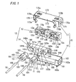
- FIG. 1 shows plug-socket connector apparatus for optical fiber termination, in accordance with an embodiment of the present invention.
- This apparatus comprises first and second plugs 10 and 11, a socket 12, and a metal shell 15.
- the first and second plugs 10 and 11 are fixed at one ends 180 and 190 of first and second optical fiber cables 18 and 19 enclosing first and second optical fibers 181 and 191, respectively.
- the plugs 10 and 11 are both single ferrule plugs and comprise first and second plug-bases 100 and 110 and first and second circular plug-tips 105 and 115, respectively.
- Each of the plugs 10 and 11 is also made of conductive material (e.g., conductive synthetic resin).
- the first and second plug-bases 100 and 110 have first and second holes 101 and 111 into which the ends 180 and 190 of the cables 18 and 19 are inserted, respectively, and fixes the ends 180 and 190 inserted into the holes 101 and 111, respectively.
- the ends 180 and 190 are respectively fixed to the holes 101 and 111 with adhesive.
- the side face of the plug-base 100 is provided with first ribs 102 and 103 for indicating the rotation angle of the plug 10
- the side face of the plug-base 110 is provided with second ribs 112 and 113 for indicating the rotation angle of the plug 11.
- the plug-tips 105 and 115 have first and second pinholes 106 and 116 into which the optical fibers 181 and 191 projected from the ends 180 and 190 of the cables 18 and 19 are inserted, respectively.
- the end face of the plug-tip 105 is formed with a hollow 105a larger than the pinhole 106.
- the end face of the plug-tip 115 is formed with a hollow (not shown) larger than the pinhole 116.
- the plug 10 also comprises first and second latches 107 and 108 sticking out from opposite sides in the side face of the plug-tip 105.
- the plug 11 comprises third and fourth latches 117 and 118 sticking out from opposite sides in the side face of the plug-tip 115.
- the positions of the ribs 102 and 103 correspond to those of the latches 107 and 108, respectively and the positions of the ribs 112 and 113 correspond to those of the latches 117 and 118, respectively.
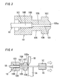
- FIG. 3 An example of fixing the plugs 10 and 11 to the cables 18 and 19 is explained with reference to FIG. 3.
- the optical fiber 181 projected from the end 180 of the cable 18 is adjusted to the length of the plug-tip 105 and then inserted from the hole 101 of the plug 10 to the pinhole 106. Afterwards, adhesive is injected into the pinhole 106 from the hole 101. At this time, surplus adhesive is shunted into the gap of the hollow 105a. Accordingly, it is possible to prevent the adhesive from attaching to the end face of the optical fiber 181 to fix the plug 10 to the cable 18. Similarly, the plug 11 is fixed to the cable 19.
- the optical fiber 181 projected from the end 180 of the cable 18 may be adjusted as shown in an example of FIG. 4. That is, the optical fiber 181 projected longer than the plug 10 is inserted from the hole 101 of the plug 10 to the pinhole 106. The optical fiber 181 projected from the plug-tip 105 is then cut along the end face of the plug-tip 105 with a backing block 1A and a diamond cutter 1B while being pulled through a pinch-jig 1C. At this point, the end face of the optical fiber 181 withdraws into the pinhole 106 of the plug-tip 105. Accordingly, fracture and dirt of the end face of the optical fiber 181 can be avoided. Similarly, the length of the optical fiber 191 of the cable 19 can be adjusted.
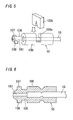
- the cables 18 and 19 can be also fixed as shown in examples of FIGs. 5 and 6.
- the plug-base 100 is formed with a cut 100a and the cable 18 in the cut 100a is fixed with a wedge 100b pressed into the cut 100a.
- the plug 10 is made of metal, and the cable 18 is fixed by tightening the circumference of the plug-base 100 of the plug 10.
- the socket 12 is configured to be mechanically connected with the plugs 10 and 11.
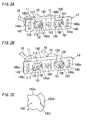
- the socket 12 is formed of an MID (molded interconnect device) 13 and a plug holder 14.
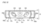
- the MID 13 has first and second cavities 130 and 131, first and second optical elements 132 and 133, first and second ICs (integrated circuits) 134 and 135, terminals 13 1 -13 9 , a shield pattern 13 10 , earth patterns 13 11 and 13 12 , a hollow 136, first twin projections 13a and 13b, second twin projections 13c and 13d, and first and second hollows 13e and 13f.
- the terminals and patterns are formed through processes of: forming a thin film of copper on the surface of a substrate of the MID 13; forming patterns with leaser beam; removing unnecessary parts thorough etching; and electroplating in order of, for example, nickel and gold.
- the first and second cavities 130 and 131 are located in the front side of the MID 13 that is in the shape of a quadratic prism.
- the bottoms 130a and 131a of the cavities 130 and 131 also faces the end faces of the fibers 181 and 191 projected from the ends 180 and 190 of the cables 18 and 19, respectively when the socket 12 is mechanically connected with the plugs 10 and 11.
- the first optical element 132 and the first IC 134 constitute a first photoelectric converter
- the second optical element 133 and the second IC 135 constitute a second photoelectric converter.
- the elements 132 and 133 are mounted on the bottoms 130a and 131a of the cavities 130 and 131, respectively. In this case, the elements 132 and 133 are located on the bottoms 130a and 131a so that the optical axes of the elements 132 and 133 agree with the optical axes of the optical fibers 181 and 191, respectively.
- One and the other of the elements 132 and 133 are also a light emitting element and a light receiving element, respectively.
- the elements 132 and 133 are the light receiving element (e.g., photodiode) and the light emitting element (e.g., light emitting diode), respectively.
- the element 132 has top and bottom electrodes, and the top electrode is electrically connected with the conductive pattern passing through a through hole 130b through a bonding wire.
- the bottom electrode is electrically connected with the conductive pattern passing through a through hole 130a.
- the element 133 also has top and bottom electrodes, and the top electrode of the element 133 is electrically connected with the conductive pattern passing through a through hole 131a through a bonding wire.
- the bottom electrode of the element 133 is electrically connected with the conductive pattern passing through a through hole 131b.
- the ICs 134 and 135 are mounted in two hollows of the rear side of the MID 13, respectively.
- the IC 134 is electrically connected with the element 132 through the conductive patterns passing through the through holes 130a and 130b, and performs signal processing of an input signal from the element 132.
- the IC 135 is electrically connected with the element 133 through the conductive patterns passing through the through holes 131a and 131b, and performs signal processing for producing an output signal to the element 133. Since the region where the IC 134 is mounted is located at the back side of the conductive pattern where the element 132 is mounted and the conductive pattern is a pattern corresponding to at least the size of the IC 134.
- the pattern is formed in at least a region piled up in front and back direction of mount region of the corresponding IC 134. Consequently, the whole region in which the pattern is formed can equally receive the weight when the IC 134 is mounted on the MID 13, and therefore mounting of the IC 134 can be performed certainly.
- the region where the IC 135 is mounted is located at the back side of the conductive pattern where the element 133 is mounted and the conductive pattern is a pattern corresponding to at least size of the IC 135. That is, the pattern is formed in at least a region piled up in front and back direction of mount region of the corresponding IC 135. Consequently, the whole region in which the pattern is formed can equally receive the weight when the IC 135 is mounted on the MID 13, and therefore mounting of the IC 135 can be performed certainly.
- the terminals 13 1 -13 9 are located on the bottom face of the MID 13 and are electrically connected with the first and second photoelectric converters, and are electrically connected with lands of a printed circuit board (not shown), respectively when the socket 12 is mounted on the board.
- the terminals 13 1 and 13 2 and the terminals 13 8 and 13 9 are located on the left and right base blocks of the bottom of the MID 13, respectively and the terminals 13 3 -13 7 are located on the center base block of the bottom. Height dimension of each of the base blocks is, for example, almost same as or slightly larger than the thickness dimension of the base of the metal shell 15.
- the terminals 13 1 -13 9 are also formed up to the slopes of the base blocks, and thereby back fillets can be formed and in consequence soldering strength can be enhanced.
- the IC 134 is electrically connected with the terminals 13 1 -13 4 .
- the IC 135 is electrically connected with the terminals 13 6 -13 9 .
- the shield pattern 13 10 is located on a partition wall between the cavities 130 and 131and is electrically connected with the metal shell 15 to shield between the cavities 130 and 131, namely the light receiving side and the light emitting side.
- the earth patterns 13 11 and 13 12 are formed over the front-end parts of the top and bottom of the MID 13, respectively and are electrically connected with the pattern 13 10 .
- the patterns 13 11 is also electrically connected with the terminal 13 5 through a conductive pattern formed on the back side of the MID 13.
- the hollow 136 is located between the cavities 130 and 131.
- the first twin projections 13a and 13b and second twin projections 13c and 13d are formed at the both ends of the front side of the MID 13, respectively.
- the first hollow 13e is located between the projections 13a and 13b, and the second hollow 13f is located between the projections 13c and 13d.
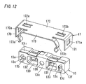
- the plug holder 14 has a body 140 formed with first and second bores 141 and 142, and a pair of flat face flanges 148 and 149 formed at the both ends of the body 140.
- This holder 14 is made of conductive material (e.g., conductive resin).
- the body 140 is provided with a through hole 143 (e.g., cavity and circular hole) and first and second retainers 144 and 145, and the flanges 148 and 149 are respectively formed with first and second retaining holes 148a and 149a.
- This holder 14 is fixed to the MID 13 so that the bores 141 and 142 are arranged in front of the cavities 130 and 131, respectively. That is, the first twin projections 13a and 13b and the second twin projections 13c and 13d are respectively inserted into the holes 148a and 149a to be retained. In this case, the holder 14 is positioned and held to the MID 13 so that the bores 141 and 142 are arranged in front of the cavities 130 and 131, respectively.
- the first and second hollows 13e and 13f respectively forms first and second gaps 13g and 13h between the holder 14 and the MID 13, namely at parts between the first twin projections 13a and 13b and the second twin projections 13c and 13d.
- the socket 12 further comprises the adhesive applied to each of the hollows 13e and 13f.
- the first and second bores 141 and 142 are located in the front side of the body 140.
- the bore 141 comprises a first circular bore 141a corresponding to the first circular plug-tip 105 and first and second cuts 141b and 141c respectively corresponding to the first and second latches 107 and 108.
- the bore 142 comprises a second circular bore 142a corresponding to the second circular plug-tip 115 and third and fourth cuts 142b and 142c respectively corresponding to the third and fourth latches 117 and 118.
- the through hole 143 is formed between the bores 141 and 142, and is located in front of the hollow 136 of the MID 13 when the MID 13 and holder 14 are fixed to each other.
- the hollow 136 is larger than the circular hole of the through hole 143 and accordingly forms a slit gap 136a between the holder 14 and the MID13 around the abyss of the through hole 143 (the circular hole).
- the MID 13 and holder 14 are preferably fixed through the adhesive.
- the MID 13 and holder 14 can be preferably fixed.
- the socket 12 further comprises the adhesive applied to the hollow 136.
- the first retainer 144 is configured to retain the latches 107 and 108 of the first circular plug-tip 105 when the plug-tip 105 is plugged in the first bore 141.
- the retainer 144 is configured to prevent the plug-tip 105 from falling out of the bore 141 and to restrict rotation angle of the plug 10 around the first pinhole 106 within a predetermined first rotation angle range R1 larger than each width dimension of the latches 107 and 108.
- the retainer 144 comprises first and second arched hollows 144a and 144b as well as first and second lock ribs 144c and 144d.
- the hollows 144a and 144b are located in the back of the holder 14, and are formed around an axis of the first circular bore 141a continuously from the backs of the first and second cuts 141b and 141c, respectively.
- the hollows 144a and 144b are formed in counterclockwise direction around the axis of the bore 141a continuously from the backs of the cuts 141b and 141c, respectively. Accordingly, the bore 141 comes in contact with the side face of the plug-tip 105 so that the plug 10 can rotate around the pinhole 106 when the plug 10 is mechanically connected with the socket 12.
- the first lock rib 144c is formed on the circumferential face of the hollow 144a between one part including the cut 141b of the hollow 144a and the remaining part of the hollow 144a.
- the second lock rib 144d is formed on the circumferential face of the hollow 144b between one part including the cut 141c of the hollow 144b and the remaining part of the hollow 144b. Therefore, when the latches 107 and 108 exist in the remaining parts of the hollows 144a and 144b, respectively, the rotation angle of the plug 10 is restricted within the range R1 corresponding to the remaining parts by the ribs 144c and 144d. In addition, the latches 107 and 108 are in contact with the bottoms of the hollows 144a and 144b, respectively, and thereby the plug-tip 105 is prevented from falling out of the bore 141.
- the second retainer 145 is configured to retain the latches 117 and 118 of the second circular plug-tip 115 when the plug-tip 115 is plugged in the second bore 142.
- the retainer 145 comprises third and fourth arched hollows 145a and 145b as well as third and fourth lock ribs 145c and 145d.
- the hollows 145a and 145b are located in the back of the holder 14, and are formed around an axis of the second circular bore 142a continuously from the backs of the third and fourth cuts 142b and 142c, respectively.
- the hollows 145a and 145b are formed in clockwise direction around the axis of the bore 142a continuously from the backs of the cuts 142b and 142c, respectively. Accordingly, the bore 142 comes in contact with the side face of the plug-tip 115 so that the plug 11 can rotate around the pinhole 116 when the plug 11 is mechanically connected with the socket 12.
- the third lock rib 145c is formed on the circumferential face of the hollow 145a between one part including the cut 142b of the hollow 145a and the remaining part of the hollow 145a.
- the fourth lock rib 145d is formed on the circumferential face of the hollow 145b between one part including the cut 142c of the hollow 145b and the remaining part of the hollow 145b. Therefore, when the latches 117 and 118 exist in the remaining parts of the hollows 145a and 145b, respectively, the rotation angle of the plug 11 is restricted within the range R2 corresponding to the remaining parts by the ribs 145c and 145d.
- the latches 117 and 118 are in contact with the bottoms of the hollows 145a and 145b, respectively, and thereby the plug-tip 115 is prevented from falling out of the bore 142.
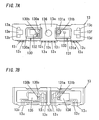
- the rotation directions of the plugs 10 and 11 are opposite directions to each other, it is possible to prevent, for example, twist of each of the cables 18 and 19 between a pair of the plug-socket connector apparatus.
- the sockets 12 and 12 are mirror-arranged so that the holders 14 and 14 face to each other, rotation directions at both ends of each of the cables 18 and 19 between the holders 14 and 14 agree between the holders.
- the hollows 144a and 144b are formed in clockwise direction around the axis of the bore 141a, and the hollows 145a and 145b are formed in counterclockwise direction around the axis of the bore 142a.
- the holder 14 is further provided with a first mark 146 for representing a rotation range of one of the first ribs 102 and 103 as well as a second mark 147 for representing a rotation range of one of the second ribs 112 and 113.
- Each of the marks 146 and 147 is formed of print, rib or the like. In this case, since a rotation angle of each of the plugs 10 and 11 is understood, the connection working efficiency is improved.
- the socket 12 is assembled by inserting the first twin projections 13a and 13b and the second twin projections 13c and 13d of the MID 13 into the first and second retaining holes 148a and 149a of the holder 14, respectively to apply adhesive to each of the hollow 136 and the first and second hollows 13e and 13f.
- the projections 13a and 13c and the projections 13b and 13d are in the shapes of U-and square-shapes, respectively and the retaining holes 148a and 149a are in the shapes corresponding to the projections 13a and 13b and the projections 13c and 13d, respectively, and therefore false insertion of the twin projections into the retaining holes is prevented.
- the metal shell 15 comprises a metal case 16 and a metal cover 17.
- the case 16 has front sides 160 and 161, left and right sides 162 and 163, a rear side 164, and a base 165.
- the front sides 160 and 161 cover the flanges 148 and 149 of the holder 14, respectively.
- the left and right sides 162 and 163 have lock nails 162a and 163a and covers the left and right sides of the socket 12, respectively.
- the rear side 164 covers the rear side of the socket 12.
- the base 165 has earth tabs 165a-165e, and covers one part of the bottom of the socket 12 to be in contact with the earth pattern 13 12 electrically connected with the shield pattern 13 10 and opens the terminals 13 1 -13 9 in the remaining part.
- the base 165 also intervenes between the MID 13 and a printed circuit board when the socket 12 is mounted on the board.
- the terminals 13 1 -13 9 are electrically connected with lands of the board, respectively and each of the tabs 165a-165e is soldered to a ground pattern of the board.
- the tab 165b is located right under the shield pattern 13 10 and is soldered to the ground pattern and accordingly shield effect of the pattern 13 10 can be enhanced. Consequently, electrical separation between optical elements 132 and 133 can be performed certainly.
- the cover 17 has left and right sides 170 and 171, a top 172 and an attachment 173.
- the left and right sides 170 and 171 have holes 170a and 171a locked and held at the lock nails 162a and 163a and cover the left and right sides 162 and 163, respectively. Accordingly, the cover 17 is electrically connected with the case 16.
- the top 172 has spring pieces 172a and 172b that elastically contacts the earth pattern 13 11 of the MID 13, and covers the top of the socket 12.
- the spring pieces 172a and 172b also press the earth pattern 13 12 of the MID 13 against the base 165 of the case 16. Accordingly, shield performance of the metal shell 15 can be further enhanced.
- the attachment 173 is joined to the front edge of the top 172 and has a pair of spring pieces 173a and 173b. These are formed to pinch the body 140 of the holder 14 between the pieces from the upper of the body 140. Therefore, the conductive holder 14 is electrically connected with the cover 17when the body 140 is pinched between the spring pieces 173a and 173b. As a result, radiation noise caused by high speed transmission can be reduced and EMI can be improved.
- the metal shell 15 incorporates with the socket 12 by putting the socket 12 in the case 16 and then covering the case 16 with the cover 17 to make the body 140 intervene between the spring pieces 173a and 173b of the attachment 173 and also to lock the lock nails 162a and 163a of the case 16 to the holes 170a and 171a of the cover 17, respectively.
- the plugs 10 and 11 are plugged in the bores 141 and 142, the bores 141 and 142 are also shielded with the plugs 10 and 11.
- a socket unit 1 in which the socket 12 is incorporated in the metal shell 15 is obtained.
- This unit 1 is mounted on a printed circuit board so that the terminal 13 1 -13 9 of the socket 12 are soldered onto lands of the board, respectively.
- the earth tabs 165a-165e are then soldered onto ground patterns of the board, respectively.
- the plug 10 is inserted into the bore 141 and rotated counterclockwise.
- the latches 107 and 108 of the plug 10 respectively pass over the lock ribs 144c and 144d to be locked within the range R1, and the plug 10 is retained by the retainer 144.
- the plug 11 is inserted into the bore 142 and rotated clockwise.
- the latches 117 and 118 of the plug 11 respectively pass over the lock ribs 145c and 145d to be locked within the range R2, and the plug 11 is retained by the retainer 145.
- the plugs 10 and 11 can be detached from the unit 1 by rotating the plugs 10 and 11 clockwise and counterclockwise, respectively.
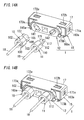
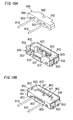
- the production method of the connector apparatus is explained with reference to FIGs. 15A-15C.
- the holder 14 In the state that the positions of the first twin projections 13a and 13b and second twin projections 13c and 13d of the MID 13 as well as the first retaining hole 148a and the second retaining hole 149a of the holder 14 are matched, the holder 14 is approached to the MID 13 and then the back surface of the holder 14 is contacted with the front surface of the MID 13 (see FIG. 15B).
- the first twin projections 13a and 13b and second twin projections 13c and 13d are respectively inserted into the first retaining hole 148a and the second retaining hole 149a to be fit, and thereby the MID 13 and the holder 14 are positioned relatively.
- the projections 13a and 13c and the projections 13b and 13d are in the shapes of U-and square-shapes, respectively and the retaining holes 148a and 149a are in the shapes corresponding to the projections 13a and 13b and the projections 13c and 13d, respectively, and therefore false insertion of the twin projections into the retaining holes is prevented.
- the hollow 13e between the twin projections 13a and 13b is deep in depth and is formed wider than the twin projections 13a and 13b.
- the hollow 13f between the twin projections 13c and 13d is deep in depth and is formed wider than the twin projections 13c and 13d. Accordingly, injection quantity of the adhesive is increased and thereby the adhesive strength can be heightened, and also there is an advantage that impletion of the adhesive becomes easy.
- the part corresponding to the circular hole of the through hole 143 of the holder 14 in the front of the MID 13 is also provided with the circular hollow 136 (a hole for injecting adhesive) larger in diameter (i.e., opening area) than the circular hole . Accordingly, adhesive filled into the cavity of the through hole 143 is filled into the hollow 136 through the circular hole.
- the circular hole of the through hole 143 is set to be smaller in diameter (i.e., opening area) than the hollow 136. Accordingly, a part of the adhesive filled into the cavity of the through hole 143 is attached to the circumferential part of the circular hole in the back of the holder 14 and thereby adhesion area of the adhesive can be increased to enhance adhesion strength between the MID 13 and holder 14.
- the socket 12 is put in the case 16 from upside.
- the case 16 is then covered with the cover 17 to make the body 140 intervene between the spring pieces 173a and 173b of the attachment 173 and also to lock the lock nails 162a and 163a of the case 16 to the holes 170a and 171a of the cover 17, respectively.
- the metal shell 15 incorporates with the socket 12.
- each of the plugs 10 and 11 is a single ferrule plug, and accordingly, for example, upper and lower cases constituting a conventional plug can be omitted. Since the terminals 13 1 -13 9 are located on the bottom face of the socket 12 (MID 13) and the bores 141 and 142 are located at the front side of the socket 12, it is possible to reduce thickness dimension of an electronic product equipped with the plug-socket connector apparatus of the invention in comparison with the plug-socket connector apparatus obtained from said hybrid optical-electrical connector apparatus.
- the plugs 10 and 11 can rotate within the ranges R1 and R2 around the pinholes 106 and 116, it is possible to absorb stress from the optical fiber cables 18 and 19 while retaining the cables 18 and 19 to prevent optical axes of the optical fibers 181 and 191 from deviating from optical axes of the optical elements 132 and 133. For example, even if the plug 10 rotates within the range R1 in response to stress from the cable 18, the plug 10 rotates around the pinhole 106 and therefore the optical axis of the optical fiber 181 is constant.
- each of the terminals 13 1 -13 9 is provided with a soldering ball 137.
- flatness can be improved and the terminals 13 1 -13 9 can be certainly soldered onto lands of a printed circuit board.
- each of the terminals 13 1 -13 9 is formed into a V-shape in section. In this case, since an area of each of the terminals 13 1 -13 9 is spread, soldering strength can be enhanced.
- each of the first and second plugs 10 and 11 and the plug holder 14 is made of insulating synthetic resin and is plated with conductive material. Also, in this case, it is possible to shield almost the whole socket 12 except the region of the terminals 13 1 -13 9 as well as the bores 141 and 142 respectively corresponding to the small plugs 10 and 11.
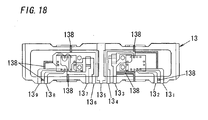
- surplus power supply patterns (138) of the conductive patterns in MID 13 are cut as shown in FIG. 18.
- the plug-socket connector apparatus for optical fiber termination comprises a plug and a socket.
- the plug is a single ferrule plug and comprises a plug-base, a circular plug-tip and at least one latch.
- the plug-base has a hole into which one end of an optical fiber cable is inserted, and fixes the end inserted into the hole.
- the circular plug-tip has a pinhole into which an optical fiber projected from the end of the optical fiber cable is inserted.
- the at least one latch is formed on one part of the side face of the plug-tip.
- the socket comprises a cavity, a photoelectric converter, terminals, a bore and a retainer.
- the bottom of the cavity faces the end face of the optical fiber projected form the end of the cable when the socket is mechanically connected with the plug.
- the converter includes an optical element located on the bottom of the cavity.
- the terminals are located on the bottom face of the socket and are electrically connected with the converter.
- the terminals are also electrically connected with lands of a printed circuit board, respectively when the socket is mounted on the board.
- the bore is located at one side of the socket, and comes in contact with the remaining part of the side face of the plug-tip so that the plug can rotate around the pinhole when the plug is mechanically connected with the socket.
- the retainer When the plug-tip is plugged in the bore, the retainer retains said at least one latch so as to prevent the plug-tip from falling out of the bore and to restrict a rotation angle of the plug around the pinhole within a predetermined rotation angle range.
- the plug can be configured in the same way as the first and second plugs 10 and 11.
- the socket can be configured by any one of a light receiving socket and a light emitting socket, obtained by dividing the MID 13 and the plug holder 14. In this case, the hollow 136, the through hole 143 and the shield pattern 13 10 are omitted, and also one of the terminals 13 1 -13 5 and the terminals 13 5 and 13 9 are omitted.
- the socket of this varied embodiment may be incorporated in a metal shell like the embodiment of FIG. 1.
Landscapes
- Physics & Mathematics (AREA)
- General Physics & Mathematics (AREA)
- Optics & Photonics (AREA)
- Optical Couplings Of Light Guides (AREA)
- Mechanical Coupling Of Light Guides (AREA)
Abstract
Description
- The invention relates generally to an optical fiber connector and more particularly to plug-socket connector apparatus for optical fiber termination.
-
Japanese Patent Application Publication Number H11-329637 -
Japanese Patent Application Publication Number H11-214100 - However, since the hybrid plug is connected to the hybrid socket in a vertical posture with respect to the print circuit board, thickness dimension of an electronic product equipped with the plug-socket connector apparatus becomes large. In addition, the hybrid plug is formed of the upper and lower cases, and accordingly the thickness dimension is further increased. Moreover, since the square shaped optical signal transmitter and optical signal receiver are plugged in two square shaped cavities of the hybrid socket, respectively, stress is put on the optical signal transmitter and optical signal receiver as well as the two cavities through the hybrid cord (optical fiber cables).
- FIGs. 19A and 19B show a photoelectric conversion connector which has been proposed conventionally. This connector comprises a
plug 900 connected with an optical fiber cable, anMID substrate 920 detachably connected with thisplug 900, and ametal shell 930 to which theplug 900 andMID substrate 920 are attached. Theplug 900 has aplug body 901 formed of a rectangular synthetic resin mold. The left and right sides of the facing surface (the front face) with theMID substrate 920 in theplug 900 are formed with a pair offit projections 902 projecting to theMID substrate 920 side. The front faces of thefit projections 902 are formed with openings of one side of athrough hole 903 piercing theplug body 901 in the front and back direction, respectively. Twooptical fiber cables 910 are inserted into the throughholes 903 from the back side and then and fixed. The facing surface with theplug 900 in theMID substrate 920 is formed with a pair offit cavities 921 into which the pair offit projections 902 are fit, respectively. An optical element (a light emitting element or a light receiving element) 922 is mounted on the facing part with the end face of the optical fiber cable held by theplug 900 in the bottom of eachfit cavity 921. Themetal shell 930 comprises a rectangularbottom plate part 931, threehold spring parts 932 and threehold spring parts 933. Theplug 900 andMID substrate 920 are put on thebottom plate part 931. The three holdspring parts 932 project from the front edge and the front side of left and right edges in thebottom plate part 931 toward upside, respectively and hold theMID substrate 920. The three holdspring parts 933 project from the back edge and the back side of left and right edges in thebottom plate part 931 toward upside, respectively and hold theplug body 901. - When the
plug 900 is connected to theMID substrate 920, theMID substrate 920 is inserted into themetal shell 930 from upside. Eachhold spring part 932 is then latched to theMID substrate 920. Consequently, theMID substrate 920 is fixed to themetal shell 930, and a receptacle is obtained. Theplug 900 is then inserted into the receptacle from upside. In the state that thefit projections 902 of theplug body 901 are fit into thefit cavities 921 of theMID substrate 920, eachhold spring part 933 is latched to theplug body 901. Thereby, theplug 900 is connected to the receptacle, and theoptical fiber cables 910 of theplug 900 face theoptical elements 922 mounted on theMID substrate 920. - In this photoelectric conversion connector, the
plug 900 is connected to themetal shell 930 fixing theMID substrate 920 form the vertical direction of the optical axes of theoptical elements 922 mounted on theMID substrate 920. Because of this, there is an issue that positioning precision between the optical axes of theoptical fiber cables 910 held by theplug 900 and the optical axes of theoptical elements 922 is low, and also the position relationship of the optical axes changes when theoptical fiber cables 910 held by theplug 900 receive stress, so that transmission loss increases. Also, theoptical elements 922 are mounted on the facing surface with theplug 900 in theMID substrate 920, but there is another issue that influence of noise and so on increases in case that electrical separation between the optical elements is insufficient. In addition, as shown in FIG. 19B, in the state that theplug 900 is connected to the receptacle, the upside of attachment and detachment direction of theplug 900 in the connector is not shielded, and accordingly shield performance cannot be secured. - It is an object of the present invention to avoid increasing dimension of a product equipped with plug-socket connector apparatus of the invention and to absorb stress from an optical fiber cable while retaining the cable to prevent an optical axis of the optical fiber from deviating from an optical axis of an optical element.
- Plug-socket connector apparatus for optical fiber termination of the present invention (hereinafter referred to as "first invention") comprises a plug, a socket and a photoelectric converter. The plug is fixed at one end of an optical fiber cable enclosing an optical fiber. The socket is configured to be mechanically connected with the plug. The socket also has a cavity of which bottom faces the end face of the optical fiber projected form the end of the optical fiber cable when mechanically connected with the plug. The photoelectric converter includes an optical element located on the bottom of the cavity, and is provided for the socket. The plug is a single ferrule plug and comprises a plug-base, a circular plug-tip and at least one latch. The plug-base has a hole into which the end of the optical fiber cable is inserted, and fixes the end inserted into the hole. The plug-tip has a pinhole into which the optical fiber projected from the end of the optical fiber cable is inserted. The at least one latch is formed on one part of the side face of the plug-tip. The socket further comprises terminals, a bore and a retainer. The terminals are located on the bottom face of the socket and are electrically connected with the converter. The terminals also are electrically connected with lands of a printed circuit board, respectively when the socket is mounted on the board. The bore is located at one side of the socket, and comes in contact with the remaining part of the side face of the plug-tip so that the plug can rotate around the pinhole when the plug is mechanically connected with the socket. When the plug-tip is plugged in the bore, the retainer retains said at least one latch so as to prevent the plug-tip from falling out of the bore and to restrict a rotation angle of the plug around the pinhole within a predetermined rotation angle range.
- In this invention, the plug is a single ferrule plug, and accordingly, for example, upper and lower cases constituting a conventional plug can be omitted. Since the terminals are located on the bottom face of the socket and the bore is located at one side of the socket, it is possible to reduce dimension of a product equipped with the plug-socket connector apparatus of the invention in comparison with the plug-socket connector apparatus obtained from said hybrid optical-electrical connector apparatus. Moreover, since the plug can rotate within the predetermined rotation angle range around the pinhole, it is possible to absorb stress from the optical fiber cable while retaining the cable to prevent an optical axis of the optical fiber from deviating from the optical axis of the optical element. In addition, even if the plug rotates within the predetermined rotation angle range in response to stress from the cable, the plug rotates around the pinhole and therefore the optical axis of the optical fiber is constant. That is, since relative position relationship of the optical axis of the optical fiber cable with respect to the optical axis of the optical element does not change, precision of matching the optical axes can be improved in comparison with said photoelectric conversion connector.
- Plug-socket connector apparatus for optical fiber termination of the present invention (hereinafter referred to as "second invention") comprises first and second plugs, a socket and first and second photoelectric converters. The first and second plugs are fixed at one ends of first and second optical fiber cables enclosing first and second optical fibers, respectively. The socket is configured to be mechanically connected with the first and second plugs. The socket also has first and second cavities of which bottoms face the end faces of the first and second optical fibers projected form the ends of the first and second optical fiber cables, respectively when mechanically connected with the first and second plugs. The first and second photoelectric converters include first and second optical elements located on the bottoms of the first and second cavities, respectively, and are provided for the socket. The first plug is a single ferrule plug and comprises a first plug-base, a first circular plug-tip and at least one latch formed on one part of the side face of the first circular plug-tip. The first plug-base has a first hole into which the end of the first optical fiber cable is inserted, and fixes the end inserted into the first hole. The second circular plug-tip has a second pinhole into which the first optical fiber projected from the end of the first optical fiber cable is inserted. The second plug is a single ferrule plug and comprises a second plug-base, a second circular plug-tip and at least one latch formed on one part of the side face of the second circular plug-tip. The second plug-base has a second hole into which the end of the second optical fiber cable is inserted, and fixes the end inserted into the second hole. The second circular plug-tip has a second pinhole into which the first optical fiber projected from the end of the second optical fiber cable is inserted. The socket further comprises terminals, first and second bores and first and second retainers. The terminals are located on the bottom face of the socket and are electrically connected with the first and second photoelectric converters. The terminals are also electrically connected with lands of a printed circuit board, respectively when the socket is mounted on the board. The first and second bores are located at one side of the socket. The first and second bores come in contact with the remaining parts of the side faces of the first and second circular plug-tips so that the first and second plugs can rotate around the first and second pinholes, respectively when the first and second plugs are mechanically connected with the socket. When the first and second circular plug-tips are plugged in the first and second bores, respectively, the first and second retainers retain the latches of the first and second circular plug-tips so as to prevent the first and second circular plug-tips from falling out of the first and second bores and to restrict rotation angles of the first and second plugs around the first and second pinholes within predetermined first and second rotation angle ranges. In this invention, it is possible to avoid increasing dimension of a product equipped with the plug-socket connector apparatus of the invention and to absorb stress from the optical fiber cables while retaining the cables to prevent optical axes of the optical fibers from deviating from the optical axes of the optical elements.
- In an embodiment of the first invention, it further comprises a metal shell. The socket is formed of a molded interconnect device (MID) and a plug holder. The MID has the cavity, the photoelectric converter and the terminals. The holder has the bore and the retainer, and is fixed to the MID so that the bore is located in front of the cavity. The metal shell substantially covers the whole socket except at least a region of the terminals as well as the holder. In this embodiment, since the metal shell can substantially cover the whole MID except the region of the terminals, shield performance can be improved.
- In an embodiment of the second invention, it further comprises a metal shell. The socket is formed of a molded interconnect device (MID) and a plug holder. The MID has the first and second cavities, the first and second photoelectric converters and the terminals. The plug holder has the first and second bores and the first and second retainers, and is fixed to the MID so that the first and second bores are located in front of the first and second cavities, respectively. The metal shell substantially covers the whole socket except at least a region of the terminals as well as the holder. In this embodiment, since the metal shell can substantially cover the whole MID except the region of the terminals, shield performance can be improved.
- In an embodiment of the first invention, the plug has first and second latches as the at least one latch. The first and second latches stick out from opposite sides of the side face of the plug-tip. The bore comprises a circular bore corresponding to the plug-tip and first and second cuts respectively corresponding to the first and second latches. The retainer is formed of first and second arched hollows, and first and second lock ribs. The first and second arched hollows are located in the back of the plug holder, and are formed around an axis of the circular bore continuously from the backs of the first and second cuts, respectively. The first lock rib is formed on the circumferential face of the first arched hollow between one part including the first cut of the first arched hollow and the remaining part of the first arched hollow. The second lock rib is formed on the circumferential face of the second arched hollow between one part including the second cut of the second arched hollow and the remaining part of the second arched hollow. Each of the remaining parts of the first and second arched hollows corresponds to the predetermined rotation angle range. In this embodiment, for example, even if the plug rotates within the rotation angle range in response to stress from the cable, the plug rotates around the pinhole and therefore the optical axis of the optical fiber is constant.
- In an embodiment of the second invention, the first plug has first and second latches as the at least one latch. The first and second latches stick out from opposite sides of the side face of the first circular plug-tip. The second plug has third and fourth latches as the at least one latch. The third and fourth latches stick out from opposite sides of the side face of the second circular plug-tip. The first bore comprises a first circular bore corresponding to the first circular plug-tip and first and second cuts respectively corresponding to the first and second latches. The second bore comprises a second circular bore corresponding to the second circular plug-tip and third and fourth cuts respectively corresponding to the third and fourth latches. The first retainer comprises first and second arched hollows, and first and second lock ribs. The first and second arched hollows are located in the back of the plug holder, and are formed around an axis of the first circular bore continuously from the backs of the first and second cuts, respectively. The first lock rib is formed on the circumferential face of the first arched hollow between one part including the first cut of the first arched hollow and the remaining part of the first arched hollow. The second lock rib is formed on the circumferential face of the second arched hollow between one part including the second cut of the second arched hollow and the remaining part of the second arched hollow. The second retainer comprises third and fourth arched hollows, and third and fourth lock ribs. The third and fourth arched hollows are located in the back of the plug holder, and are formed around an axis of the second circular bore continuously from the backs of the third and fourth cuts, respectively. The third lock rib is formed on the circumferential face of the third arched hollow between one part including the third cut of the third arched hollow and the remaining part of the third arched hollow. The fourth lock rib is formed on the circumferential face of the fourth arched hollow between one part including the fourth cut of the fourth arched hollow and the remaining part of the fourth arched hollow. Each of the remaining parts of the first and second arched hollows correspond to the first rotation angle range. Each of the remaining parts of the third and fourth arched hollows correspond to the second rotation angle range. In this embodiment, for example, even if the first and second plugs rotate within the first and second rotation angle ranges in response to stress from the cables, the first and second plug rotate around the first and second pinholes and therefore the optical axes of the first and second optical fibers are constant.
- In an embodiment of the second invention, the plug holder is made of conductive material, and the metal shell has at least one spring piece that elastically contacts the plug holder. In this case, since the conductive holder is electrically connected with the metal shell, radiation noise caused by high speed transmission can be reduced and EMI can be improved. Moreover, it is possible to shield almost the whole socket except the region of the terminals as well as the first and second bores respectively corresponding to the first and second plugs.
- In an embodiment of the second invention, each of the first and second plugs is made of conductive material. In this case, when the first and second plugs are plugged in the first and second bores, the first and second bores are also shielded with the first and second plugs and accordingly shield effect can be further enhanced.
- In an example of the second invention, one and the other of the first and second optical elements are a light emitting element and a light receiving element, respectively. The MID has a shield pattern that is located between the first and second cavities and is electrically connected with the metal shell. The metal shell has a base intervening between the MID and the printed circuit board. The base is provided with an earth tab that is located right under the shield pattern and is soldered to a ground pattern of the printed circuit board. In this embodiment, since shield effect of the shield pattern can be enhanced, electrical separation between the light emitting element and the light receiving element can be performed certainly.
- In an embodiment of the second invention, the top of the MID is formed with an earth pattern electrically connected with the shield pattern. The metal shell further has at least one spring piece that elastically contacts the earth pattern. In this case, the shield effect of the shield pattern can be further enhanced.
- In an embodiment of the second invention, the plug holder further comprises first and second retaining holes outside the first and second bores, respectively. The MID further comprises first and second twin projections and first and second hollows. The first and second twin projections are respectively inserted into the first and second retaining holes to be retained. The first hollow is formed between the first twin projections, and the second hollow is formed between the second twin projections. The first and second hollows respectively form first and second gaps between the plug holder and the MID. The socket further comprises adhesive applied to each of the first and second hollows. In this embodiment, since quantity of the adhesive can be increased to enhance the adhesive strength, the MID and holder can be preferably fixed.
- In an embodiment of the second invention, the plug holder further comprises a through hole formed between the first and second bores. The MID further comprises a hollow that is larger than the through hole and forms a slit gap between the plug holder and the MID around the abyss of the through hole. The socket further comprises adhesive applied to the hollow. In this embodiment, since adhesive area can be spread to enhance adhesive strength, the MID and holder can be preferably fixed.
- In an embodiment of the second invention, the first and second arched hollows are formed around the axis of the first circular bore in opposite directions to each other continuously from the backs of the first and second cuts, respectively. In this case, for example, it is possible to prevent twist of each of the first and second optical fiber cables between a pair of the plug-socket connector apparatus. For example, when a pair of the sockets are mirror-arranged so that a pair of the holders face to each other, rotation directions at both ends of each of the first and second optical fiber cables between the holders agree between the holders.
- In an embodiment of the second invention, the side faces of the first and second plug-bases are provided with first and second ribs for indicating rotation angles, respectively. The plug holder has first and second marks for representing rotation ranges of the first and second ribs, respectively. In this embodiment, since a rotation angle of each of the first and second plugs is understood, the connection working efficiency is improved.
- Preferred embodiments of the invention will now be described in further details. Other features and advantages of the present invention will become better understood with regard to the following detailed description and accompanying drawings where:
- FIG. 1 is an exploded perspective view of plug-socket connector apparatus for optical fiber termination, in accordance with an embodiment of the present invention;
- FIGs. 2A is a perspective view of a plug holder when first and second plugs are inserted into first and second bores of the holder;
- FIGs. 2B is a perspective view of the holder when the first and second plugs are locked;
- FIGs. 2C is an enlarged view of part of the holder;
- FIG. 3 is a sectional view of the first plug fixed at one end of a first optical fiber cable;
- FIG. 4 is an explanatory diagram of length adjustment of a first optical fiber projected from the cable;
- FIG. 5 illustrates an example of fix of the plug to the cable;
- FIG. 6 illustrates an example of fix of the plug to the cable;
- FIGs. 7A and 7B are front and back views of a socket of the plug-socket connector apparatus, respectively;
- FIGs. 8A and 8B are bottom and right side views of an MID (molded interconnect device) of the socket, respectively;
- FIGs. 9A and 9B are front and back views of the holder combined with the first and second plugs, respectively;
- FIG. 10A is an enlarged sectional view of part of the socket;
- FIG. 10B is a sectional view along line A-A of FIG. 10A;
- FIGs. 11 is a perspective view of a metal case of the plug-socket connector apparatus and the MID;
- FIGs. 12 is a perspective view of a metal cover of the plug-socket connector apparatus and the MID;
- FIG. 13 is a front view of a socket unit of the plug-socket connector apparatus;
- FIGs. 14A and 14B are explanatory diagrams of connection of the first and second plugs to the socket unit;
- FIGs. 15A-15C is an explanatory diagram of production method of the connector apparatus;
- FIG. 16 illustrates a modified embodiment;
- FIG. 17 illustrates a modified embodiment;
- FIG. 18 illustrates a modified embodiment; and
- FIGs. 19A and 19B illustrate a photoelectric conversion connector which has been proposed conventionally.
- FIG. 1 shows plug-socket connector apparatus for optical fiber termination, in accordance with an embodiment of the present invention. This apparatus comprises first and
second plugs socket 12, and ametal shell 15. - The first and
second plugs optical fiber cables optical fibers plugs bases tips plugs - The first and second plug-
bases second holes cables ends holes ends holes base 100 is provided withfirst ribs plug 10, and the side face of the plug-base 110 is provided withsecond ribs plug 11. - As shown in FIGs. 1, 2A, 2B and 3, the plug-
tips second pinholes optical fibers ends cables tip 105 is formed with a hollow 105a larger than thepinhole 106. Similarly, the end face of the plug-tip 115 is formed with a hollow (not shown) larger than thepinhole 116. Theplug 10 also comprises first andsecond latches tip 105. Similarly, theplug 11 comprises third andfourth latches tip 115. The positions of theribs latches ribs latches - An example of fixing the
plugs cables optical fiber 181 projected from theend 180 of thecable 18 is adjusted to the length of the plug-tip 105 and then inserted from thehole 101 of theplug 10 to thepinhole 106. Afterwards, adhesive is injected into thepinhole 106 from thehole 101. At this time, surplus adhesive is shunted into the gap of the hollow 105a. Accordingly, it is possible to prevent the adhesive from attaching to the end face of theoptical fiber 181 to fix theplug 10 to thecable 18. Similarly, theplug 11 is fixed to thecable 19. - However, not limited to this, the
optical fiber 181 projected from theend 180 of thecable 18 may be adjusted as shown in an example of FIG. 4. That is, theoptical fiber 181 projected longer than theplug 10 is inserted from thehole 101 of theplug 10 to thepinhole 106. Theoptical fiber 181 projected from the plug-tip 105 is then cut along the end face of the plug-tip 105 with abacking block 1A and adiamond cutter 1B while being pulled through a pinch-jig 1C. At this point, the end face of theoptical fiber 181 withdraws into thepinhole 106 of the plug-tip 105. Accordingly, fracture and dirt of the end face of theoptical fiber 181 can be avoided. Similarly, the length of theoptical fiber 191 of thecable 19 can be adjusted. In this case, though adhesive may be injected into thepinholes holes optical fibers cables base 100 is formed with acut 100a and thecable 18 in thecut 100a is fixed with awedge 100b pressed into thecut 100a. In the example of FIG. 6, theplug 10 is made of metal, and thecable 18 is fixed by tightening the circumference of the plug-base 100 of theplug 10. - The
socket 12 is configured to be mechanically connected with theplugs socket 12 is formed of an MID (molded interconnect device) 13 and aplug holder 14. - As shown in FIGs. 1, 7A, 7B, 8A and 8B, the
MID 13 has first andsecond cavities optical elements shield pattern 1310,earth patterns first twin projections second twin projections second hollows MID 13; forming patterns with leaser beam; removing unnecessary parts thorough etching; and electroplating in order of, for example, nickel and gold. - The first and
second cavities MID 13 that is in the shape of a quadratic prism. Thebottoms cavities fibers ends cables socket 12 is mechanically connected with theplugs - The first
optical element 132 and thefirst IC 134 constitute a first photoelectric converter, and the secondoptical element 133 and thesecond IC 135 constitute a second photoelectric converter. Theelements bottoms cavities elements bottoms elements optical fibers elements elements element 132 has top and bottom electrodes, and the top electrode is electrically connected with the conductive pattern passing through a throughhole 130b through a bonding wire. The bottom electrode is electrically connected with the conductive pattern passing through a throughhole 130a. Theelement 133 also has top and bottom electrodes, and the top electrode of theelement 133 is electrically connected with the conductive pattern passing through a throughhole 131a through a bonding wire. The bottom electrode of theelement 133 is electrically connected with the conductive pattern passing through a throughhole 131b. - On the other hands, the
ICs MID 13, respectively. TheIC 134 is electrically connected with theelement 132 through the conductive patterns passing through the throughholes element 132. TheIC 135 is electrically connected with theelement 133 through the conductive patterns passing through the throughholes element 133. Since the region where theIC 134 is mounted is located at the back side of the conductive pattern where theelement 132 is mounted and the conductive pattern is a pattern corresponding to at least the size of theIC 134. In other words, the pattern is formed in at least a region piled up in front and back direction of mount region of thecorresponding IC 134. Consequently, the whole region in which the pattern is formed can equally receive the weight when theIC 134 is mounted on theMID 13, and therefore mounting of theIC 134 can be performed certainly. Similarly, since the region where theIC 135 is mounted is located at the back side of the conductive pattern where theelement 133 is mounted and the conductive pattern is a pattern corresponding to at least size of theIC 135. That is, the pattern is formed in at least a region piled up in front and back direction of mount region of thecorresponding IC 135. Consequently, the whole region in which the pattern is formed can equally receive the weight when theIC 135 is mounted on theMID 13, and therefore mounting of theIC 135 can be performed certainly. - The terminals 131-139 are located on the bottom face of the
MID 13 and are electrically connected with the first and second photoelectric converters, and are electrically connected with lands of a printed circuit board (not shown), respectively when thesocket 12 is mounted on the board. Theterminals terminals MID 13, respectively and the terminals 133-137 are located on the center base block of the bottom. Height dimension of each of the base blocks is, for example, almost same as or slightly larger than the thickness dimension of the base of themetal shell 15. The terminals 131-139 are also formed up to the slopes of the base blocks, and thereby back fillets can be formed and in consequence soldering strength can be enhanced. TheIC 134 is electrically connected with the terminals 131-134. TheIC 135 is electrically connected with the terminals 136-139. - The
shield pattern 1310 is located on a partition wall between thecavities 130 and 131and is electrically connected with themetal shell 15 to shield between thecavities earth patterns MID 13, respectively and are electrically connected with thepattern 1310. Thepatterns 1311 is also electrically connected with the terminal 135 through a conductive pattern formed on the back side of theMID 13. The hollow 136 is located between thecavities first twin projections twin projections MID 13, respectively. The first hollow 13e is located between theprojections projections - As shown in FIGs. 1, 2A, 2B, 2C and 9B, the
plug holder 14 has abody 140 formed with first andsecond bores flat face flanges body 140. Thisholder 14 is made of conductive material (e.g., conductive resin). In addition, thebody 140 is provided with a through hole 143 (e.g., cavity and circular hole) and first andsecond retainers flanges holes - This
holder 14 is fixed to theMID 13 so that thebores cavities first twin projections second twin projections holes holder 14 is positioned and held to theMID 13 so that thebores cavities second hollows second gaps holder 14 and theMID 13, namely at parts between thefirst twin projections second twin projections holder 14 is in contact with the front face of theMID 13, adhesive (not shown) is applied to each of thehollows gaps MID 13 andholder 14 are fixed to each other through the adhesive. In such construction, since the adhesive strength can be increased by spreading area to which the adhesive is applied to increase quantity of the adhesive, theMID 13 andholder 14 can be preferably fixed. In short, thesocket 12 further comprises the adhesive applied to each of thehollows - The first and
second bores body 140. Thebore 141 comprises a firstcircular bore 141a corresponding to the first circular plug-tip 105 and first andsecond cuts second latches bore 142 comprises a secondcircular bore 142a corresponding to the second circular plug-tip 115 and third andfourth cuts fourth latches - The through
hole 143 is formed between thebores MID 13 when theMID 13 andholder 14 are fixed to each other. In addition, as shown in FIGs. 10A and 10B, the hollow 136 is larger than the circular hole of the throughhole 143 and accordingly forms aslit gap 136a between theholder 14 and the MID13 around the abyss of the through hole 143 (the circular hole). When the back face of theholder 14 is in contact with the front face of theMID 13, adhesive is applied to not only each of thehollows gaps gap 136a). Afterwards, if the adhesive applied to the hollow 136 hardens, theMID 13 andholder 14 are preferably fixed through the adhesive. In this construction, since adhesive area can be spread to enhance adhesive strength, theMID 13 andholder 14 can be preferably fixed. In short, thesocket 12 further comprises the adhesive applied to the hollow 136. - As shown in FIG. 9B, the
first retainer 144 is configured to retain thelatches tip 105 when the plug-tip 105 is plugged in thefirst bore 141. In addition, theretainer 144 is configured to prevent the plug-tip 105 from falling out of thebore 141 and to restrict rotation angle of theplug 10 around thefirst pinhole 106 within a predetermined first rotation angle range R1 larger than each width dimension of thelatches retainer 144 comprises first and secondarched hollows second lock ribs hollows holder 14, and are formed around an axis of the firstcircular bore 141a continuously from the backs of the first andsecond cuts hollows bore 141a continuously from the backs of thecuts bore 141 comes in contact with the side face of the plug-tip 105 so that theplug 10 can rotate around thepinhole 106 when theplug 10 is mechanically connected with thesocket 12. Thefirst lock rib 144c is formed on the circumferential face of the hollow 144a between one part including thecut 141b of the hollow 144a and the remaining part of the hollow 144a. Thesecond lock rib 144d is formed on the circumferential face of the hollow 144b between one part including thecut 141c of the hollow 144b and the remaining part of the hollow 144b. Therefore, when thelatches hollows plug 10 is restricted within the range R1 corresponding to the remaining parts by theribs latches hollows tip 105 is prevented from falling out of thebore 141. - Similarly, the
second retainer 145 is configured to retain thelatches tip 115 when the plug-tip 115 is plugged in thesecond bore 142. In addition, theretainer 145 is configured to prevent the plug-tip 115 from falling out of thebore 142 and to restrict rotation angle of theplug 11 around thesecond pinhole 116 within a predetermined second rotation angle range R2 (e.g., R2=R1) larger than each width dimension of thelatches retainer 145 comprises third and fourtharched hollows fourth lock ribs hollows holder 14, and are formed around an axis of the secondcircular bore 142a continuously from the backs of the third andfourth cuts hollows bore 142a continuously from the backs of thecuts bore 142 comes in contact with the side face of the plug-tip 115 so that theplug 11 can rotate around thepinhole 116 when theplug 11 is mechanically connected with thesocket 12. Thethird lock rib 145c is formed on the circumferential face of the hollow 145a between one part including thecut 142b of the hollow 145a and the remaining part of the hollow 145a. Thefourth lock rib 145d is formed on the circumferential face of the hollow 145b between one part including thecut 142c of the hollow 145b and the remaining part of the hollow 145b. Therefore, when thelatches hollows plug 11 is restricted within the range R2 corresponding to the remaining parts by theribs latches hollows tip 115 is prevented from falling out of thebore 142. Thus, in case that the rotation directions of theplugs cables sockets holders cables holders hollows bore 141a, and thehollows bore 142a. - As shown in FIG. 9A, the
holder 14 is further provided with afirst mark 146 for representing a rotation range of one of thefirst ribs second mark 147 for representing a rotation range of one of thesecond ribs marks plugs - The
socket 12 is assembled by inserting thefirst twin projections second twin projections MID 13 into the first and second retainingholes holder 14, respectively to apply adhesive to each of the hollow 136 and the first andsecond hollows projections projections holes projections projections - As shown in FIGs. 1, 11, 12 and 13, the
metal shell 15 comprises ametal case 16 and ametal cover 17. Thecase 16 hasfront sides right sides rear side 164, and abase 165. Thefront sides flanges holder 14, respectively. The left andright sides lock nails socket 12, respectively. Therear side 164 covers the rear side of thesocket 12. Thebase 165 hasearth tabs 165a-165e, and covers one part of the bottom of thesocket 12 to be in contact with theearth pattern 1312 electrically connected with theshield pattern 1310 and opens the terminals 131-139 in the remaining part. The base 165 also intervenes between theMID 13 and a printed circuit board when thesocket 12 is mounted on the board. In this point, the terminals 131-139 are electrically connected with lands of the board, respectively and each of thetabs 165a-165e is soldered to a ground pattern of the board. Especially, thetab 165b is located right under theshield pattern 1310 and is soldered to the ground pattern and accordingly shield effect of thepattern 1310 can be enhanced. Consequently, electrical separation betweenoptical elements - The
cover 17 has left andright sides attachment 173. The left andright sides holes right sides cover 17 is electrically connected with thecase 16. The top 172 hasspring pieces earth pattern 1311 of theMID 13, and covers the top of thesocket 12. Thespring pieces earth pattern 1312 of theMID 13 against thebase 165 of thecase 16. Accordingly, shield performance of themetal shell 15 can be further enhanced. Theattachment 173 is joined to the front edge of the top 172 and has a pair ofspring pieces body 140 of theholder 14 between the pieces from the upper of thebody 140. Therefore, theconductive holder 14 is electrically connected with the cover 17when thebody 140 is pinched between thespring pieces - The
metal shell 15 incorporates with thesocket 12 by putting thesocket 12 in thecase 16 and then covering thecase 16 with thecover 17 to make thebody 140 intervene between thespring pieces attachment 173 and also to lock the lock nails 162a and 163a of thecase 16 to theholes cover 17, respectively. In this case, it is possible to shield almost thewhole socket 12 except the region of the terminals 131-139 as well as thebores small plugs plugs bores bores plugs - That is, as shown in FIGs. 14A and 14B, a
socket unit 1 in which thesocket 12 is incorporated in themetal shell 15 is obtained. Thisunit 1 is mounted on a printed circuit board so that the terminal 131-139 of thesocket 12 are soldered onto lands of the board, respectively. Theearth tabs 165a-165e are then soldered onto ground patterns of the board, respectively. Afterwards, theplug 10 is inserted into thebore 141 and rotated counterclockwise. At this point, thelatches plug 10 respectively pass over thelock ribs plug 10 is retained by theretainer 144. On the other hands, theplug 11 is inserted into thebore 142 and rotated clockwise. At this point, thelatches plug 11 respectively pass over thelock ribs plug 11 is retained by theretainer 145. By the way, theplugs unit 1 by rotating theplugs - The production method of the connector apparatus is explained with reference to FIGs. 15A-15C. In the state that the positions of the
first twin projections twin projections MID 13 as well as thefirst retaining hole 148a and thesecond retaining hole 149a of theholder 14 are matched, theholder 14 is approached to theMID 13 and then the back surface of theholder 14 is contacted with the front surface of the MID 13 (see FIG. 15B). At this point, thefirst twin projections twin projections first retaining hole 148a and thesecond retaining hole 149a to be fit, and thereby theMID 13 and theholder 14 are positioned relatively. In addition, theprojections projections holes projections projections - And in the state that the back surface of the
holder 14 is contacted with the front surface of theMID 13, adhesive is filled into the hollow 13e between thetwin projections twin projections hole 143, and then hardened. Thereby, theMID 13 andholder 14 are coupled through the adhesive. Herein, a fit projection inserted into the retaininghole 148a of theflange 148 is divided into thetwin projections hole 149a of theflange 149 is divided into thetwin projections twin projections twin projections twin projections twin projections hole 143 of theholder 14 in the front of theMID 13 is also provided with the circular hollow 136 (a hole for injecting adhesive) larger in diameter (i.e., opening area) than the circular hole . Accordingly, adhesive filled into the cavity of the throughhole 143 is filled into the hollow 136 through the circular hole. Herein, as shown in FIGs. 10A and 10B, the circular hole of the throughhole 143 is set to be smaller in diameter (i.e., opening area) than the hollow 136. Accordingly, a part of the adhesive filled into the cavity of the throughhole 143 is attached to the circumferential part of the circular hole in the back of theholder 14 and thereby adhesion area of the adhesive can be increased to enhance adhesion strength between theMID 13 andholder 14. - Afterwards, in the state that the
holder 14 side of thesocket 12 is positioned in front side, thesocket 12 is put in thecase 16 from upside. Thecase 16 is then covered with thecover 17 to make thebody 140 intervene between thespring pieces attachment 173 and also to lock the lock nails 162a and 163a of thecase 16 to theholes cover 17, respectively. Thereby, themetal shell 15 incorporates with thesocket 12. - In the embodiment, each of the
plugs bores socket 12, it is possible to reduce thickness dimension of an electronic product equipped with the plug-socket connector apparatus of the invention in comparison with the plug-socket connector apparatus obtained from said hybrid optical-electrical connector apparatus. Moreover, since theplugs pinholes optical fiber cables cables optical fibers optical elements plug 10 rotates within the range R1 in response to stress from thecable 18, theplug 10 rotates around thepinhole 106 and therefore the optical axis of theoptical fiber 181 is constant. - In a modified embodiment, as shown in FIG. 16, each of the terminals 131-139 is provided with a
soldering ball 137. In this case, flatness can be improved and the terminals 131-139 can be certainly soldered onto lands of a printed circuit board. - In a modified embodiment, as shown in FIG. 17, each of the terminals 131-139 is formed into a V-shape in section. In this case, since an area of each of the terminals 131-139 is spread, soldering strength can be enhanced.
- In a modified embodiment, each of the first and
second plugs plug holder 14 is made of insulating synthetic resin and is plated with conductive material. Also, in this case, it is possible to shield almost thewhole socket 12 except the region of the terminals 131-139 as well as thebores small plugs - In a modified embodiment, in case that conductive patterns of the
MID 13 are formed through electroplating, surplus power supply patterns (138) of the conductive patterns inMID 13 are cut as shown in FIG. 18. Thus, by cutting surplus power supply patterns to remove the surplus power supply patterns, noise can be reduced. - In a varied embodiment, the plug-socket connector apparatus for optical fiber termination comprises a plug and a socket. The plug is a single ferrule plug and comprises a plug-base, a circular plug-tip and at least one latch. The plug-base has a hole into which one end of an optical fiber cable is inserted, and fixes the end inserted into the hole. The circular plug-tip has a pinhole into which an optical fiber projected from the end of the optical fiber cable is inserted. The at least one latch is formed on one part of the side face of the plug-tip. The socket comprises a cavity, a photoelectric converter, terminals, a bore and a retainer. The bottom of the cavity faces the end face of the optical fiber projected form the end of the cable when the socket is mechanically connected with the plug. The converter includes an optical element located on the bottom of the cavity. The terminals are located on the bottom face of the socket and are electrically connected with the converter. The terminals are also electrically connected with lands of a printed circuit board, respectively when the socket is mounted on the board. The bore is located at one side of the socket, and comes in contact with the remaining part of the side face of the plug-tip so that the plug can rotate around the pinhole when the plug is mechanically connected with the socket. When the plug-tip is plugged in the bore, the retainer retains said at least one latch so as to prevent the plug-tip from falling out of the bore and to restrict a rotation angle of the plug around the pinhole within a predetermined rotation angle range. For example, the plug can be configured in the same way as the first and
second plugs MID 13 and theplug holder 14. In this case, the hollow 136, the throughhole 143 and theshield pattern 1310 are omitted, and also one of the terminals 131-135 and theterminals - Although the present invention has been described with reference to certain preferred embodiments, numerous modifications and variations can be made by those skilled in the art without departing from the true spirit and scope of this invention.
Claims (14)
- Plug-socket connector apparatus for optical fiber termination, comprising:a plug fixed at one end of an optical fiber cable enclosing an optical fiber;a socket configured to be mechanically connected with the plug, said socket having a cavity of which bottom faces the end face of the optical fiber projected form the end of the optical fiber cable when mechanically connected with the plug; anda photoelectric converter including an optical element located on the bottom of the cavity, said converter being provided for the socket;wherein the plug is a single ferrule plug comprising:a plug-base having a hole into which the end of the optical fiber cable is inserted, said plug-base fixing the end inserted into the hole;a circular plug-tip having a pinhole into which the optical fiber projected from the end of the optical fiber cable is inserted; andat least one latch formed on one part of the side face of the plug-tip;wherein the socket further comprises:terminals that are located on the bottom face of the socket and are electrically connected with the converter, said terminals being electrically connected with lands of a printed circuit board, respectively when the socket is mounted on the board;a bore located at one side of the socket, said bore coming in contact with the remaining part of the side face of the plug-tip so that the plug can rotate around the pinhole when the plug is mechanically connected with the socket; anda retainer that retains said at least one latch so as to prevent the plug-tip from falling out of the bore and to restrict a rotation angle of the plug around the pinhole within a predetermined rotation angle range, when the plug-tip is plugged in the bore.
- Plug-socket connector apparatus for optical fiber termination, comprising:first and second plugs fixed at one ends of first and second optical fiber cables enclosing first and second optical fibers, respectively;a socket configured to be mechanically connected with the first and second plugs, said socket having first and second cavities of which bottoms face the end faces of the first and second optical fibers projected form the ends of the first and second optical fiber cables, respectively when mechanically connected with the first and second plugs; andfirst and second photoelectric converters including first and second optical elements located on the bottoms of the first and second cavities, respectively, said first and second photoelectric converters being provided for the socket,wherein the first and second plugs are both single ferrule plugs and respectively comprising:first and second plug-bases having first and second holes into which the ends of the first and second optical fiber cables are inserted, respectively, said first and second plug-bases fixing the ends inserted into the first and second holes, respectively;first and second circular plug-tips having first and second pinholes into which the first and second optical fibers projected from the ends of the first and second optical fiber cables are inserted, respectively; andat least one latch formed on one part of the side face of the first circular plug-tip and at least one latch formed on one part of the side face of the second circular plug-tip;wherein the socket further comprises:terminals that are located on the bottom face of the socket and are electrically connected with the first and second photoelectric converters, said terminals being electrically connected with lands of a printed circuit board, respectively when the socket is mounted on the board;first and second bores located at one side of the socket, said first and second bores coming in contact with the remaining parts of the side faces of the first and second circular plug-tips so that the first and second plugs can rotate around the first and second pinholes, respectively when the first and second plugs are mechanically connected with the socket; andfirst and second retainers that retain the latches of the first and second circular plug-tips so as to prevent the first and second circular plug-tips from falling out of the first and second bores and to restrict rotation angles of the first and second plugs around the first and second pinholes within predetermined first and second rotation angle ranges, when the first and second circular plug-tips are plugged in the first and second bores, respectively.
- The apparatus of claim 1, further comprising a metal shell;
wherein: the socket is formed of a molded interconnect device having the cavity, the photoelectric converter and the terminals, and a plug holder having the bore and the retainer, said holder being fixed to the molded interconnect device so that the bore is located in front of the cavity; and
the metal shell substantially covers the whole socket except at least a region of the terminals as well as the holder. - The apparatus of claim 2, further comprising a metal shell;
wherein the socket is formed of a molded interconnect device having the first and second cavities, the first and second photoelectric converters and the terminals, and a plug holder having the first and second bores and the first and second retainers, said holder being fixed to the molded interconnect device so that the first and second bores are located in front of the first and second cavities, respectively; and
the metal shell substantially covers the whole socket except at least a region of the terminals as well as the holder. - The apparatus of claim 3, wherein:the plug has first and second latches as the at least one latch, said first and second latches sticking out from opposite sides of the side face of the plug-tip; andthe bore comprises a circular bore corresponding to the plug-tip and first and second cuts respectively corresponding to the first and second latches;wherein the retainer comprises:first and second arched hollows located in the back of the plug holder, said first and second arched hollows being formed around an axis of the circular bore continuously from the backs of the first and second cuts, respectively,a first lock rib being formed on the circumferential face of the first arched hollow between one part including the first cut of the first arched hollow and the remaining part of the first arched hollow; anda second lock rib being formed on the circumferential face of the second arched hollow between one part including the second cut of the second arched hollow and the remaining part of the second arched hollow;each of the remaining parts of the first and second arched hollows corresponding to said predetermined rotation angle range.
- The apparatus of claim 4, wherein:the first plug has first and second latches as the at least one latch, said first and second latches sticking out from opposite sides of the side face of the first circular plug-tip;the second plug has third and fourth latches as the at least one latch, said third and fourth latches sticking out from opposite sides of the side face of the second circular plug-tip;the first bore comprises a first circular bore corresponding to the first circular plug-tip and first and second cuts respectively corresponding to the first and second latches; andthe second bore comprises a second circular bore corresponding to the second circular plug-tip and third and fourth cuts respectively corresponding to the third and fourth latches;wherein the first retainer comprises:first and second arched hollows located in the back of the plug holder, said first and second arched hollows being formed around an axis of the first circular bore continuously from the backs of the first and second cuts, respectively;a first lock rib being formed on the circumferential face of the first arched hollow between one part including the first cut of the first arched hollow and the remaining part of the first arched hollow; anda second lock rib being formed on the circumferential face of the second arched hollow between one part including the second cut of the second arched hollow and the remaining part of the second arched hollow;wherein the second retainer comprises:third and fourth arched hollows located in the back of the plug holder, said third and fourth arched hollows being formed around an axis of the second circular bore continuously from the backs of the third and fourth cuts, respectively;a third lock rib being formed on the circumferential face of the third arched hollow between one part including the third cut of the third arched hollow and the remaining part of the third arched hollow; anda fourth lock rib being formed on the circumferential face of the fourth arched hollow between one part including the fourth cut of the fourth arched hollow and the remaining part of the fourth arched hollow;wherein: each of the remaining parts of the first and second arched hollows correspond to the first rotation angle range; and
each of the remaining parts of the third and fourth arched hollows correspond to the second rotation angle range. - The apparatus of claim 4, wherein: the plug holder is made of conductive material; and the metal shell has at least one spring piece that elastically contacts the plug holder.
- The apparatus of claim 7, wherein each of the first and second plugs is made of conductive material.
- The apparatus of claim 8, wherein:one and the other of the first and second optical elements are a light emitting element and a light receiving element, respectively;the molded interconnect device has a shield pattern that is located on a partition wall between the first and second cavities and is electrically connected with the metal shell; andthe metal shell has a base intervening between the molded interconnect device and the printed circuit board, the base being provided with an earth tab that is located right under the shield pattern and is soldered to a ground pattern of the printed circuit board.
- The apparatus of claim 9, wherein:the top of the molded interconnect device is formed with an earth pattern electrically connected with the shield pattern; andthe metal shell further has at least one spring piece that elastically contacts the earth pattern.
- The apparatus of claim 4,
wherein the plug holder further comprises first and second retaining holes outside the first and second bores, respectively;
wherein the molded interconnect device further comprises:first and second twin projections respectively inserted into the first and second retaining holes to be retained;first and second hollows that are respectively formed between the first twin projections and between the second twin projections, said first and second hollows respectively forming first and second gaps between the plug holder and the molded interconnect device; andwherein the socket further comprises adhesive applied to each of the first and second hollows. - The apparatus of claim 4, wherein:the plug holder further comprises a through hole formed between the first and second bores;the molded interconnect device further comprises a hollow that is larger than the through hole and forms a slit gap between the plug holder and the molded interconnect device around the abyss of the through hole; andthe socket further comprises adhesive applied to the hollow.
- The apparatus of claim 6, wherein the first and second arched hollows are formed around the axis of the first circular bore in opposite directions to each other continuously from the backs of the first and second cuts, respectively.
- The apparatus of claim 4, wherein
the side faces of the first and second plug-bases are provided with first and second ribs for indicating rotation angles, respectively; and
the plug holder has first and second marks for representing rotation ranges of the first and second ribs, respectively.
Applications Claiming Priority (1)
| Application Number | Priority Date | Filing Date | Title |
|---|---|---|---|
| JP2006271142A JP4274222B2 (en) | 2006-10-02 | 2006-10-02 | Photoelectric conversion connector and manufacturing method thereof |
Publications (1)
| Publication Number | Publication Date |
|---|---|
| EP1909125A1 true EP1909125A1 (en) | 2008-04-09 |
Family
ID=38683568
Family Applications (1)
| Application Number | Title | Priority Date | Filing Date |
|---|---|---|---|
| EP07018862A Withdrawn EP1909125A1 (en) | 2006-10-02 | 2007-09-25 | Plug-socket connector apparatus for optical fiber termination |
Country Status (6)
| Country | Link |
|---|---|
| US (1) | US7510336B2 (en) |
| EP (1) | EP1909125A1 (en) |
| JP (1) | JP4274222B2 (en) |
| KR (1) | KR100923958B1 (en) |
| CN (1) | CN100523895C (en) |
| TW (1) | TW200836424A (en) |
Cited By (2)
| Publication number | Priority date | Publication date | Assignee | Title |
|---|---|---|---|---|
| WO2013189479A1 (en) * | 2012-06-18 | 2013-12-27 | HARTING Electronics GmbH | Insulating body of a plug-in connector |
| US9946039B2 (en) | 2014-06-11 | 2018-04-17 | Innolight Technology (Suzhou) Ltd. | Optical transceiver module |
Families Citing this family (30)
| Publication number | Priority date | Publication date | Assignee | Title |
|---|---|---|---|---|
| US8398314B2 (en) | 2007-03-30 | 2013-03-19 | Intel Corporation | Optical universal serial bus (USB) |
| DE202008005099U1 (en) * | 2008-01-21 | 2009-06-18 | Weidmüller Interface GmbH & Co. KG | Plug connection with adapter housings for receiving a plug or a socket arrangement |
| JP4482591B2 (en) * | 2008-03-28 | 2010-06-16 | ホシデン株式会社 | Optical connector |
| US20100080519A1 (en) * | 2008-09-30 | 2010-04-01 | Jamyuen Ko | Connector alignment using alignment bumps and notches |
| CN104101955B (en) * | 2009-02-05 | 2016-12-07 | 日本航空电子工业株式会社 | Optical connector apparatus |
| US7621675B1 (en) * | 2009-02-13 | 2009-11-24 | Ofs Fitel, Llc | Single-piece cable retention housing for hardened outside plant connector |
| JP2011048219A (en) * | 2009-08-28 | 2011-03-10 | Alps Electric Co Ltd | Optical connector |
| WO2011034544A1 (en) | 2009-09-18 | 2011-03-24 | Intel Corporation | Combined optical and eletrical interface |
| CN102033273B (en) * | 2009-09-24 | 2013-10-02 | 华为技术有限公司 | Optical module |
| US8565562B2 (en) | 2010-09-21 | 2013-10-22 | Intel Corporation | Connector optical lens with alignment features |
| JP5704878B2 (en) * | 2010-09-30 | 2015-04-22 | オリンパス株式会社 | Photoelectric conversion connector, optical transmission module, imaging device, and endoscope |
| CN103339543B (en) * | 2011-01-20 | 2016-12-21 | 康宁股份有限公司 | Receptacle ferrule assembly with gradient index lens and fiber optic connector using same |
| WO2012161814A1 (en) * | 2011-02-28 | 2012-11-29 | Corning Cable Systems Llc | Mounting devices for optical devices, and related sub- assemblies, apparatuses, and methods |
| CN102902022A (en) * | 2011-07-25 | 2013-01-30 | 上海宽岱电讯科技发展有限公司 | Photoelectric connection component |
| US9011022B2 (en) | 2012-05-29 | 2015-04-21 | Intel Corporation | Combined optical and electrical interface |
| JP6015928B2 (en) * | 2012-11-08 | 2016-10-26 | 第一精工株式会社 | Photoelectric composite connector device |
| CN104101970B (en) * | 2013-04-15 | 2015-10-21 | 华为技术有限公司 | Optical fiber transceiving module |
| CN108152892A (en) * | 2013-06-07 | 2018-06-12 | 王伟雄 | A kind of optical-fiber coupling connector |
| JP6276157B2 (en) * | 2014-09-29 | 2018-02-07 | ホシデン株式会社 | Plug connector |
| CN104459909B (en) * | 2014-12-04 | 2018-03-30 | 国家电网公司 | A kind of optical cable taps distributing cabinet |
| KR101677725B1 (en) * | 2015-05-18 | 2016-11-21 | 주식회사 경신 | Wire connecting device |
| FR3066861B1 (en) * | 2017-05-23 | 2020-10-30 | Axon Cable Sa | COMPACT QUART-TURN CONNECTOR |
| CN109298486B (en) * | 2018-10-24 | 2023-10-20 | 安徽光纤光缆传输技术研究所(中国电子科技集团公司第八研究所) | Miniature metal optical fiber connector and packaging method thereof |
| WO2020179067A1 (en) * | 2019-03-07 | 2020-09-10 | オリンパス株式会社 | Endoscope optical transducer, endoscope imaging device, and endoscope |
| CN110265836B (en) * | 2019-05-27 | 2021-05-04 | 杭州航天电子技术有限公司 | Take photoelectric conversion function separation connector subassembly that drops |
| US11901309B2 (en) | 2019-11-12 | 2024-02-13 | Semiconductor Components Industries, Llc | Semiconductor device package assemblies with direct leadframe attachment |
| TW202132839A (en) * | 2020-02-20 | 2021-09-01 | 立佳興業股份有限公司 | Optical connector receptacle and optical connector module using the same |
| US11509079B2 (en) | 2020-04-06 | 2022-11-22 | Hewlett Packard Enterprise Development Lp | Blind mate connections with different sets of datums |
| TWI766533B (en) * | 2020-11-03 | 2022-06-01 | 立佳興業股份有限公司 | Latch structure and optical receptacle thereof |
| CN112327425A (en) * | 2020-11-03 | 2021-02-05 | 中航光电科技股份有限公司 | A waveguide coupling alignment structure and processing technology |
Citations (5)
| Publication number | Priority date | Publication date | Assignee | Title |
|---|---|---|---|---|
| GB2143651A (en) * | 1981-12-24 | 1985-02-13 | Molex Inc | Fiber optic connector assembly |
| JPH11214100A (en) * | 1998-01-20 | 1999-08-06 | Smk Corp | Composite connector device for optical signal and power |
| JPH11329637A (en) * | 1998-05-20 | 1999-11-30 | Smk Corp | Connection device between printed wiring boards |
| EP1067634A2 (en) * | 1999-07-06 | 2001-01-10 | Tyco Electronics Logistics AG | Diode supporting unit |
| US20060093281A1 (en) * | 2004-10-28 | 2006-05-04 | Kesler James R | Fiber optic connector |
Family Cites Families (10)
| Publication number | Priority date | Publication date | Assignee | Title |
|---|---|---|---|---|
| JPS56141410A (en) * | 1980-04-05 | 1981-11-05 | Dantani Plywood Co | Assembling and joining method of plate members |
| JPS6335844A (en) | 1986-07-30 | 1988-02-16 | 東レ株式会社 | Tire cord composed of polyvinyl alcohol fiber improved in flexural hardness |
| JPH0264508A (en) * | 1988-08-31 | 1990-03-05 | Fujitsu Ltd | Ferrule for fixing constant polarization optical fiber and method for fixing constant polarization optical fiber by using said ferrule |
| JPH0290134A (en) * | 1988-09-28 | 1990-03-29 | Nippon Chemicon Corp | Eyepiece mounting structure in electronic view finder |
| JPH07117628B2 (en) * | 1992-07-23 | 1995-12-18 | 山一電機株式会社 | Photoelectric converter |
| JPH07117628A (en) | 1993-10-20 | 1995-05-09 | Kanto J C M Service Kk | Vehicular crime prevention system |
| JP3549466B2 (en) * | 2000-07-05 | 2004-08-04 | 住友電気工業株式会社 | Ferrule for optical connector, optical connector, and method of manufacturing optical connector |
| JP2004184869A (en) * | 2002-12-05 | 2004-07-02 | Renesas Technology Corp | Photoelectronic apparatus |
| JP2005258017A (en) * | 2004-03-11 | 2005-09-22 | Yazaki Corp | Ferrule misinsertion prevention structure |
| JP2006251014A (en) * | 2005-03-08 | 2006-09-21 | Matsushita Electric Works Ltd | Optical transmission connector |
-
2006
- 2006-10-02 JP JP2006271142A patent/JP4274222B2/en active Active
-
2007
- 2007-09-25 EP EP07018862A patent/EP1909125A1/en not_active Withdrawn
- 2007-09-28 TW TW096136150A patent/TW200836424A/en unknown
- 2007-09-28 US US11/905,245 patent/US7510336B2/en not_active Expired - Fee Related
- 2007-10-02 KR KR1020070099405A patent/KR100923958B1/en not_active Expired - Fee Related
- 2007-10-08 CN CNB2007101641883A patent/CN100523895C/en not_active Expired - Fee Related
Patent Citations (5)
| Publication number | Priority date | Publication date | Assignee | Title |
|---|---|---|---|---|
| GB2143651A (en) * | 1981-12-24 | 1985-02-13 | Molex Inc | Fiber optic connector assembly |
| JPH11214100A (en) * | 1998-01-20 | 1999-08-06 | Smk Corp | Composite connector device for optical signal and power |
| JPH11329637A (en) * | 1998-05-20 | 1999-11-30 | Smk Corp | Connection device between printed wiring boards |
| EP1067634A2 (en) * | 1999-07-06 | 2001-01-10 | Tyco Electronics Logistics AG | Diode supporting unit |
| US20060093281A1 (en) * | 2004-10-28 | 2006-05-04 | Kesler James R | Fiber optic connector |
Cited By (3)
| Publication number | Priority date | Publication date | Assignee | Title |
|---|---|---|---|---|
| WO2013189479A1 (en) * | 2012-06-18 | 2013-12-27 | HARTING Electronics GmbH | Insulating body of a plug-in connector |
| US9362679B2 (en) | 2012-06-18 | 2016-06-07 | HARTING Electronics GmbH | Insulation body of a plug-in connector |
| US9946039B2 (en) | 2014-06-11 | 2018-04-17 | Innolight Technology (Suzhou) Ltd. | Optical transceiver module |
Also Published As
| Publication number | Publication date |
|---|---|
| KR100923958B1 (en) | 2009-10-29 |
| KR20080030951A (en) | 2008-04-07 |
| CN101158737A (en) | 2008-04-09 |
| JP4274222B2 (en) | 2009-06-03 |
| JP2008090004A (en) | 2008-04-17 |
| CN100523895C (en) | 2009-08-05 |
| TW200836424A (en) | 2008-09-01 |
| US7510336B2 (en) | 2009-03-31 |
| US20080260334A1 (en) | 2008-10-23 |
Similar Documents
| Publication | Publication Date | Title |
|---|---|---|
| EP1909125A1 (en) | Plug-socket connector apparatus for optical fiber termination | |
| US6687135B1 (en) | Electronic component with shield case | |
| TWI521250B (en) | Electrical-to-optical and optical-to-electrical converter plug | |
| US7410376B2 (en) | Memory card adapter with improved locking mechanism for mating with a mini memory card | |
| JP3964353B2 (en) | Connector assembly | |
| US6296496B1 (en) | Electrical connector and method for attaching the same to a printed circuit board | |
| US7950953B2 (en) | Multicore cable connector with an alignment plate with a cable receiving portion on one side and a substrate receiving portion on the other side | |
| KR100811910B1 (en) | Optical and electrical compound connector | |
| US7789674B2 (en) | Molded card edge connector for attachment with a printed circuit board | |
| KR101249604B1 (en) | Camera module and manufacturing method thereof | |
| KR102135846B1 (en) | Receptacle connector | |
| CN100472259C (en) | Photoelectric conversion connectors for optical fibers | |
| KR20030041797A (en) | Surface-mounted right-angle electrical connector | |
| US20090149078A1 (en) | Connector | |
| CN107623216B (en) | Small pluggable cable connector capable of protecting welding spots | |
| US9107333B1 (en) | Molded leadframe for PCB-to-PCB connection | |
| JP2002023026A (en) | Optical connector | |
| EP1326110A1 (en) | Electrical/photoelectric conversion dual connector | |
| US20080253720A1 (en) | Optical module device | |
| JP2001083370A (en) | Surface mount optical device | |
| JPH11214100A (en) | Composite connector device for optical signal and power | |
| KR100817964B1 (en) | Photoelectric conversion connector for optical fiber | |
| JP2004071231A (en) | High-speed transmission connector | |
| JP6032422B2 (en) | Photoelectric composite connector device | |
| JP2769963B2 (en) | Connector with noise eliminator |
Legal Events
| Date | Code | Title | Description |
|---|---|---|---|
| PUAI | Public reference made under article 153(3) epc to a published international application that has entered the european phase |
Free format text: ORIGINAL CODE: 0009012 |
|
| AK | Designated contracting states |
Kind code of ref document: A1 Designated state(s): AT BE BG CH CY CZ DE DK EE ES FI FR GB GR HU IE IS IT LI LT LU LV MC MT NL PL PT RO SE SI SK TR |
|
| AX | Request for extension of the european patent |
Extension state: AL BA HR MK RS |
|
| AKX | Designation fees paid | ||
| RAP1 | Party data changed (applicant data changed or rights of an application transferred) |
Owner name: PANASONIC ELECTRIC WORKS CO., LTD. |
|
| STAA | Information on the status of an ep patent application or granted ep patent |
Free format text: STATUS: THE APPLICATION IS DEEMED TO BE WITHDRAWN |
|
| 18D | Application deemed to be withdrawn |
Effective date: 20081010 |
|
| REG | Reference to a national code |
Ref country code: DE Ref legal event code: 8566 |