EP1909007A1 - Transmission device for vehicle - Google Patents
Transmission device for vehicle Download PDFInfo
- Publication number
- EP1909007A1 EP1909007A1 EP06822183A EP06822183A EP1909007A1 EP 1909007 A1 EP1909007 A1 EP 1909007A1 EP 06822183 A EP06822183 A EP 06822183A EP 06822183 A EP06822183 A EP 06822183A EP 1909007 A1 EP1909007 A1 EP 1909007A1
- Authority
- EP
- European Patent Office
- Prior art keywords
- valve
- case
- ball
- passage
- check valve
- Prior art date
- Legal status (The legal status is an assumption and is not a legal conclusion. Google has not performed a legal analysis and makes no representation as to the accuracy of the status listed.)
- Granted
Links
Images


Classifications
-
- B—PERFORMING OPERATIONS; TRANSPORTING
- B60—VEHICLES IN GENERAL
- B60K—ARRANGEMENT OR MOUNTING OF PROPULSION UNITS OR OF TRANSMISSIONS IN VEHICLES; ARRANGEMENT OR MOUNTING OF PLURAL DIVERSE PRIME-MOVERS IN VEHICLES; AUXILIARY DRIVES FOR VEHICLES; INSTRUMENTATION OR DASHBOARDS FOR VEHICLES; ARRANGEMENTS IN CONNECTION WITH COOLING, AIR INTAKE, GAS EXHAUST OR FUEL SUPPLY OF PROPULSION UNITS IN VEHICLES
- B60K6/00—Arrangement or mounting of plural diverse prime-movers for mutual or common propulsion, e.g. hybrid propulsion systems comprising electric motors and internal combustion engines
- B60K6/20—Arrangement or mounting of plural diverse prime-movers for mutual or common propulsion, e.g. hybrid propulsion systems comprising electric motors and internal combustion engines the prime-movers consisting of electric motors and internal combustion engines, e.g. HEVs
- B60K6/42—Arrangement or mounting of plural diverse prime-movers for mutual or common propulsion, e.g. hybrid propulsion systems comprising electric motors and internal combustion engines the prime-movers consisting of electric motors and internal combustion engines, e.g. HEVs characterised by the architecture of the hybrid electric vehicle
- B60K6/44—Series-parallel type
- B60K6/445—Differential gearing distribution type
-
- F—MECHANICAL ENGINEERING; LIGHTING; HEATING; WEAPONS; BLASTING
- F16—ENGINEERING ELEMENTS AND UNITS; GENERAL MEASURES FOR PRODUCING AND MAINTAINING EFFECTIVE FUNCTIONING OF MACHINES OR INSTALLATIONS; THERMAL INSULATION IN GENERAL
- F16K—VALVES; TAPS; COCKS; ACTUATING-FLOATS; DEVICES FOR VENTING OR AERATING
- F16K15/00—Check valves
- F16K15/02—Check valves with guided rigid valve members
- F16K15/04—Check valves with guided rigid valve members shaped as balls
-
- B—PERFORMING OPERATIONS; TRANSPORTING
- B60—VEHICLES IN GENERAL
- B60K—ARRANGEMENT OR MOUNTING OF PROPULSION UNITS OR OF TRANSMISSIONS IN VEHICLES; ARRANGEMENT OR MOUNTING OF PLURAL DIVERSE PRIME-MOVERS IN VEHICLES; AUXILIARY DRIVES FOR VEHICLES; INSTRUMENTATION OR DASHBOARDS FOR VEHICLES; ARRANGEMENTS IN CONNECTION WITH COOLING, AIR INTAKE, GAS EXHAUST OR FUEL SUPPLY OF PROPULSION UNITS IN VEHICLES
- B60K6/00—Arrangement or mounting of plural diverse prime-movers for mutual or common propulsion, e.g. hybrid propulsion systems comprising electric motors and internal combustion engines
- B60K6/20—Arrangement or mounting of plural diverse prime-movers for mutual or common propulsion, e.g. hybrid propulsion systems comprising electric motors and internal combustion engines the prime-movers consisting of electric motors and internal combustion engines, e.g. HEVs
- B60K6/22—Arrangement or mounting of plural diverse prime-movers for mutual or common propulsion, e.g. hybrid propulsion systems comprising electric motors and internal combustion engines the prime-movers consisting of electric motors and internal combustion engines, e.g. HEVs characterised by apparatus, components or means specially adapted for HEVs
- B60K6/38—Arrangement or mounting of plural diverse prime-movers for mutual or common propulsion, e.g. hybrid propulsion systems comprising electric motors and internal combustion engines the prime-movers consisting of electric motors and internal combustion engines, e.g. HEVs characterised by apparatus, components or means specially adapted for HEVs characterised by the driveline clutches
- B60K6/387—Actuated clutches, i.e. clutches engaged or disengaged by electric, hydraulic or mechanical actuating means
-
- B—PERFORMING OPERATIONS; TRANSPORTING
- B60—VEHICLES IN GENERAL
- B60L—PROPULSION OF ELECTRICALLY-PROPELLED VEHICLES; SUPPLYING ELECTRIC POWER FOR AUXILIARY EQUIPMENT OF ELECTRICALLY-PROPELLED VEHICLES; ELECTRODYNAMIC BRAKE SYSTEMS FOR VEHICLES IN GENERAL; MAGNETIC SUSPENSION OR LEVITATION FOR VEHICLES; MONITORING OPERATING VARIABLES OF ELECTRICALLY-PROPELLED VEHICLES; ELECTRIC SAFETY DEVICES FOR ELECTRICALLY-PROPELLED VEHICLES
- B60L15/00—Methods, circuits, or devices for controlling the traction-motor speed of electrically-propelled vehicles
- B60L15/20—Methods, circuits, or devices for controlling the traction-motor speed of electrically-propelled vehicles for control of the vehicle or its driving motor to achieve a desired performance, e.g. speed, torque, programmed variation of speed
- B60L15/2054—Methods, circuits, or devices for controlling the traction-motor speed of electrically-propelled vehicles for control of the vehicle or its driving motor to achieve a desired performance, e.g. speed, torque, programmed variation of speed by controlling transmissions or clutches
-
- B—PERFORMING OPERATIONS; TRANSPORTING
- B60—VEHICLES IN GENERAL
- B60L—PROPULSION OF ELECTRICALLY-PROPELLED VEHICLES; SUPPLYING ELECTRIC POWER FOR AUXILIARY EQUIPMENT OF ELECTRICALLY-PROPELLED VEHICLES; ELECTRODYNAMIC BRAKE SYSTEMS FOR VEHICLES IN GENERAL; MAGNETIC SUSPENSION OR LEVITATION FOR VEHICLES; MONITORING OPERATING VARIABLES OF ELECTRICALLY-PROPELLED VEHICLES; ELECTRIC SAFETY DEVICES FOR ELECTRICALLY-PROPELLED VEHICLES
- B60L50/00—Electric propulsion with power supplied within the vehicle
- B60L50/10—Electric propulsion with power supplied within the vehicle using propulsion power supplied by engine-driven generators, e.g. generators driven by combustion engines
- B60L50/16—Electric propulsion with power supplied within the vehicle using propulsion power supplied by engine-driven generators, e.g. generators driven by combustion engines with provision for separate direct mechanical propulsion
-
- F—MECHANICAL ENGINEERING; LIGHTING; HEATING; WEAPONS; BLASTING
- F16—ENGINEERING ELEMENTS AND UNITS; GENERAL MEASURES FOR PRODUCING AND MAINTAINING EFFECTIVE FUNCTIONING OF MACHINES OR INSTALLATIONS; THERMAL INSULATION IN GENERAL
- F16H—GEARING
- F16H61/00—Control functions within control units of change-speed- or reversing-gearings for conveying rotary motion ; Control of exclusively fluid gearing, friction gearing, gearings with endless flexible members or other particular types of gearing
-
- F—MECHANICAL ENGINEERING; LIGHTING; HEATING; WEAPONS; BLASTING
- F16—ENGINEERING ELEMENTS AND UNITS; GENERAL MEASURES FOR PRODUCING AND MAINTAINING EFFECTIVE FUNCTIONING OF MACHINES OR INSTALLATIONS; THERMAL INSULATION IN GENERAL
- F16H—GEARING
- F16H61/00—Control functions within control units of change-speed- or reversing-gearings for conveying rotary motion ; Control of exclusively fluid gearing, friction gearing, gearings with endless flexible members or other particular types of gearing
- F16H61/0021—Generation or control of line pressure
-
- F—MECHANICAL ENGINEERING; LIGHTING; HEATING; WEAPONS; BLASTING
- F16—ENGINEERING ELEMENTS AND UNITS; GENERAL MEASURES FOR PRODUCING AND MAINTAINING EFFECTIVE FUNCTIONING OF MACHINES OR INSTALLATIONS; THERMAL INSULATION IN GENERAL
- F16K—VALVES; TAPS; COCKS; ACTUATING-FLOATS; DEVICES FOR VENTING OR AERATING
- F16K15/00—Check valves
- F16K15/02—Check valves with guided rigid valve members
- F16K15/04—Check valves with guided rigid valve members shaped as balls
- F16K15/044—Check valves with guided rigid valve members shaped as balls spring-loaded
-
- B—PERFORMING OPERATIONS; TRANSPORTING
- B60—VEHICLES IN GENERAL
- B60L—PROPULSION OF ELECTRICALLY-PROPELLED VEHICLES; SUPPLYING ELECTRIC POWER FOR AUXILIARY EQUIPMENT OF ELECTRICALLY-PROPELLED VEHICLES; ELECTRODYNAMIC BRAKE SYSTEMS FOR VEHICLES IN GENERAL; MAGNETIC SUSPENSION OR LEVITATION FOR VEHICLES; MONITORING OPERATING VARIABLES OF ELECTRICALLY-PROPELLED VEHICLES; ELECTRIC SAFETY DEVICES FOR ELECTRICALLY-PROPELLED VEHICLES
- B60L2240/00—Control parameters of input or output; Target parameters
- B60L2240/40—Drive Train control parameters
- B60L2240/48—Drive Train control parameters related to transmissions
- B60L2240/486—Operating parameters
-
- F—MECHANICAL ENGINEERING; LIGHTING; HEATING; WEAPONS; BLASTING
- F16—ENGINEERING ELEMENTS AND UNITS; GENERAL MEASURES FOR PRODUCING AND MAINTAINING EFFECTIVE FUNCTIONING OF MACHINES OR INSTALLATIONS; THERMAL INSULATION IN GENERAL
- F16H—GEARING
- F16H37/00—Combinations of mechanical gearings, not provided for in groups F16H1/00 - F16H35/00
- F16H37/02—Combinations of mechanical gearings, not provided for in groups F16H1/00 - F16H35/00 comprising essentially only toothed or friction gearings
- F16H37/06—Combinations of mechanical gearings, not provided for in groups F16H1/00 - F16H35/00 comprising essentially only toothed or friction gearings with a plurality of driving or driven shafts; with arrangements for dividing torque between two or more intermediate shafts
- F16H37/08—Combinations of mechanical gearings, not provided for in groups F16H1/00 - F16H35/00 comprising essentially only toothed or friction gearings with a plurality of driving or driven shafts; with arrangements for dividing torque between two or more intermediate shafts with differential gearing
- F16H37/0833—Combinations of mechanical gearings, not provided for in groups F16H1/00 - F16H35/00 comprising essentially only toothed or friction gearings with a plurality of driving or driven shafts; with arrangements for dividing torque between two or more intermediate shafts with differential gearing with arrangements for dividing torque between two or more intermediate shafts, i.e. with two or more internal power paths
- F16H37/084—Combinations of mechanical gearings, not provided for in groups F16H1/00 - F16H35/00 comprising essentially only toothed or friction gearings with a plurality of driving or driven shafts; with arrangements for dividing torque between two or more intermediate shafts with differential gearing with arrangements for dividing torque between two or more intermediate shafts, i.e. with two or more internal power paths at least one power path being a continuously variable transmission, i.e. CVT
- F16H2037/0866—Power-split transmissions with distributing differentials, with the output of the CVT connected or connectable to the output shaft
- F16H2037/0873—Power-split transmissions with distributing differentials, with the output of the CVT connected or connectable to the output shaft with switching means, e.g. to change ranges
-
- Y—GENERAL TAGGING OF NEW TECHNOLOGICAL DEVELOPMENTS; GENERAL TAGGING OF CROSS-SECTIONAL TECHNOLOGIES SPANNING OVER SEVERAL SECTIONS OF THE IPC; TECHNICAL SUBJECTS COVERED BY FORMER USPC CROSS-REFERENCE ART COLLECTIONS [XRACs] AND DIGESTS
- Y02—TECHNOLOGIES OR APPLICATIONS FOR MITIGATION OR ADAPTATION AGAINST CLIMATE CHANGE
- Y02T—CLIMATE CHANGE MITIGATION TECHNOLOGIES RELATED TO TRANSPORTATION
- Y02T10/00—Road transport of goods or passengers
- Y02T10/60—Other road transportation technologies with climate change mitigation effect
- Y02T10/62—Hybrid vehicles
-
- Y—GENERAL TAGGING OF NEW TECHNOLOGICAL DEVELOPMENTS; GENERAL TAGGING OF CROSS-SECTIONAL TECHNOLOGIES SPANNING OVER SEVERAL SECTIONS OF THE IPC; TECHNICAL SUBJECTS COVERED BY FORMER USPC CROSS-REFERENCE ART COLLECTIONS [XRACs] AND DIGESTS
- Y02—TECHNOLOGIES OR APPLICATIONS FOR MITIGATION OR ADAPTATION AGAINST CLIMATE CHANGE
- Y02T—CLIMATE CHANGE MITIGATION TECHNOLOGIES RELATED TO TRANSPORTATION
- Y02T10/00—Road transport of goods or passengers
- Y02T10/60—Other road transportation technologies with climate change mitigation effect
- Y02T10/64—Electric machine technologies in electromobility
-
- Y—GENERAL TAGGING OF NEW TECHNOLOGICAL DEVELOPMENTS; GENERAL TAGGING OF CROSS-SECTIONAL TECHNOLOGIES SPANNING OVER SEVERAL SECTIONS OF THE IPC; TECHNICAL SUBJECTS COVERED BY FORMER USPC CROSS-REFERENCE ART COLLECTIONS [XRACs] AND DIGESTS
- Y02—TECHNOLOGIES OR APPLICATIONS FOR MITIGATION OR ADAPTATION AGAINST CLIMATE CHANGE
- Y02T—CLIMATE CHANGE MITIGATION TECHNOLOGIES RELATED TO TRANSPORTATION
- Y02T10/00—Road transport of goods or passengers
- Y02T10/60—Other road transportation technologies with climate change mitigation effect
- Y02T10/70—Energy storage systems for electromobility, e.g. batteries
-
- Y—GENERAL TAGGING OF NEW TECHNOLOGICAL DEVELOPMENTS; GENERAL TAGGING OF CROSS-SECTIONAL TECHNOLOGIES SPANNING OVER SEVERAL SECTIONS OF THE IPC; TECHNICAL SUBJECTS COVERED BY FORMER USPC CROSS-REFERENCE ART COLLECTIONS [XRACs] AND DIGESTS
- Y02—TECHNOLOGIES OR APPLICATIONS FOR MITIGATION OR ADAPTATION AGAINST CLIMATE CHANGE
- Y02T—CLIMATE CHANGE MITIGATION TECHNOLOGIES RELATED TO TRANSPORTATION
- Y02T10/00—Road transport of goods or passengers
- Y02T10/60—Other road transportation technologies with climate change mitigation effect
- Y02T10/7072—Electromobility specific charging systems or methods for batteries, ultracapacitors, supercapacitors or double-layer capacitors
-
- Y—GENERAL TAGGING OF NEW TECHNOLOGICAL DEVELOPMENTS; GENERAL TAGGING OF CROSS-SECTIONAL TECHNOLOGIES SPANNING OVER SEVERAL SECTIONS OF THE IPC; TECHNICAL SUBJECTS COVERED BY FORMER USPC CROSS-REFERENCE ART COLLECTIONS [XRACs] AND DIGESTS
- Y02—TECHNOLOGIES OR APPLICATIONS FOR MITIGATION OR ADAPTATION AGAINST CLIMATE CHANGE
- Y02T—CLIMATE CHANGE MITIGATION TECHNOLOGIES RELATED TO TRANSPORTATION
- Y02T10/00—Road transport of goods or passengers
- Y02T10/60—Other road transportation technologies with climate change mitigation effect
- Y02T10/72—Electric energy management in electromobility
Definitions
- the present invention relates to a vehicular power transmission such as a hybrid power transmission and automatic transmission and more specifically to a check valve interposed in an oil passage for supplying hydraulic pressure from an oil pump to a gear-change mechanism section.
- a hybrid power transmission having driving sources of internal combustion engine and an electric motor requires a motor-operated pump driven by the electric motor, beside a mechanical pump driven by the driving sources, in order to stop the driving sources in stopping the vehicle due to a signal and the like. Therefore, either one of the mechanical pump and the motor-operated pump operates and the other stops and it is necessary to interpose a check valve in a supplying passage for supplying hydraulic pressure from an hydraulic pump to a hydraulic system so as to prevent the hydraulic pressure from the operative hydraulic pump from escaping from the side of the stopped hydraulic pump as disclosed in Japanese Patent Laid-open No. 2001-41066 Official Gazette (Fig. 5).
- the check valve is mostly disposed within a valve body adjacent to a case for storing a gear-change mechanical section because the hydraulic pressure is supplied from the mechanical pump disposed in the gear-change mechanical section to the valve body in which a regulator valve and the like is disposed in the supplying passage from the mechanical.
- the check valve is arranged in general such that a ball of the check valve is stored in a hole formed in the valve body, the passage is closed when the ball is biased by a spring and seats on a valve seat and fluid flows through the passage by moving the ball by going against the spring as the hydraulic pressure acts on the passage, there is a case when the fluid flown into the passage flows in a direction crossing to a direction in which the ball is movable.
- the valve seat is formed in the case for storing the gear-change mechanical section
- the fluid from the mechanical pump flows within the valve body from the valve seat by passing the passage formed in the case, moves the ball by going against the spring and flows within the valve body so as to cross the ball.
- a passage part (referred to as a guide part hereinafter) including the valve seat where the ball moves and slidably abuts eccentrically wears. Then, it becomes a cause of dropping durability of the check valve and a cause of leakage of pressure.
- it is an object of the invention is to provide a vehicular transmission that solves the above-mentioned problems by using a check valve arranged such that a ball will not eccentrically hit against a guide part.
- a vehicular power transmission (1) having a gear-change mechanical section (10) for shifting power from a driving source and outputting it to an output shaft (26) and a hydraulic system for supplying the hydraulic pressure from hydraulic pumps (11, 12) to the gear-change mechanical section (10) via a check valve (70), wherein:
- the check valve in which the valve is stored in the valve case formed in a body with the valve seat is used, so that the move of the valve is restricted in the axial direction of the valve case and the flow of the fluid almost coincides with the movable direction of the valve. Accordingly, the valve will not eccentrically hit against a guide part including the valve seat (referred to typically as a valve seat hereinafter) and it becomes possible to prevent eccentric abrasion of the valve seat otherwise caused by the eccentric hitting and then to prolong the life of the check valve.
- a guide part including the valve seat referred to typically as a valve seat hereinafter
- the vehicular transmission as set forth in Claim 1 is arranged such that the ball (73) is a ball; the spring seat (71) is positioned on an inner diametric side of the spring (74) and has a stopper section (75a) for restricting the move of the ball; and the valve case (72) is disposed so that the axial direction, i.e., a longitudinal direction of the case almost coincides with a direction of gravity.
- e ball is used as the valve and the stopper section restricts a movable range of the ball. Therefore, the movable direction of the ball almost coincides with the direction of gravity, no load otherwise caused by the gravity will not act on the ball and it becomes possible to prevent the ball from eccentrically hitting against the valve seat more steadily while keeping the move of the valve (ball) within the valve case to be smooth.
- the vehicular transmission as set forth in Claim 1 is a transmission for hybrid vehicle which has an internal combustion engine (2) and electric motors (3) and (4) as the driving sources; hydraulic pumps for supplying the hydraulic pressure to the hydraulic system are a mechanical oil pump (11) driven by the internal combustion engine (2) and a motor-operated oil pump (12) driven by the electric motors; and the check valve (70) is interposed in a supplying oil passage for supplying the hydraulic pressure from the mechanical oil pump (11).
- the check valve is applied to the supplying oil passage from the mechanical pump that is a main oil passage of the transmission for hybrid vehicles, so that it is possible to solve the problems concerning the durability of the check valve, to prevent pressure loss from increasing and to keep high performance of fuel consumption for a long period of time.
- the vehicular transmission as set forth in Claim 1 is arranged such that the hydraulic system has a valve body (40) containing a plurality of valves and oil passages; the valve body (40) is disposed at a lower part of the mission case (41) for storing the gear-change mechanical section (10); and the valve case (72) is fixed to the mission case (41) and the check valve (70) is disposed between the mission case (41) and the valve body (40) such that its longitudinal direction conforms to a vertical direction.
- the check valve is fixed to the case of the gear-change mechanical section and is disposed between the valve body such that the longitudinal direction of the check valve conforms to the vertical direction, so that it becomes possible to prevent the eccentric abrasion of the valve from occurring.
- the vehicular transmission as set forth in Claims 1 is arranged such that a concave channel (72b) that becomes a passage of the fluid is formed along the axial line on an inner peripheral face of the valve case (72) and the ball (73) is movable while contacting with the inner peripheral face of the valve case (72).
- the concave channels formed on the inner peripheral face of the valve case become the passages and the ball can move along the axial line accurately while contacting with the inner peripheral face of the valve case, so that it is possible to steadily prevent the eccentric abrasion from occurring.
- the vehicular transmission (1) as set forth in Claim 5 is arranged such that there is provided with a plurality of concave channels (72b) and a plurality of outflow ports (76a), (76c) of the check valve.
- the vehicular transmission (1) as set forth in Claim 6 is arranged such that the outflow port is composed of an opening (76a) formed between the valve case (72) and the spring seat (75) and a hole (76b) formed within the stopper section.
- the outflow port is the opening continuous to the concave channel, so that the flow of the fluid in the check valve is smooth. Still more, the holes are made through the stopper section as outflow ports, the flow of the fluid becomes smoother.
- the vehicular transmission as set forth in Claim 1 is arranged such that it has a case for storing the gear-change mechanical section;
- the hydraulic system has the valve body (40) for storing the plurality of valves and the oil passages; and the check valve (70) is separately made from the valve body (40) and the valve case (72) is fixed to the mission case (41) for storing the gear-change mechanical section (10) .
- the check valve is separately made from the valve body and is fixed to the case for storing the automatic gear-change mechanical section, so that it is possible to prevent an oil amount within the valve case from being unbalanced in assembling the valve body to the case.
- FIG. 1 is a schematic drawing of a driving system of a hybrid vehicle of the invention
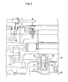
- Fig. 2 is a drawing showing a section of a check valve by enlarging a part of a vehicular power transmission of an embodiment
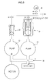
- Fig. 3 shows an oil passage of the check valve of the embodiment
- Fig. 4 are section views of the check valve, respectively.
- an input shaft 17 of a gear-change mechanical section 10 is connected to a crank shaft 2a of an engine 2 via a damper unit not shown and a carrier CR1 of a power distributing planetary gear 5 that is a simple planetary gear is connected to the input shaft 17 via a hub member 18.
- the carrier CR1 has pinions P1 rotatably supported by side plates not shown.
- a rotor shaft 19 of a first motor 3 is connected to a sun gear S1 that gears with the pinions P1.
- a ring gear R1 is also connected to the pinions P1 and the ring gear R1 is connected with a drum-like supporting member 20 and is connected to a transmission shaft 21 via the supporting member 20.
- a stepped transmission 6 having a planetary gear unit 6a is connected to a rear end (right side in the figure) of the transmission shaft 21.
- a carrier CR2 of the planetary gear unit 6a is connected to the transmission shaft 21 via a hub member 22.
- the carrier CR2 has long pinions P2 and P4 and a short pinion P3 (referred to simply as a pinion P3 hereinafter).
- the pinion P2 of a small diameter part and the pinion P4 of a large diameter part are formed in a body as the long pinion and the pinion P3 gears with the pinion P2 of the small diameter part.
- the sun gear S2 gears with the pinion P3 and is connected with a rotor shaft 23 of a second motor 4.
- a friction plate of a first brake B1 that is a multi-plate brake is engaged with the hub member 24 in spline and the first brake B1 is freely anchored by line oil supplied from a regulator valve.
- the pinion P3 gears with a ring gear R2 and a friction plate of a second brake B2 that is a multi-plate brake is engaged with the ring gear R2 in spline.
- the second brake B2 is freely anchored by line oil supplied from the regulator valve.
- the transmission shaft 21 is connected to an output shaft 26 of the gear-change mechanical section 10, the output shaft 26 is linked with a differential unit via a coupling and a propeller shaft not shown and is further connected to driving wheels 16, rear wheels, via the differential unit and right and left driving shafts.
- the hybrid power transmission 1 While hydraulic pressure is supplied to a valve body 40 having each valve such as the regulator valve by a mechanical oil pump 11 that is powered by the engine 2 in order to operate the gear-change mechanical section 10 or to lubricate each sliding section, the hybrid power transmission 1 is provided with a motor-operated oil pump 12 that drives independently regardless of the mechanical oil pump 11.
- the motor-operated oil pump 12 is driven by an electric motor 13 to which electric power is supplied from an inverter for the motor-operated oil pump.
- the hybrid power transmission 1 that is in linkage with the engine 2 also stops, so that the motor-operated oil pump 12 is mainly driven when the hybrid power transmission 1 is in the stopped state to assure hydraulic pressure of a hydraulic control unit.
- the mechanical oil pump 11 and the motor-operated oil pump 12 are connected in parallel with respect to the hydraulic control unit, so that when the motor-operated oil pump 12 operates during when the mechanical oil pump 11 is stopped, the hydraulic pressure generated by the motor-operated oil pump 12 flows backward to the mechanical oil pump 11 and hydraulic pressure necessary for the hydraulic control unit cannot be supplied. As a measure for this, a hydraulic check valve 70 becomes necessary to prevent the hydraulic pressure from flowing backward to the mechanical oil pump 11.
- Fig. 2 shows a section of the check valve 70 by enlarging a part of the gear-change mechanical section 10.
- the check valve 70 is disposed in a valve body 41 fixed at a lower part of a mission case 41 such that its axial line is almost coincident with a direction of gravity.
- Oil pressurized by the mechanical oil pump 11 is supplied to an upper part of the check valve 70 via an oil passage not shown within the mission case 41.
- the pressurized oil then presses down a ball 73 that is a valve positioned at the upper part of the check valve 70 in the figure while compressing a spring 74.
- a gap is produced between a valve seat 72a of the valve case 72 and the ball 73, creating a passage where the oil flows.
- the flow passage of the oil will now be explained with reference to Fig. 3 .
- the oil 30 flowing in from a return passage from a hydraulic circuit and the oil 31 suctioned from an oil pan through a strainer are lead to the mechanical oil pump 11 and the motor-operated oil pump 12 connected in parallel.
- the both pumps 11 and 12 are arranged so that either one operates appropriately.
- the motor-operated oil pump 12 flows out the oil to the check valve 32 that is connected with an outflow port to supply to passages of a regulator passage 33 and a lubricant passage 34, i.e., to a side of hydraulic load.
- the check valve 70 that plays a role of one-way valve is interposed to prevent the oil from flowing into the short-circuit passage by shutting off the short-circuit of the hydraulic circuit.
- Fig. 4A is a section view of the check valve 70 in a direction of a side face thereof
- Fig. 4B is a plan section view of the check valve 70 taken along an A-A line
- Fig. 4C is a plan section view of the check valve 70 taken along a B-B line.
- the check valve 70 is composed of the cylindrical valve case 72 within which the passage is formed, the ball 73 disposed within the valve case 72 so as to be slidable in an axial direction, i.e., in a longitudinal direction of the valve case 72, the valve seat 72a that is formed at one end portion of the passage of the valve case 72 and that closes the passage when the ball 73 seats thereon, a spring 74 that urges the ball 73 so that it seats on the valve seat 72a and a spring seat 71 fixed on the axially opposite side from the valve seat 72a of the valve case 72.
- the valve case 72 has a screw thread 72c formed around an outer periphery of an upper part thereof and is fixed by screwing the supporting section 72c into a female screw (not shown) formed at an opening of the oil passage for supplying he.
- the lower part of the valve case 72 is inserted into an opening hole composing an oil passage for supplying hydraulic pressure of the valve body 40. It is noted that the opening of the oil passage for supplying hydraulic pressure of the mission case 41 is oil-tightly jointed with the oil passage for supplying hydraulic pressure of the valve body 40 and a flange 72d of the valve case 72 is oil-tightly jointed with the mission case 41.
- the check valve 70 is disposed so that its axial direction, i.e., the longitudinal direction thereof, almost coincides with a direction of gravity.
- An inflow port 72f and the valve seat 72a against which the ball 73 abuts are formed at the upper part of the valve case 72 and an oil-tight state or a state in which the oil is allowed to pass is brought about depending on moves of the ball 73.
- a plurality of (three for example) concave channels 72b are formed straightly along the axial direction on an inner peripheral face of the valve case 72 from the lower part of the valve seat 72a to a terminal of the valve case 72.
- the concave channel 72b becomes a passage for guiding the oil flowing from the valve seat 72a to the terminal of the valve case 72.
- a supporting section 72e formed to be concentric with the valve case 72 between the concave channels 72b, for slidably supporting the ball 73.
- These concave channels 72b and the supporting sections 72e form the passages and can also restrict the move of the ball 73 so that it is freely movable only along a radial center of the valve case 72 in the axial direction. Therefore, the ball 73 can seat on the valve seat 72a while keeping an axial center of the ball 73 to be always concentric with an axial center of a seat face of the valve seat 72a.
- the concave channel 72b becomes the passage, it is advantageous from an aspect of reducing loss resistance to be straight and to have a large sectional area, it is desirable to provide many concave channels 72b or to provide the concave channel 72b having a large sectional area.
- the supporting section 72e restricts the move of the ball 73 in the radial direction within the valve case 72, it is required to abut against the peripheral face of the ball 73 by contact points of at least three or more.
- the ball 73 is desirable to be globular ball from the necessity of bringing about the oil-tight state by sliding within the valve case 72 and by abutting against the valve seat 72a, it is also possible to adopt a round column whose face of abutment is a plane face, a circular cone whose face of abutment is a slope or a disk-like plain plate as long as it is possible to form the oil-tight state.
- the ball 73 is urged toward the valve seat 72aby the spring 74 supported by the spring seat 71 and the ball 73 abuts against the valve seat 72a in a normal state. The ball 73 slides and forms the passage only when force in a direction going against the urge is applied.
- One end portion of the spring 74 abuts against a spring seat 75 provided in the spring seat 71 and is disposed so as to cover an outer periphery of a stopper section 75a and is supported so as to be movable in the compressing direction of the spring 74. Meanwhile, the other end of the spring 74 abuts against the ball 73 by going against the gravity and the ball 73 moves in the vertical direction along the move of the spring 74. Because urging force of the spring 74 is determined by diameter of the spring wire and a number of windings, the wire diameter and the number of windings are determined so that the spring can exhibit the least urging force that enables the ball 73 to abut against the valve seat 72a.
- the spring seat 71 is inserted into the valve case 72 from the lower end of the valve case 72 together with the ball 73 and the spring 74, engages in a body with the supporting sections 72e that form the inner periphery of the valve case 72 and the engagement will not be disengaged even if hydraulic pressure acting within the valve case 72 is applied.
- the spring seat 71 has the spring seat 75 having a pedestal and smaller than the outer diameter of the spring seat 71 and the columnar stopper section 75a that extends from the spring seat 75.
- the spring seat 75 is the face against which the spring 74 abuts as described above and the stopper section 75a has an apex for restricting the vertical movement of the valve 73 at the upper end thereof.
- the ball 73 is restricted to move only between the valve seat 72a and the apex of the stopper section 75a to prevent the ball 73 from largely sliding within the valve case 72.
- a range of an inner wall face of the valve case 72 where the ball 73 restricted by the stopper section 75a slidably contacts from the valve seat, including the valve seat 72a is a guide part where eccentric abrasion may occur.
- the stopper section 75a has a perforated hole 76d that is formed penetrating through the spring seat 71 and heading axially the radial center to the vicinity of the apex of the stopper section 75a as a passage described later.
- the stopper section 75a also has a through hole 76b formed to guide the oil passed through the concave channel 72b of the valve case 72 to the through hole 76b by the side portion thereof.
- the oil passage may be formed straightly, in addition to that there are two routes of oil outflow passages of outflow ports 76b and 76c, the oil flown into the valve case 72 is guided to the outside without causing loss and loss of pressure otherwise caused in the check valve 70 may be suppressed to the minimum.
- the check valve interposed in the supplying fluid passage from the mechanical pump has been explained in the embodiment, the invention is also applicable to the check valve interposed in the supplying fluid passage from the motor-operated pump. Still more, although the invention has been applied to the hybrid transmission as a vehicular transmission, the invention is not limited to that and is applicable also other vehicular transmission such as an automatic transmission in the same manner.
- the present invention is provided in an oil circulating passage of a vehicular transmission and may be used to prevent oil from flowing backward.
Landscapes
- Engineering & Computer Science (AREA)
- Mechanical Engineering (AREA)
- General Engineering & Computer Science (AREA)
- Transportation (AREA)
- Chemical & Material Sciences (AREA)
- Combustion & Propulsion (AREA)
- Power Engineering (AREA)
- Check Valves (AREA)
- Control Of Transmission Device (AREA)
- Hybrid Electric Vehicles (AREA)
- General Details Of Gearings (AREA)
Abstract


Description
- The present invention relates to a vehicular power transmission such as a hybrid power transmission and automatic transmission and more specifically to a check valve interposed in an oil passage for supplying hydraulic pressure from an oil pump to a gear-change mechanism section.
- A hybrid power transmission having driving sources of internal combustion engine and an electric motor requires a motor-operated pump driven by the electric motor, beside a mechanical pump driven by the driving sources, in order to stop the driving sources in stopping the vehicle due to a signal and the like. Therefore, either one of the mechanical pump and the motor-operated pump operates and the other stops and it is necessary to interpose a check valve in a supplying passage for supplying hydraulic pressure from an hydraulic pump to a hydraulic system so as to prevent the hydraulic pressure from the operative hydraulic pump from escaping from the side of the stopped hydraulic pump as disclosed in
Japanese Patent Laid-open No. 2001-41066 - Specifically, the check valve is mostly disposed within a valve body adjacent to a case for storing a gear-change mechanical section because the hydraulic pressure is supplied from the mechanical pump disposed in the gear-change mechanical section to the valve body in which a regulator valve and the like is disposed in the supplying passage from the mechanical.
- While the check valve is arranged in general such that a ball of the check valve is stored in a hole formed in the valve body, the passage is closed when the ball is biased by a spring and seats on a valve seat and fluid flows through the passage by moving the ball by going against the spring as the hydraulic pressure acts on the passage, there is a case when the fluid flown into the passage flows in a direction crossing to a direction in which the ball is movable. For example, when the valve seat is formed in the case for storing the gear-change mechanical section, the fluid from the mechanical pump flows within the valve body from the valve seat by passing the passage formed in the case, moves the ball by going against the spring and flows within the valve body so as to cross the ball. Then, coupled with that a clearance from the hole for storing the ball is large, the ball eccentrically hits against the valve seat. As a result, a passage part (referred to as a guide part hereinafter) including the valve seat where the ball moves and slidably abuts eccentrically wears. Then, it becomes a cause of dropping durability of the check valve and a cause of leakage of pressure.
- Specifically, because the supplying passage of the mechanical pump becomes a passage of main line pressure in running the vehicle when the gear-change mechanical section is operative, the above-mentioned problem of durability is actualized relatively soon due to the problem that a large amount of fluid flows through the valve case. Then, there is a possibility that pressure loss becomes large and that fuel consumption drops.
- Then, it is an object of the invention is to provide a vehicular transmission that solves the above-mentioned problems by using a check valve arranged such that a ball will not eccentrically hit against a guide part.
- In order to achieve the above-mentioned object, according to the invention of
Claim 1, a vehicular power transmission (1) having a gear-change mechanical section (10) for shifting power from a driving source and outputting it to an output shaft (26) and a hydraulic system for supplying the hydraulic pressure from hydraulic pumps (11, 12) to the gear-change mechanical section (10) via a check valve (70), wherein: - the check valve (70) has a cylindrical valve case (72) in which a passage is formed, a ball (73) stored within the valve case (72) so as to freely movable in an axial direction of the case, a valve seat (72a) that is formed at one end portion of the passage in the valve case (72) and that closes the passage when the ball (73) seats thereon, a spring (74) for urging the ball (73) so as to seat on the valve seat (72a) and a spring seat (71) fixed to a part on the axially opposite side from the valve seat (72a) of the valve case (72) to support the spring (74); and
- is arranged such that fluid flown into the valve case from the valve seat (72a) flows along the axial direction of the valve case (72) and flows out of outflow ports (76a, 76c) and such that a direction of low of the fluid within the valve case almost coincides with the movable direction of the ball (73).
- According to the structure described above, the check valve in which the valve is stored in the valve case formed in a body with the valve seat is used, so that the move of the valve is restricted in the axial direction of the valve case and the flow of the fluid almost coincides with the movable direction of the valve. Accordingly, the valve will not eccentrically hit against a guide part including the valve seat (referred to typically as a valve seat hereinafter) and it becomes possible to prevent eccentric abrasion of the valve seat otherwise caused by the eccentric hitting and then to prolong the life of the check valve.
- According to the invention of
Claim 2, the vehicular transmission as set forth inClaim 1 is arranged such that the ball (73) is a ball;
the spring seat (71) is positioned on an inner diametric side of the spring (74) and has a stopper section (75a) for restricting the move of the ball; and
the valve case (72) is disposed so that the axial direction, i.e., a longitudinal direction of the case almost coincides with a direction of gravity. - According to the structure described above, e ball is used as the valve and the stopper section restricts a movable range of the ball. Therefore, the movable direction of the ball almost coincides with the direction of gravity, no load otherwise caused by the gravity will not act on the ball and it becomes possible to prevent the ball from eccentrically hitting against the valve seat more steadily while keeping the move of the valve (ball) within the valve case to be smooth.
- According to the invention of Claim 3, the vehicular transmission as set forth in
Claim 1 is a transmission for hybrid vehicle which has an internal combustion engine (2) and electric motors (3) and (4) as the driving sources;
hydraulic pumps for supplying the hydraulic pressure to the hydraulic system are a mechanical oil pump (11) driven by the internal combustion engine (2) and a motor-operated oil pump (12) driven by the electric motors; and
the check valve (70) is interposed in a supplying oil passage for supplying the hydraulic pressure from the mechanical oil pump (11). - According to the structure described above, the check valve is applied to the supplying oil passage from the mechanical pump that is a main oil passage of the transmission for hybrid vehicles, so that it is possible to solve the problems concerning the durability of the check valve, to prevent pressure loss from increasing and to keep high performance of fuel consumption for a long period of time.
- According to the invention of Claim 4, the vehicular transmission as set forth in
Claim 1 is arranged such that the hydraulic system has a valve body (40) containing a plurality of valves and oil passages;
the valve body (40) is disposed at a lower part of the mission case (41) for storing the gear-change mechanical section (10); and
the valve case (72) is fixed to the mission case (41) and the check valve (70) is disposed between the mission case (41) and the valve body (40) such that its longitudinal direction conforms to a vertical direction. - According to the structure described above, the check valve is fixed to the case of the gear-change mechanical section and is disposed between the valve body such that the longitudinal direction of the check valve conforms to the vertical direction, so that it becomes possible to prevent the eccentric abrasion of the valve from occurring.
- According to the invention of Claim 5, the vehicular transmission as set forth in
Claims 1 is arranged such that a concave channel (72b) that becomes a passage of the fluid is formed along the axial line on an inner peripheral face of the valve case (72) and
the ball (73) is movable while contacting with the inner peripheral face of the valve case (72). - According to the structure described above, the concave channels formed on the inner peripheral face of the valve case become the passages and the ball can move along the axial line accurately while contacting with the inner peripheral face of the valve case, so that it is possible to steadily prevent the eccentric abrasion from occurring.
- According to the invention of Claim 6, the vehicular transmission (1) as set forth in Claim 5 is arranged such that there is provided with a plurality of concave channels (72b) and a plurality of outflow ports (76a), (76c) of the check valve.
- According to the structure described above, there are the plurality of concave channels and outflow ports, so that it is possible to smooth the flow of the fluid in the check valve and to prevent pressure loss from increasing.
- According to the invention of Claim 7, the vehicular transmission (1) as set forth in Claim 6 is arranged such that the outflow port is composed of an opening (76a) formed between the valve case (72) and the spring seat (75) and a hole (76b) formed within the stopper section.
- According to the structure described above, the outflow port is the opening continuous to the concave channel, so that the flow of the fluid in the check valve is smooth. Still more, the holes are made through the stopper section as outflow ports, the flow of the fluid becomes smoother.
- According to the invention of Claim 8, the vehicular transmission as set forth in
Claim 1 is arranged such that it has a case for storing the gear-change mechanical section;
the hydraulic system has the valve body (40) for storing the plurality of valves and the oil passages; and
the check valve (70) is separately made from the valve body (40) and the valve case (72) is fixed to the mission case (41) for storing the gear-change mechanical section (10) . - According to the structure described above, the check valve is separately made from the valve body and is fixed to the case for storing the automatic gear-change mechanical section, so that it is possible to prevent an oil amount within the valve case from being unbalanced in assembling the valve body to the case.
- It is noted that the reference numerals within the above parentheses are appended for the purpose of collating with the drawings and they do not influence the composition of Claims by any means.
-
-
Fig. 1 is a schematic drawing of a driving system of a hybrid vehicle of the invention. -
Fig. 2 is a drawing showing a section of a check valve by enlarging a part of a vehicular power transmission of an embodiment. -
Fig. 3 shows an oil passage of the check valve of the embodiment. -
Fig. 4 is a section view of the check valve. - A mode for carrying out the invention will be explained along
Figs. 1 through 4 .Fig. 1 is a schematic drawing of a driving system of a hybrid vehicle of the invention,Fig. 2 is a drawing showing a section of a check valve by enlarging a part of a vehicular power transmission of an embodiment,Fig. 3 shows an oil passage of the check valve of the embodiment andFig. 4 are section views of the check valve, respectively. - A structure of a hybrid transmission to which the invention is applied will be explained wit reference to
Fig. 1 at first. In thehybrid power transmission 1, aninput shaft 17 of a gear-changemechanical section 10 is connected to a crank shaft 2a of anengine 2 via a damper unit not shown and a carrier CR1 of a power distributing planetary gear 5 that is a simple planetary gear is connected to theinput shaft 17 via ahub member 18. The carrier CR1 has pinions P1 rotatably supported by side plates not shown. Arotor shaft 19 of a first motor 3 is connected to a sun gear S1 that gears with the pinions P1. A ring gear R1 is also connected to the pinions P1 and the ring gear R1 is connected with a drum-like supportingmember 20 and is connected to atransmission shaft 21 via the supportingmember 20. - Meanwhile, a stepped transmission 6 having a
planetary gear unit 6a is connected to a rear end (right side in the figure) of thetransmission shaft 21. Specifically, a carrier CR2 of theplanetary gear unit 6a is connected to thetransmission shaft 21 via ahub member 22. The carrier CR2 has long pinions P2 and P4 and a short pinion P3 (referred to simply as a pinion P3 hereinafter). The pinion P2 of a small diameter part and the pinion P4 of a large diameter part are formed in a body as the long pinion and the pinion P3 gears with the pinion P2 of the small diameter part. - The sun gear S2 gears with the pinion P3 and is connected with a
rotor shaft 23 of a second motor 4. A sun gear S3 gears with the pinion P4 and is connected with ahub member 24. A friction plate of a first brake B1 that is a multi-plate brake is engaged with thehub member 24 in spline and the first brake B1 is freely anchored by line oil supplied from a regulator valve. - The pinion P3 gears with a ring gear R2 and a friction plate of a second brake B2 that is a multi-plate brake is engaged with the ring gear R2 in spline. The second brake B2 is freely anchored by line oil supplied from the regulator valve.
- Then, the
transmission shaft 21 is connected to anoutput shaft 26 of the gear-changemechanical section 10, theoutput shaft 26 is linked with a differential unit via a coupling and a propeller shaft not shown and is further connected to drivingwheels 16, rear wheels, via the differential unit and right and left driving shafts. - While hydraulic pressure is supplied to a
valve body 40 having each valve such as the regulator valve by amechanical oil pump 11 that is powered by theengine 2 in order to operate the gear-changemechanical section 10 or to lubricate each sliding section, thehybrid power transmission 1 is provided with a motor-operatedoil pump 12 that drives independently regardless of themechanical oil pump 11. The motor-operatedoil pump 12 is driven by anelectric motor 13 to which electric power is supplied from an inverter for the motor-operated oil pump. When theengine 2 is idling or is stopped in starting for example, thehybrid power transmission 1 that is in linkage with theengine 2 also stops, so that the motor-operatedoil pump 12 is mainly driven when thehybrid power transmission 1 is in the stopped state to assure hydraulic pressure of a hydraulic control unit. - The
mechanical oil pump 11 and the motor-operatedoil pump 12 are connected in parallel with respect to the hydraulic control unit, so that when the motor-operatedoil pump 12 operates during when themechanical oil pump 11 is stopped, the hydraulic pressure generated by the motor-operatedoil pump 12 flows backward to themechanical oil pump 11 and hydraulic pressure necessary for the hydraulic control unit cannot be supplied. As a measure for this, ahydraulic check valve 70 becomes necessary to prevent the hydraulic pressure from flowing backward to themechanical oil pump 11. - Next, a structure of the check valve 70 (backflow preventing valve) of the invention will be explained.
Fig. 2 shows a section of thecheck valve 70 by enlarging a part of the gear-changemechanical section 10. Thecheck valve 70 is disposed in avalve body 41 fixed at a lower part of amission case 41 such that its axial line is almost coincident with a direction of gravity. Oil pressurized by themechanical oil pump 11 is supplied to an upper part of thecheck valve 70 via an oil passage not shown within themission case 41. The pressurized oil then presses down aball 73 that is a valve positioned at the upper part of thecheck valve 70 in the figure while compressing aspring 74. Then, a gap is produced between avalve seat 72a of thevalve case 72 and theball 73, creating a passage where the oil flows. - Meanwhile, when pressure of the passage on the side of the mechanical pump is relatively negative with respect to the hydraulic control unit, the oil flows into the
check valve 70 from a lower part thereof in the figure and theball 73 in thecheck valve 70 abuts against thevalve seat 72a of thevalve case 72 in linkage with the flow of the oil. Thus, it becomes possible to shut off the oil flow passage and to prevent the oil from flowing backward. - The flow passage of the oil will now be explained with reference to
Fig. 3 . Theoil 30 flowing in from a return passage from a hydraulic circuit and theoil 31 suctioned from an oil pan through a strainer are lead to themechanical oil pump 11 and the motor-operatedoil pump 12 connected in parallel. The both pumps 11 and 12 are arranged so that either one operates appropriately. For example, when themechanical oil pump 11 stops and the motor-operatedoil pump 12 operates due to idling stop, the motor-operatedoil pump 12 flows out the oil to thecheck valve 32 that is connected with an outflow port to supply to passages of aregulator passage 33 and alubricant passage 34, i.e., to a side of hydraulic load. - Meanwhile, because a short-circuit passage to the original oil flow-in passage via the
check valve 70 and the stoppedmechanical pump 11 is branched beside the supplyingpassages check valve 70 that plays a role of one-way valve is interposed to prevent the oil from flowing into the short-circuit passage by shutting off the short-circuit of the hydraulic circuit. - Next, a mechanism of the
check valve 70 will be explained.Fig. 4A is a section view of thecheck valve 70 in a direction of a side face thereof,Fig. 4B is a plan section view of thecheck valve 70 taken along an A-A line andFig. 4C is a plan section view of thecheck valve 70 taken along a B-B line. Thecheck valve 70 is composed of thecylindrical valve case 72 within which the passage is formed, theball 73 disposed within thevalve case 72 so as to be slidable in an axial direction, i.e., in a longitudinal direction of thevalve case 72, thevalve seat 72a that is formed at one end portion of the passage of thevalve case 72 and that closes the passage when theball 73 seats thereon, aspring 74 that urges theball 73 so that it seats on thevalve seat 72a and aspring seat 71 fixed on the axially opposite side from thevalve seat 72a of thevalve case 72. - The
valve case 72 has ascrew thread 72c formed around an outer periphery of an upper part thereof and is fixed by screwing the supportingsection 72c into a female screw (not shown) formed at an opening of the oil passage for supplying he. The lower part of thevalve case 72 is inserted into an opening hole composing an oil passage for supplying hydraulic pressure of thevalve body 40. It is noted that the opening of the oil passage for supplying hydraulic pressure of themission case 41 is oil-tightly jointed with the oil passage for supplying hydraulic pressure of thevalve body 40 and aflange 72d of thevalve case 72 is oil-tightly jointed with themission case 41. Then, in a state when thevalve case 72 is thus mounted, thecheck valve 70 is disposed so that its axial direction, i.e., the longitudinal direction thereof, almost coincides with a direction of gravity. Aninflow port 72f and thevalve seat 72a against which theball 73 abuts are formed at the upper part of thevalve case 72 and an oil-tight state or a state in which the oil is allowed to pass is brought about depending on moves of theball 73. Further, a plurality of (three for example)concave channels 72b are formed straightly along the axial direction on an inner peripheral face of thevalve case 72 from the lower part of thevalve seat 72a to a terminal of thevalve case 72. Theconcave channel 72b becomes a passage for guiding the oil flowing from thevalve seat 72a to the terminal of thevalve case 72. There is provided a supportingsection 72e, formed to be concentric with thevalve case 72 between theconcave channels 72b, for slidably supporting theball 73. Theseconcave channels 72b and the supportingsections 72e form the passages and can also restrict the move of theball 73 so that it is freely movable only along a radial center of thevalve case 72 in the axial direction. Therefore, theball 73 can seat on thevalve seat 72a while keeping an axial center of theball 73 to be always concentric with an axial center of a seat face of thevalve seat 72a. Still more, because theconcave channel 72b becomes the passage, it is advantageous from an aspect of reducing loss resistance to be straight and to have a large sectional area, it is desirable to provide manyconcave channels 72b or to provide theconcave channel 72b having a large sectional area. Meanwhile, from the necessity that the supportingsection 72e restricts the move of theball 73 in the radial direction within thevalve case 72, it is required to abut against the peripheral face of theball 73 by contact points of at least three or more. There is a mutual relationship between the area of theconcave channel 72b and a number of the supportingsection 72c and it must be appropriately selected from the oil passing loss resistance and mobility of theball 73. - Next, while the
ball 73 is desirable to be globular ball from the necessity of bringing about the oil-tight state by sliding within thevalve case 72 and by abutting against thevalve seat 72a, it is also possible to adopt a round column whose face of abutment is a plane face, a circular cone whose face of abutment is a slope or a disk-like plain plate as long as it is possible to form the oil-tight state. However, it is desirable to adopt the shape of the ball in order to reduce loss resistance without hampering a streamline along which the oil flows. Still more, theball 73 is urged toward the valve seat 72aby thespring 74 supported by thespring seat 71 and theball 73 abuts against thevalve seat 72a in a normal state. Theball 73 slides and forms the passage only when force in a direction going against the urge is applied. - One end portion of the
spring 74 abuts against aspring seat 75 provided in thespring seat 71 and is disposed so as to cover an outer periphery of astopper section 75a and is supported so as to be movable in the compressing direction of thespring 74. Meanwhile, the other end of thespring 74 abuts against theball 73 by going against the gravity and theball 73 moves in the vertical direction along the move of thespring 74. Because urging force of thespring 74 is determined by diameter of the spring wire and a number of windings, the wire diameter and the number of windings are determined so that the spring can exhibit the least urging force that enables theball 73 to abut against thevalve seat 72a. - Next, the
spring seat 71 is inserted into thevalve case 72 from the lower end of thevalve case 72 together with theball 73 and thespring 74, engages in a body with the supportingsections 72e that form the inner periphery of thevalve case 72 and the engagement will not be disengaged even if hydraulic pressure acting within thevalve case 72 is applied. Thespring seat 71 has thespring seat 75 having a pedestal and smaller than the outer diameter of thespring seat 71 and thecolumnar stopper section 75a that extends from thespring seat 75. Thespring seat 75 is the face against which thespring 74 abuts as described above and thestopper section 75a has an apex for restricting the vertical movement of thevalve 73 at the upper end thereof. Thereby, theball 73 is restricted to move only between thevalve seat 72a and the apex of thestopper section 75a to prevent theball 73 from largely sliding within thevalve case 72. It is noted that a range of an inner wall face of thevalve case 72 where theball 73 restricted by thestopper section 75a slidably contacts from the valve seat, including thevalve seat 72a, is a guide part where eccentric abrasion may occur. Still more, thestopper section 75a has a perforatedhole 76d that is formed penetrating through thespring seat 71 and heading axially the radial center to the vicinity of the apex of thestopper section 75a as a passage described later. Thestopper section 75a also has a throughhole 76b formed to guide the oil passed through theconcave channel 72b of thevalve case 72 to the throughhole 76b by the side portion thereof. - The oil flown into the
valve case 72 via theinflow port 72f and through the gap between thevalve seat 72a and theball 73 partially passes through theconcave channel 72b of thevalve case 72 and flows out of thevalve case 72 from theoutflow port 76a that corresponds to the lower end of theconcave channel 72b. A part thereof is guided to theperforated hole 76d via a throughhole 76b provided in thestopper section 75a and is flown out of thevalve case 72 from theperforated hole 76d via the throughhole 76b provided in thestopper section 75a. Thereby, the oil passage may be formed straightly, in addition to that there are two routes of oil outflow passages ofoutflow ports valve case 72 is guided to the outside without causing loss and loss of pressure otherwise caused in thecheck valve 70 may be suppressed to the minimum. - It is noted that although the check valve interposed in the supplying fluid passage from the mechanical pump has been explained in the embodiment, the invention is also applicable to the check valve interposed in the supplying fluid passage from the motor-operated pump. Still more, although the invention has been applied to the hybrid transmission as a vehicular transmission, the invention is not limited to that and is applicable also other vehicular transmission such as an automatic transmission in the same manner.
- The present invention is provided in an oil circulating passage of a vehicular transmission and may be used to prevent oil from flowing backward.
Claims (8)
- A vehicular power transmission having a gear-change mechanism section for shifting power from a driving source and outputting it to an output shaft and a hydraulic system for supplying hydraulic pressure from an oil pump to said gear-change mechanism section via a check valve,
said check valve has a cylindrical valve case in which a passage is formed, a ball stored within said valve case so as to freely movable in an axial direction of said case, a valve seat that is formed at one end portion of the passage in said valve case and that closes the passage when said ball seats thereon, a spring for urging said ball so as to seat on said valve seat and a spring seat fixed to a part on the axially opposite side from said valve seat of said valve case to support said spring; and
is arranged such that fluid flown into said valve case from said valve seat flows along the axial direction of said valve case and flows out of outflow ports and such that a direction of low of the fluid within said valve case almost coincides with the movable direction of said ball. - The vehicular transmission as set forth in Claim 1, wherein said is a ball;
said spring seat is positioned on an inner diametric side of said spring and has a stopper section for restricting the move of said ball; and
said valve case is disposed so that the axial direction, i.e., a longitudinal direction of the case almost coincides with a direction of gravity. - The vehicular transmission as set forth in Claim 1, wherein said vehicular transmission is a transmission for hybrid vehicle which has an internal combustion engine and electric motors as said driving sources;
hydraulic pumps for supplying the hydraulic pressure to said hydraulic system are a mechanical oil pump driven by said internal combustion engine and a motor-operated oil pump driven by the electric motors; and
said check valve is interposed in a supplying oil passage for supplying the hydraulic pressure from said mechanical oil pump. - The vehicular transmission as set forth in Claim 1, wherein said hydraulic system has a valve body containing a plurality of valves and oil passages;
said valve body is disposed at a lower part of said mission case for storing said gear-change mechanical section; and
said valve case is fixed to said mission case and said check valve is disposed between said mission case and said valve body such that its longitudinal direction conforms to a vertical direction. - The vehicular transmission as set forth in Claim 1, wherein a concave channel that becomes a passage of the fluid is formed along the axial line on an inner peripheral face of said valve case and
said ball is movable while contacting with the inner peripheral face of said valve case. - The vehicular transmission as set forth in Claim 5, further comprising a plurality of concave channels and a plurality of outflow ports of said check valve.
- The vehicular transmission as set forth in Claim 6, wherein said outflow port is composed of an opening formed between said valve case and said spring seat and a hole formed within said stopper section.
- The vehicular transmission as set forth in Claim 1, comprising a case for storing said gear-change mechanical section; wherein
said hydraulic system has said valve body for storing the plurality of valves and the oil passages; and
said check valve is separately made from said valve body and said valve case is fixed to said mission case for storing said gear-change mechanical section.
Applications Claiming Priority (2)
| Application Number | Priority Date | Filing Date | Title |
|---|---|---|---|
| JP2005333250A JP4499021B2 (en) | 2005-11-17 | 2005-11-17 | Transmission device for vehicles |
| PCT/JP2006/321206 WO2007058055A1 (en) | 2005-11-17 | 2006-10-25 | Transmission device for vehicle |
Publications (3)
| Publication Number | Publication Date |
|---|---|
| EP1909007A1 true EP1909007A1 (en) | 2008-04-09 |
| EP1909007A4 EP1909007A4 (en) | 2014-06-04 |
| EP1909007B1 EP1909007B1 (en) | 2015-09-09 |
Family
ID=38048445
Family Applications (1)
| Application Number | Title | Priority Date | Filing Date |
|---|---|---|---|
| EP06822183.7A Ceased EP1909007B1 (en) | 2005-11-17 | 2006-10-25 | Transmission device for vehicle |
Country Status (7)
| Country | Link |
|---|---|
| US (1) | US8287425B2 (en) |
| EP (1) | EP1909007B1 (en) |
| JP (1) | JP4499021B2 (en) |
| KR (1) | KR100923077B1 (en) |
| CN (1) | CN101243275B (en) |
| RU (1) | RU2380241C2 (en) |
| WO (1) | WO2007058055A1 (en) |
Cited By (1)
| Publication number | Priority date | Publication date | Assignee | Title |
|---|---|---|---|---|
| DE102015223804A1 (en) * | 2015-12-01 | 2017-06-01 | Zf Friedrichshafen Ag | Hydraulic control for an automatic transmission |
Families Citing this family (24)
| Publication number | Priority date | Publication date | Assignee | Title |
|---|---|---|---|---|
| JP5182066B2 (en) * | 2008-12-22 | 2013-04-10 | 日産自動車株式会社 | Fluid pressure circuit structure of transmission |
| KR101134734B1 (en) | 2009-10-30 | 2012-04-13 | 기아자동차주식회사 | Hydraulic Circuit of Transmission for Hybrid Vehicle |
| JP5407905B2 (en) * | 2010-01-29 | 2014-02-05 | 株式会社ジェイテクト | Hydraulic supply device |
| KR101163699B1 (en) * | 2010-06-24 | 2012-07-09 | 기아자동차주식회사 | Check valve for hydraulic system of automatic transmission |
| JP5510360B2 (en) * | 2011-02-22 | 2014-06-04 | アイシン・エィ・ダブリュ株式会社 | Vehicle transmission |
| BR112014002571A2 (en) * | 2011-08-03 | 2017-02-21 | Toyota Motor Co Ltd | switching valve |
| DE112014003695B4 (en) * | 2013-09-30 | 2018-09-13 | Aisin Aw Co., Ltd. | Vehicle hydraulic supply device |
| JP6292057B2 (en) * | 2014-07-07 | 2018-03-14 | トヨタ自動車株式会社 | Hydraulic supply device for vehicles |
| JP6128082B2 (en) * | 2014-09-08 | 2017-05-17 | トヨタ自動車株式会社 | Vehicle hydraulic control device |
| US9643481B2 (en) | 2015-05-20 | 2017-05-09 | Ford Global Technologies, Llc | Multi-mode powersplit hybrid transmission |
| US9694663B2 (en) | 2015-07-24 | 2017-07-04 | Ford Global Technologies, Llc | Hybrid transmission |
| DE102015221891A1 (en) * | 2015-11-06 | 2017-05-11 | Continental Automotive Gmbh | Conveying device for conveying oil |
| US20190024808A1 (en) * | 2016-02-25 | 2019-01-24 | Aisin Aw Co., Ltd. | Valve part and method of manufacturing valve part |
| CN106015661A (en) * | 2016-08-02 | 2016-10-12 | 陈艳艳 | Compact threaded connection one-way valve |
| CN106151607A (en) * | 2016-08-02 | 2016-11-23 | 陈艳艳 | Threaded check valve |
| CN106015662A (en) * | 2016-08-02 | 2016-10-12 | 陈艳艳 | Threaded connection one-way valve |
| CN106151608A (en) * | 2016-08-02 | 2016-11-23 | 陈艳艳 | The threaded check valve of compact |
| US10082196B2 (en) | 2016-09-01 | 2018-09-25 | Ford Global Technologies, Llc | Hybrid transaxle |
| US11486509B2 (en) * | 2018-12-04 | 2022-11-01 | Honda Motor Co., Ltd. | Check valve, check valve mechanism, and hydraulic system |
| JP7182441B2 (en) * | 2018-12-05 | 2022-12-02 | 日本電産トーソク株式会社 | hydraulic controller |
| US11511642B2 (en) | 2019-04-05 | 2022-11-29 | Oshkosh Corporation | Electric concrete vehicle systems and methods |
| EP4567279A3 (en) | 2019-10-11 | 2025-11-12 | Oshkosh Corporation | Operational modes for hybrid fire fighting vehicle |
| KR20210109709A (en) | 2020-02-27 | 2021-09-07 | 삼성디스플레이 주식회사 | Display device |
| US11506110B2 (en) * | 2020-05-18 | 2022-11-22 | Schaeffler Technologies AG & Co. KG | Oil-spray tube with poppet valve |
Family Cites Families (22)
| Publication number | Priority date | Publication date | Assignee | Title |
|---|---|---|---|---|
| SU125148A1 (en) * | 1959-06-06 | 1959-11-30 | А.А. Благонравов | Gear shift mechanism for machine transmissions |
| JPH01113676A (en) | 1987-10-27 | 1989-05-02 | Nec Corp | Inspecting method of high-output field effect transistor |
| JPH01113676U (en) * | 1988-01-27 | 1989-07-31 | ||
| JPH0477070U (en) * | 1990-11-19 | 1992-07-06 | ||
| RU2020242C1 (en) * | 1992-04-20 | 1994-09-30 | Специализированное проектно-конструкторское и технологическое бюро ТПСТО "Спецтранс" | Hybrid drive for vehicle |
| JP2916732B2 (en) * | 1992-12-16 | 1999-07-05 | 株式会社テイエルブイ | Check valve for liquid |
| US5801499A (en) * | 1995-07-11 | 1998-09-01 | Aisin Aw Co., Ltd. | Control system for a vehicular drive unit |
| DE19622123A1 (en) * | 1996-06-01 | 1997-12-04 | Schaeffler Waelzlager Kg | No=return valve |
| DE19739904A1 (en) * | 1997-09-11 | 1999-03-18 | Bosch Gmbh Robert | Check valve, especially for a piston pump |
| JP3551845B2 (en) | 1999-07-28 | 2004-08-11 | トヨタ自動車株式会社 | Vehicle control device |
| JP4433536B2 (en) * | 1999-12-27 | 2010-03-17 | トヨタ自動車株式会社 | Vehicle control device |
| JP2001280458A (en) * | 2000-03-31 | 2001-10-10 | Mitsubishi Motors Corp | Vehicle hydraulic supply system |
| JP3864753B2 (en) * | 2001-10-23 | 2007-01-10 | トヨタ自動車株式会社 | Lubrication device |
| JP2003240104A (en) | 2002-02-14 | 2003-08-27 | Aisin Aw Co Ltd | Automatic transmission |
| JP4200679B2 (en) * | 2002-02-18 | 2008-12-24 | アイシン・エィ・ダブリュ株式会社 | Vehicle control device |
| DE20213267U1 (en) * | 2002-08-29 | 2002-12-05 | Wagner Gmbh & Co Fahrzeugteilefabrik, 36043 Fulda | Pressure relief valve |
| JP3783716B2 (en) * | 2004-01-22 | 2006-06-07 | トヨタ自動車株式会社 | Control device for hybrid vehicle |
| JP3783714B2 (en) * | 2004-01-22 | 2006-06-07 | トヨタ自動車株式会社 | Control device for hybrid vehicle |
| JP4145250B2 (en) * | 2004-01-27 | 2008-09-03 | トヨタ自動車株式会社 | Hybrid vehicle drive system |
| JP4661078B2 (en) * | 2004-04-26 | 2011-03-30 | アイシン精機株式会社 | Hydraulic supply device |
| JP4205026B2 (en) * | 2004-09-01 | 2009-01-07 | 本田技研工業株式会社 | Hydraulic supply device for transmission |
| US7285066B2 (en) * | 2005-09-01 | 2007-10-23 | General Motors Corporation | Multiplexed trim valve system for an electrically variable hybrid transmission |
-
2005
- 2005-11-17 JP JP2005333250A patent/JP4499021B2/en not_active Expired - Fee Related
-
2006
- 2006-10-25 CN CN2006800305944A patent/CN101243275B/en not_active Expired - Fee Related
- 2006-10-25 EP EP06822183.7A patent/EP1909007B1/en not_active Ceased
- 2006-10-25 WO PCT/JP2006/321206 patent/WO2007058055A1/en not_active Ceased
- 2006-10-25 RU RU2008106909/11A patent/RU2380241C2/en not_active IP Right Cessation
- 2006-10-25 KR KR1020087004332A patent/KR100923077B1/en not_active Expired - Fee Related
- 2006-11-16 US US11/600,230 patent/US8287425B2/en not_active Expired - Fee Related
Cited By (2)
| Publication number | Priority date | Publication date | Assignee | Title |
|---|---|---|---|---|
| DE102015223804A1 (en) * | 2015-12-01 | 2017-06-01 | Zf Friedrichshafen Ag | Hydraulic control for an automatic transmission |
| DE102015223804B4 (en) | 2015-12-01 | 2019-12-19 | Zf Friedrichshafen Ag | Hydraulic control for an automatic transmission and method for assembling a hydraulic control unit |
Also Published As
| Publication number | Publication date |
|---|---|
| US8287425B2 (en) | 2012-10-16 |
| KR20080037047A (en) | 2008-04-29 |
| EP1909007B1 (en) | 2015-09-09 |
| JP2007139060A (en) | 2007-06-07 |
| JP4499021B2 (en) | 2010-07-07 |
| RU2380241C2 (en) | 2010-01-27 |
| KR100923077B1 (en) | 2009-10-22 |
| US20070151546A1 (en) | 2007-07-05 |
| WO2007058055A1 (en) | 2007-05-24 |
| CN101243275B (en) | 2012-06-13 |
| EP1909007A4 (en) | 2014-06-04 |
| RU2008106909A (en) | 2009-08-27 |
| CN101243275A (en) | 2008-08-13 |
Similar Documents
| Publication | Publication Date | Title |
|---|---|---|
| EP1909007B1 (en) | Transmission device for vehicle | |
| US8303468B2 (en) | Power transmission device and vehicle having the same | |
| US8454477B2 (en) | Power transmitting device and vehicle having same mounted thereon | |
| US8147364B2 (en) | Flow rate regulation valve, rotating body, and belt-type stepless transmission | |
| US8652008B2 (en) | Power transmission apparatus | |
| US8636483B2 (en) | Pump apparatus, power transmission apparatus, and vehicle | |
| US8413783B2 (en) | Power transmission device and vehicle having the same | |
| US8539850B2 (en) | Power transmission device and vehicle having the same | |
| US8312895B2 (en) | Solenoid valve device | |
| JP2015503711A (en) | Drive system and electric vehicle equipped with the drive system | |
| US8984874B2 (en) | Power transmission device | |
| US20180112767A1 (en) | Transmission packaging for an epicyclic/planetary gearbox unit with integrated oil pump | |
| US6810772B2 (en) | Automatic transmission | |
| US9777830B2 (en) | Power transmission device | |
| JP2007170533A (en) | Lubricator for vehicles | |
| US6805655B2 (en) | Oil pressure control mechanism for automatic transmission | |
| US9982773B2 (en) | Power transmission device | |
| JP2019158049A (en) | Hydraulic control device and its control method | |
| US10753464B2 (en) | Switch valve assembly and hydraulic control module including same | |
| JP4618048B2 (en) | Belt type continuously variable transmission | |
| JP2010164177A (en) | Power transmitting device and vehicle having power transmitting device mounted thereon | |
| WO2018168970A1 (en) | Hydraulic control device | |
| JP2011214613A (en) | Automatic transmission | |
| JP2007247563A (en) | Oil pump and vehicle transmission device using oil pump |
Legal Events
| Date | Code | Title | Description |
|---|---|---|---|
| PUAI | Public reference made under article 153(3) epc to a published international application that has entered the european phase |
Free format text: ORIGINAL CODE: 0009012 |
|
| 17P | Request for examination filed |
Effective date: 20080131 |
|
| AK | Designated contracting states |
Kind code of ref document: A1 Designated state(s): DE FR GB |
|
| RBV | Designated contracting states (corrected) |
Designated state(s): DE FR GB |
|
| DAX | Request for extension of the european patent (deleted) | ||
| RAP1 | Party data changed (applicant data changed or rights of an application transferred) |
Owner name: TOYOTA JIDOSHA KABUSHIKI KAISHA Owner name: AISIN AW CO., LTD. |
|
| A4 | Supplementary search report drawn up and despatched |
Effective date: 20140506 |
|
| RIC1 | Information provided on ipc code assigned before grant |
Ipc: F16H 61/00 20060101ALI20140428BHEP Ipc: F16K 15/04 20060101AFI20140428BHEP |
|
| REG | Reference to a national code |
Ref country code: DE Ref legal event code: R079 Ref document number: 602006046614 Country of ref document: DE Free format text: PREVIOUS MAIN CLASS: F16K0015040000 Ipc: B60K0006387000 |
|
| RIC1 | Information provided on ipc code assigned before grant |
Ipc: B60K 6/445 20071001ALI20150113BHEP Ipc: B60K 6/387 20071001AFI20150113BHEP Ipc: F16H 61/00 20060101ALI20150113BHEP Ipc: F16K 15/04 20060101ALI20150113BHEP |
|
| GRAP | Despatch of communication of intention to grant a patent |
Free format text: ORIGINAL CODE: EPIDOSNIGR1 |
|
| INTG | Intention to grant announced |
Effective date: 20150402 |
|
| GRAS | Grant fee paid |
Free format text: ORIGINAL CODE: EPIDOSNIGR3 |
|
| GRAA | (expected) grant |
Free format text: ORIGINAL CODE: 0009210 |
|
| RIN1 | Information on inventor provided before grant (corrected) |
Inventor name: OMOTE, KENJI Inventor name: ADACHI, MASATOSHI Inventor name: WAKUTA, SATORU Inventor name: FUJIKAWA, MASATO Inventor name: KAWAKAMI, SHINJI |
|
| AK | Designated contracting states |
Kind code of ref document: B1 Designated state(s): DE FR GB |
|
| REG | Reference to a national code |
Ref country code: GB Ref legal event code: FG4D |
|
| REG | Reference to a national code |
Ref country code: FR Ref legal event code: PLFP Year of fee payment: 10 |
|
| REG | Reference to a national code |
Ref country code: DE Ref legal event code: R096 Ref document number: 602006046614 Country of ref document: DE |
|
| REG | Reference to a national code |
Ref country code: DE Ref legal event code: R097 Ref document number: 602006046614 Country of ref document: DE |
|
| PLBE | No opposition filed within time limit |
Free format text: ORIGINAL CODE: 0009261 |
|
| STAA | Information on the status of an ep patent application or granted ep patent |
Free format text: STATUS: NO OPPOSITION FILED WITHIN TIME LIMIT |
|
| 26N | No opposition filed |
Effective date: 20160610 |
|
| REG | Reference to a national code |
Ref country code: FR Ref legal event code: PLFP Year of fee payment: 11 |
|
| REG | Reference to a national code |
Ref country code: FR Ref legal event code: PLFP Year of fee payment: 12 |
|
| REG | Reference to a national code |
Ref country code: FR Ref legal event code: PLFP Year of fee payment: 13 |
|
| PGFP | Annual fee paid to national office [announced via postgrant information from national office to epo] |
Ref country code: FR Payment date: 20180913 Year of fee payment: 13 |
|
| PGFP | Annual fee paid to national office [announced via postgrant information from national office to epo] |
Ref country code: DE Payment date: 20181009 Year of fee payment: 13 |
|
| PGFP | Annual fee paid to national office [announced via postgrant information from national office to epo] |
Ref country code: GB Payment date: 20181024 Year of fee payment: 13 |
|
| REG | Reference to a national code |
Ref country code: DE Ref legal event code: R119 Ref document number: 602006046614 Country of ref document: DE |
|
| PG25 | Lapsed in a contracting state [announced via postgrant information from national office to epo] |
Ref country code: DE Free format text: LAPSE BECAUSE OF NON-PAYMENT OF DUE FEES Effective date: 20200501 |
|
| GBPC | Gb: european patent ceased through non-payment of renewal fee |
Effective date: 20191025 |
|
| PG25 | Lapsed in a contracting state [announced via postgrant information from national office to epo] |
Ref country code: FR Free format text: LAPSE BECAUSE OF NON-PAYMENT OF DUE FEES Effective date: 20191031 Ref country code: GB Free format text: LAPSE BECAUSE OF NON-PAYMENT OF DUE FEES Effective date: 20191025 |