EP1908985A1 - Amortisseur magnétorhéologique bi-tube - Google Patents
Amortisseur magnétorhéologique bi-tube Download PDFInfo
- Publication number
- EP1908985A1 EP1908985A1 EP06291551A EP06291551A EP1908985A1 EP 1908985 A1 EP1908985 A1 EP 1908985A1 EP 06291551 A EP06291551 A EP 06291551A EP 06291551 A EP06291551 A EP 06291551A EP 1908985 A1 EP1908985 A1 EP 1908985A1
- Authority
- EP
- European Patent Office
- Prior art keywords
- valve
- fluid
- chamber
- piston
- cylinder
- Prior art date
- Legal status (The legal status is an assumption and is not a legal conclusion. Google has not performed a legal analysis and makes no representation as to the accuracy of the status listed.)
- Withdrawn
Links
- 239000012530 fluid Substances 0.000 claims abstract description 60
- 230000006835 compression Effects 0.000 claims abstract description 43
- 238000007906 compression Methods 0.000 claims abstract description 43
- 238000013016 damping Methods 0.000 claims abstract description 24
- 230000003068 static effect Effects 0.000 claims description 7
- 238000006073 displacement reaction Methods 0.000 claims description 3
- 238000011144 upstream manufacturing Methods 0.000 claims description 2
- 239000007789 gas Substances 0.000 description 23
- 230000036316 preload Effects 0.000 description 3
- IJGRMHOSHXDMSA-UHFFFAOYSA-N Atomic nitrogen Chemical compound N#N IJGRMHOSHXDMSA-UHFFFAOYSA-N 0.000 description 2
- 230000000694 effects Effects 0.000 description 2
- 241001503987 Clematis vitalba Species 0.000 description 1
- 239000006096 absorbing agent Substances 0.000 description 1
- 230000006978 adaptation Effects 0.000 description 1
- 230000002457 bidirectional effect Effects 0.000 description 1
- 239000004020 conductor Substances 0.000 description 1
- 230000007423 decrease Effects 0.000 description 1
- 230000006866 deterioration Effects 0.000 description 1
- 239000011261 inert gas Substances 0.000 description 1
- 238000002955 isolation Methods 0.000 description 1
- 239000002184 metal Substances 0.000 description 1
- 229910052757 nitrogen Inorganic materials 0.000 description 1
- 238000004806 packaging method and process Methods 0.000 description 1
- 230000035939 shock Effects 0.000 description 1
- 239000007787 solid Substances 0.000 description 1
- 239000000725 suspension Substances 0.000 description 1
Images


Classifications
-
- F—MECHANICAL ENGINEERING; LIGHTING; HEATING; WEAPONS; BLASTING
- F16—ENGINEERING ELEMENTS AND UNITS; GENERAL MEASURES FOR PRODUCING AND MAINTAINING EFFECTIVE FUNCTIONING OF MACHINES OR INSTALLATIONS; THERMAL INSULATION IN GENERAL
- F16F—SPRINGS; SHOCK-ABSORBERS; MEANS FOR DAMPING VIBRATION
- F16F9/00—Springs, vibration-dampers, shock-absorbers, or similarly-constructed movement-dampers using a fluid or the equivalent as damping medium
- F16F9/32—Details
- F16F9/53—Means for adjusting damping characteristics by varying fluid viscosity, e.g. electromagnetically
- F16F9/535—Magnetorheological [MR] fluid dampers
-
- F—MECHANICAL ENGINEERING; LIGHTING; HEATING; WEAPONS; BLASTING
- F16—ENGINEERING ELEMENTS AND UNITS; GENERAL MEASURES FOR PRODUCING AND MAINTAINING EFFECTIVE FUNCTIONING OF MACHINES OR INSTALLATIONS; THERMAL INSULATION IN GENERAL
- F16F—SPRINGS; SHOCK-ABSORBERS; MEANS FOR DAMPING VIBRATION
- F16F9/00—Springs, vibration-dampers, shock-absorbers, or similarly-constructed movement-dampers using a fluid or the equivalent as damping medium
- F16F9/10—Springs, vibration-dampers, shock-absorbers, or similarly-constructed movement-dampers using a fluid or the equivalent as damping medium using liquid only; using a fluid of which the nature is immaterial
- F16F9/14—Devices with one or more members, e.g. pistons, vanes, moving to and fro in chambers and using throttling effect
- F16F9/16—Devices with one or more members, e.g. pistons, vanes, moving to and fro in chambers and using throttling effect involving only straight-line movement of the effective parts
- F16F9/18—Devices with one or more members, e.g. pistons, vanes, moving to and fro in chambers and using throttling effect involving only straight-line movement of the effective parts with a closed cylinder and a piston separating two or more working spaces therein
- F16F9/185—Bitubular units
- F16F9/187—Bitubular units with uni-directional flow of damping fluid through the valves
Definitions
- the present invention relates generally to a magnetorheological (MR) damper and in particular a twin-tube MR damper for controlling the movement of vehicle suspension systems.
- MR magnetorheological
- Conventional piston dampers typically comprise a cylinder containing a non-compressible fluid, such as oil, and a piston slideably mounted within the cylinder and attached to a distal end of a piston rod extending out of an end of the cylinder.
- the fluid within the cylinder passes through one or more orifices of the piston providing damping of relative motion between the piston/piston rod and the cylinder.
- Piston dampers are used as shock absorbers on automobiles and on other vehicles. Piston dampers also are used to provide motion resistance on exercise equipment such as stair climbers and rowing machines.
- a compressible gas is located inside the cylinder and is typically isolated from the fluid by a moveable wall defining a gas chamber to accommodate the displacement of fluid caused by the movement of the piston rod into and out of the cylinder.
- a static pressure for the compressible gas in the gas chamber of between 20-30 bar is required to avoid cavitation during movement of the piston, particularly in compression of the damper.
- the high static pressure necessary for damper operation undesirably increases friction which decreases desired motion isolation and undesirably pre-loads the mounting system.
- Such known arrangement is typically referred to as a mono-tube damper.
- an outer tube surrounds and is in fluid communication with the cylinder, the fluid passing through the outer cylinder rather than through apertures in the piston during movement of the piston. This allows the pressure in the gas chamber to be reduced to around 5 bar. A low static pressure considerably reduces friction and pre-load the mounting system.
- Such system is known as a twin-tube damper.
- the damping force in compression and rebound is determined by the size and number of flow apertures in the piston. Often it is desirable to vary the damping force during operation of the vehicle to suit different driving conditions. To achieve such variable damping effect, it is known to provide dampers having a cylinder containing an MR fluid and having an MR piston slideably mounted within the cylinder. The MR fluid passes through an orifice of the MR piston. Exposing the MR fluid in the orifice to a varying magnetic field, generated by providing a varying electric current to an electric coil of the MR piston, varies the damping effect of the MR fluid in the orifice providing variably-controlled damping of relative motion between the MR piston and the cylinder. The electric current applied to the coil is varied to accommodate varying operating conditions.
- a compressible gas is located inside a gas chamber In the cylinder defined by a moveable wall separating the gas from the MR fluid.
- a rod attached to the MR piston extends away from the moveable wall and outside the cylinder.
- the cylinder and the rod are attached to separate structures to dampen relative motion of the two structures along the direction of piston travel.
- the gas chamber must be pressurised to a high pressure to pre-charge the fluid within the cylinder.
- the requirement for electrical conductors from the coil to be passed through the piston rod frequently leads to problems due to the limited packaging space around the upper end of the piston rod.
- US 6695102 discloses a MR twin-tube damper wherein the MR fluid valve is mounted within a lower region of the cylinder rather than in the piston, such MR valve controlling the flow of fluid between the inner and outer tubes during movement of the piston within the inner tube or cylinder. This enables the wiring to be simplified since electrical connections can be provided on the side of the cylinder where there is less space restriction.
- the piston is solid with no fluid flow therethrough, damping force being provided by restriction of the flow of fluid through the MR valve, the flow through the MR valve being bidirectional. Therefore, when the damper is in compression, the pressure downstream of the MR valve, between the upper side of the piston and the MR valve, is reduced, leading to a risk of cavitation unless the gas pressure is increased to mono-tube pressures to pre-load the MR fluid.
- a damping device comprising a cylinder containing a volume of magnetorheological fluid therein, said cylinder having a piston slidably mounted therein, said piston dividing said cylinder into a compression chamber and a rebound chamber, the piston being connected to a distal end of a piston rod, said piston rod extending out of the cylinder through the rebound chamber, an MR valve being provided in a flow path for controlling the flow of fluid from said rebound chamber to said compression chamber, at least one first one way valve being provided In said piston for allowing the flow of fluid through said piston from said compression chamber to said rebound chamber while preventing the flow of fluid through said piston from said rebound chamber to said compression chamber, at least one second one way valve being provided in said flow path for allowing the flow of fluid from said rebound chamber to said compression chamber through said MR valve while preventing the return flow of fluid from said compression chamber to said further chamber through said MR valve.
- At least one second one way valve is provided downstream of said MR valve.
- a compressible gas is provided in a region of said flow path or in a reservoir communicating with said flow path downstream of said MR valve.
- said compressible gas is isolated from said MR fluid by means of a movable wall or diaphragm.
- the static pressure of said compressible gas is between atmospheric and 10 bar, more preferably between atmospheric and 5 bar.
- said MR valve divides said flow path into a first region upstream of said MR valve, said first region communicating with said rebound chamber, and a second region downstream of said MR valve communicating with said compression chamber.
- At least a portion of said flow path is defined between an outer wall of the cylinder and an outer tube concentrically arranged around at least a portion of said outer wall.
- the MR valve may be provided at or adjacent a side region of said outer wall.
- the MR valve is arranged coaxially with said cylinder.
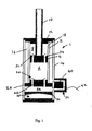
- the piston 4 is connected to one end of a piston rod 10, the piston rod 10 extending through the rebound chamber 8 and out of the damper body 1 through an aperture in an end wall 12 of the damper body 1.
- An outer tube 14 is arranged concentrically around the inner tube 2 to define an outer chamber 16 between the inner and outer tubes. At least one inlet passage 18 is provided in an upper wall of the inner tube 2 whereby the rebound chamber 8 is in fluid communication with the outer chamber 16.
- a lower wall 20 of the compression chamber 6 is provided with a plurality of passageways 22 whereby the compression chamber 6 can be placed in fluid communication with a lower chamber 24.
- Each passageway 22 is provided with a lower one way valve 26 allowing MR fluid to flow through the passageway 22 from the lower chamber 24 to the compression chamber 6 while preventing the flow of fluid through the passageway 22 from the compression chamber 6 to the lower chamber 24.
- a lower portion of the lower chamber 24 defines a gas chamber 28 containing a compressible- gas, preferably an inert gas such as nitrogen, the gas chamber 28 being separated from the remainder of the lower chamber 24 by means of a moveable wall 30. It is envisaged that the moveable wall may be omitted if not required, for example if the damper is to be mounted "upside down" with respect to the orientation shown in the drawings.
- a compressible- gas preferably an inert gas such as nitrogen
- the displacement of fluid caused by movement of the piston rod into the cylinder may be accommodated by an accumulator, such as a metal bellows or spring loaded piston communicating with the lower chamber 24, instead of a compressible gas.
- an accumulator such as a metal bellows or spring loaded piston communicating with the lower chamber 24, instead of a compressible gas.
- Fluid communication between the outer chamber 16 and the lower chamber 24 is provided by means of an MR valve 32 mounted on a side of the damper body 1.
- the MR valve 32 includes an electromagnetic coil 40 for applying a magnetic field to MR fluid passing though one or more passageways through the MR valve as is conventional in the art.
- Electrical connections 42 are provided for supplying current to the coil 40 of the MR valve to control the flow of fluid therethrough.
- compression and rebound chambers, outer chamber and the region of the lower chamber above the moveable wall together define a closed fluid circuit which is filled with MR fluid.
- the piston 4 is provided with a plurality of axial through passageways 34, each passageway 34 being provided with an upper one way valve 36 whereby MR fluid can flow through the passageways 34 from the compression chamber 6 to the rebound chamber 8 but is prevented from flowing through the passageways 34 from the rebound chamber 8 to the compression chamber 6.
- flow through the MR valve is uni-directional by virtue of the one way valves 26,36 which only permit flow of fluid from the compression chamber 6 into rebound chamber 8 and from the lower chamber 24 into the compression chamber 6 such that fluid can only flow through the MR valve 32 from the outer chamber 16 to the lower chamber 24 in one direction.
- the lower one-way valves 26 close, preventing MR fluid from flowing through the passageways 22, while the upper one-way valves 36 on the piston 4 open whereby MR fluid flows through the passageways 34 from the compression chamber 6 into the rebound chamber 8.
- the volume of fluid displaced due to the movement of the piston rod 10 into the rebound chamber 8 flows into the outer chamber 16 through the inlet passage 18 and from there through the MR valve into the lower chamber 24 wherein the moveable wall 30 can move against the compressible gas in the gas chamber 28.
- the upper one-way valve 36 closes and MR fluid is pushed by the piston through the inlet passage 18 and into the outer chamber 16. As in compression, the fluid then passes through the MR valve and into the lower chamber 24 before passing into the compression chamber 6 through the passageways 22.
- the compression damping and the rebound damping are independently determined and controlled by the MR valve.
- asymmetric compression/rebound damping control is achieved.
- the flow through the MR valve is unidirectional the gas pressure in the gas chamber 28 can be low, reducing the static loading on the seals and bushings of the damper leading to reduced damper friction, improving ride comfort at low damping force conditions (i.e. low MR valve coil current).
- the unidirectional flow also reduces the risk of cavitation at high piston velocity in compression.
- the circulation of the MR fluid through the damper by virtue of the one way valves improves thermal dissipation and hence reduces deterioration of the MR fluid, increasing the life of the fluid.
- the side location of the MR valve facilitates the provision of electrical connections to the coil of the MR valve and reduces the overall length of the damper.
- a damper according to a second embodiment of the present invention is illustrated in Fig. 2.
- the MR valve 32 is provided below the rebound chamber coaxial with the piston rod 10.
- Such arrangement provides more efficient (i.e. straighter) flow paths for the MR fluid through the MR valve 32 at the expense of overall damper length (increased "dead length").
- Fig 3 shows a further adaptation of the damper arrangement of Fig 2, wherein the gas chamber 28 is provided in a remote reservoir 50 communicating with a lower chamber 24 of smaller volume.
- Such arrangement reduces the overall length of the damper, in particular the "dead length", and further facilitates electrical connection of the coil of the MR valve.
- bypass flow can be provided by allowing a predetermined return flow effectively bypassing each of the one way valves.
- the bypass flow can be provided by a passage or leak path allowing a predetermined flow from the compression chamber 6 into the lower chamber 24, thus bypassing the lower one-way valve 26.
- the bypass flow can be provided by a passage or leak path in the piston 4 allowing a predetermined flow from the rebound rebound chamber 8 into the compression chamber 6, effectively bypassing the upper one-way valve 36.
Landscapes
- Engineering & Computer Science (AREA)
- General Engineering & Computer Science (AREA)
- Mechanical Engineering (AREA)
- Physics & Mathematics (AREA)
- Electromagnetism (AREA)
- Fluid-Damping Devices (AREA)
Priority Applications (1)
| Application Number | Priority Date | Filing Date | Title |
|---|---|---|---|
| EP06291551A EP1908985A1 (fr) | 2006-10-02 | 2006-10-02 | Amortisseur magnétorhéologique bi-tube |
Applications Claiming Priority (1)
| Application Number | Priority Date | Filing Date | Title |
|---|---|---|---|
| EP06291551A EP1908985A1 (fr) | 2006-10-02 | 2006-10-02 | Amortisseur magnétorhéologique bi-tube |
Publications (1)
| Publication Number | Publication Date |
|---|---|
| EP1908985A1 true EP1908985A1 (fr) | 2008-04-09 |
Family
ID=37845254
Family Applications (1)
| Application Number | Title | Priority Date | Filing Date |
|---|---|---|---|
| EP06291551A Withdrawn EP1908985A1 (fr) | 2006-10-02 | 2006-10-02 | Amortisseur magnétorhéologique bi-tube |
Country Status (1)
| Country | Link |
|---|---|
| EP (1) | EP1908985A1 (fr) |
Cited By (24)
| Publication number | Priority date | Publication date | Assignee | Title |
|---|---|---|---|---|
| JP2012193764A (ja) * | 2011-03-15 | 2012-10-11 | Sanwa Tekki Corp | 磁気粘性流体流動型制振装置 |
| WO2013059951A1 (fr) * | 2011-10-27 | 2013-05-02 | Pontificia Universidad Catolica De Chile | Amortisseur magnéto-rhéologique |
| CN103322113A (zh) * | 2013-05-31 | 2013-09-25 | 重庆大学 | 基于磁流变材料的可控力矩装置 |
| CN103591209A (zh) * | 2013-11-08 | 2014-02-19 | 青岛农业大学 | 七级可调的往复式电流变液阻尼器 |
| WO2014032795A1 (fr) * | 2012-08-28 | 2014-03-06 | Inventus Engineering Gmbh | Amortisseur |
| CN103644248A (zh) * | 2013-12-13 | 2014-03-19 | 江苏大学 | 可控惯容和阻尼磁流变惯容器装置及其控制方法 |
| WO2014122526A3 (fr) * | 2013-02-07 | 2015-06-25 | Technip France | Compensateur de pilonnement passif |
| CN104747649A (zh) * | 2015-04-20 | 2015-07-01 | 中国人民解放军装甲兵工程学院 | 一种磁流变阻尼器 |
| WO2014122527A3 (fr) * | 2013-02-07 | 2015-07-02 | Technip France | Compensateur de pilonnement passif |
| EP2703686A3 (fr) * | 2012-08-28 | 2015-12-30 | DT Swiss AG | Fourche suspendue, en particulier pour vélos |
| FR3042445A1 (fr) * | 2015-10-14 | 2017-04-21 | Peugeot Citroen Automobiles Sa | Suspension a ressort metallique et hydropneumatique pour vehicule |
| CZ306693B6 (cs) * | 2015-11-16 | 2017-05-10 | ÄŚVUT v Praze, Fakulta strojnĂ | Hydraulický tlumič |
| CN107061603A (zh) * | 2017-03-21 | 2017-08-18 | 哈尔滨工程大学 | 一种新型磁流变液多级调控隔振器 |
| WO2018108930A1 (fr) * | 2016-12-12 | 2018-06-21 | Inventus Engineering Gmbh | Élément de porte pourvu d'un dispositif amortisseur commandable contenant un fluide magnétorhéologique |
| CN108533665A (zh) * | 2018-06-04 | 2018-09-14 | 清华大学 | 可快速再分散沉降颗粒的磁流变减振器 |
| CN110043599A (zh) * | 2019-05-08 | 2019-07-23 | 中南大学 | 可定位磁流变柔性加载装置 |
| CN110925349A (zh) * | 2019-11-26 | 2020-03-27 | 重庆大学 | 自传感分离式双筒磁流变阻尼器 |
| CN111156277A (zh) * | 2020-03-06 | 2020-05-15 | 江苏容大减震科技股份有限公司 | 基于流体、压缩原理的串联式阻尼器及其工作方法 |
| CN111219437A (zh) * | 2020-01-20 | 2020-06-02 | 同济大学 | 一种可回收能量的磁流变颗粒阻尼器 |
| CN113757297A (zh) * | 2021-09-09 | 2021-12-07 | 重庆交通大学 | 基于u形线圈的磁流变减振器 |
| CN114458717A (zh) * | 2022-01-04 | 2022-05-10 | 浙江路得坦摩汽车部件股份有限公司 | 一种缸体内腔自补偿式磁流变阻尼器 |
| CN116181834A (zh) * | 2023-02-23 | 2023-05-30 | 北京京西重工有限公司 | 阻尼器组件 |
| WO2025039719A1 (fr) * | 2023-08-18 | 2025-02-27 | 上海曼杰汽车精密零部件有限公司 | Amortisseur et véhicule |
| US12604133B2 (en) | 2024-03-20 | 2026-04-14 | Dell Products Lp | System and method of assembling an adjustable clamping ear cup assembly for an audio headset |
Citations (4)
| Publication number | Priority date | Publication date | Assignee | Title |
|---|---|---|---|---|
| EP0261427A2 (fr) * | 1986-09-25 | 1988-03-30 | Robert Bosch Gmbh | Amortisseur de choc bitubulaire |
| JPH06272732A (ja) * | 1993-03-17 | 1994-09-27 | Natl Res Inst For Metals | 減衰力可変型緩衝器 |
| WO2001016503A1 (fr) * | 1999-08-28 | 2001-03-08 | Er Fluid Developments Limited | Soupape de commande et amortisseur hydraulique |
| US6695102B1 (en) | 2002-12-31 | 2004-02-24 | Lord Corporation | Magnetorheological twin-tube damping device |
-
2006
- 2006-10-02 EP EP06291551A patent/EP1908985A1/fr not_active Withdrawn
Patent Citations (4)
| Publication number | Priority date | Publication date | Assignee | Title |
|---|---|---|---|---|
| EP0261427A2 (fr) * | 1986-09-25 | 1988-03-30 | Robert Bosch Gmbh | Amortisseur de choc bitubulaire |
| JPH06272732A (ja) * | 1993-03-17 | 1994-09-27 | Natl Res Inst For Metals | 減衰力可変型緩衝器 |
| WO2001016503A1 (fr) * | 1999-08-28 | 2001-03-08 | Er Fluid Developments Limited | Soupape de commande et amortisseur hydraulique |
| US6695102B1 (en) | 2002-12-31 | 2004-02-24 | Lord Corporation | Magnetorheological twin-tube damping device |
Cited By (35)
| Publication number | Priority date | Publication date | Assignee | Title |
|---|---|---|---|---|
| JP2012193764A (ja) * | 2011-03-15 | 2012-10-11 | Sanwa Tekki Corp | 磁気粘性流体流動型制振装置 |
| WO2013059951A1 (fr) * | 2011-10-27 | 2013-05-02 | Pontificia Universidad Catolica De Chile | Amortisseur magnéto-rhéologique |
| CN104755795A (zh) * | 2012-08-28 | 2015-07-01 | 因文图斯工程有限公司 | 阻尼器 |
| EP2703686A3 (fr) * | 2012-08-28 | 2015-12-30 | DT Swiss AG | Fourche suspendue, en particulier pour vélos |
| WO2014032795A1 (fr) * | 2012-08-28 | 2014-03-06 | Inventus Engineering Gmbh | Amortisseur |
| WO2014122527A3 (fr) * | 2013-02-07 | 2015-07-02 | Technip France | Compensateur de pilonnement passif |
| WO2014122526A3 (fr) * | 2013-02-07 | 2015-06-25 | Technip France | Compensateur de pilonnement passif |
| US9702428B2 (en) | 2013-02-07 | 2017-07-11 | Technip France | Passive heave compensator |
| AU2014213685B2 (en) * | 2013-02-07 | 2017-03-30 | Technip France | Passive heave compensator |
| AU2014213755B2 (en) * | 2013-02-07 | 2017-04-20 | Technip France | Subsea Passive Heave Compensator |
| US9718652B2 (en) | 2013-02-07 | 2017-08-01 | Technip France | Passive heave compensator |
| CN103322113A (zh) * | 2013-05-31 | 2013-09-25 | 重庆大学 | 基于磁流变材料的可控力矩装置 |
| CN103591209A (zh) * | 2013-11-08 | 2014-02-19 | 青岛农业大学 | 七级可调的往复式电流变液阻尼器 |
| CN103644248A (zh) * | 2013-12-13 | 2014-03-19 | 江苏大学 | 可控惯容和阻尼磁流变惯容器装置及其控制方法 |
| CN103644248B (zh) * | 2013-12-13 | 2016-01-20 | 江苏大学 | 可控惯容和阻尼磁流变惯容器装置及其控制方法 |
| CN104747649A (zh) * | 2015-04-20 | 2015-07-01 | 中国人民解放军装甲兵工程学院 | 一种磁流变阻尼器 |
| FR3042445A1 (fr) * | 2015-10-14 | 2017-04-21 | Peugeot Citroen Automobiles Sa | Suspension a ressort metallique et hydropneumatique pour vehicule |
| CZ306693B6 (cs) * | 2015-11-16 | 2017-05-10 | ÄŚVUT v Praze, Fakulta strojnĂ | Hydraulický tlumič |
| WO2018108930A1 (fr) * | 2016-12-12 | 2018-06-21 | Inventus Engineering Gmbh | Élément de porte pourvu d'un dispositif amortisseur commandable contenant un fluide magnétorhéologique |
| CN107061603A (zh) * | 2017-03-21 | 2017-08-18 | 哈尔滨工程大学 | 一种新型磁流变液多级调控隔振器 |
| CN108533665A (zh) * | 2018-06-04 | 2018-09-14 | 清华大学 | 可快速再分散沉降颗粒的磁流变减振器 |
| CN110043599A (zh) * | 2019-05-08 | 2019-07-23 | 中南大学 | 可定位磁流变柔性加载装置 |
| CN110925349B (zh) * | 2019-11-26 | 2021-07-20 | 重庆大学 | 自传感分离式双筒磁流变阻尼器 |
| CN110925349A (zh) * | 2019-11-26 | 2020-03-27 | 重庆大学 | 自传感分离式双筒磁流变阻尼器 |
| US12228189B2 (en) | 2019-11-26 | 2025-02-18 | Chongqing University | Self-sensing and separated dual-cylinder magnetorheological damper |
| WO2021104185A1 (fr) * | 2019-11-26 | 2021-06-03 | 重庆大学 | Amortisseur magnétorhéologique à double cylindre séparé à détection automatique |
| CN111219437A (zh) * | 2020-01-20 | 2020-06-02 | 同济大学 | 一种可回收能量的磁流变颗粒阻尼器 |
| CN111219437B (zh) * | 2020-01-20 | 2021-07-20 | 同济大学 | 一种可回收能量的磁流变颗粒阻尼器 |
| CN111156277A (zh) * | 2020-03-06 | 2020-05-15 | 江苏容大减震科技股份有限公司 | 基于流体、压缩原理的串联式阻尼器及其工作方法 |
| CN113757297A (zh) * | 2021-09-09 | 2021-12-07 | 重庆交通大学 | 基于u形线圈的磁流变减振器 |
| CN114458717A (zh) * | 2022-01-04 | 2022-05-10 | 浙江路得坦摩汽车部件股份有限公司 | 一种缸体内腔自补偿式磁流变阻尼器 |
| CN114458717B (zh) * | 2022-01-04 | 2023-07-18 | 浙江路得坦摩汽车部件股份有限公司 | 一种缸体内腔自补偿式磁流变阻尼器 |
| CN116181834A (zh) * | 2023-02-23 | 2023-05-30 | 北京京西重工有限公司 | 阻尼器组件 |
| WO2025039719A1 (fr) * | 2023-08-18 | 2025-02-27 | 上海曼杰汽车精密零部件有限公司 | Amortisseur et véhicule |
| US12604133B2 (en) | 2024-03-20 | 2026-04-14 | Dell Products Lp | System and method of assembling an adjustable clamping ear cup assembly for an audio headset |
Similar Documents
| Publication | Publication Date | Title |
|---|---|---|
| EP1908985A1 (fr) | Amortisseur magnétorhéologique bi-tube | |
| US12420605B2 (en) | Shock absorber | |
| US6419058B1 (en) | Magnetorheological damper with piston bypass | |
| US7654369B2 (en) | Hydraulic vibration damper piston with an integral electrically operated adjustment valve | |
| US7878311B2 (en) | Piston with an integral electrically operated adjustment valve for a hydraulic vibration damper | |
| EP1016805B1 (fr) | Dispositifs à fluide magnétorhéologique | |
| US6419057B1 (en) | Power-off damping in MR damper | |
| US6131709A (en) | Adjustable valve and vibration damper utilizing same | |
| EP2258961B1 (fr) | Amortisseur de véhicule | |
| EP3569890A1 (fr) | Amortisseur de chocs et procédé pour commander un écoulement d'amortissement dans un amortisseur et utilisation de deux soupapes à commande électrique pour commander un écoulement d'amortissement dans un amortisseur | |
| US20120048665A1 (en) | Compression isolator for a suspension damper | |
| EP1975453A2 (fr) | Amortisseur de chocs à pression fluide réglable | |
| US20150047936A1 (en) | Amplitude sensitive hydraulic damper | |
| US20160160955A1 (en) | Suspension damper | |
| US10487902B2 (en) | Vibration damper for a motor vehicle | |
| US20120211318A1 (en) | Real-Time Variable Damping Module Using Magnetic Shape Memory Material | |
| US11719305B2 (en) | Balanced continuously semi-active damper | |
| EP4317738A1 (fr) | Amortisseur hydraulique | |
| US20020139624A1 (en) | Twin-tube magnetorheological damper | |
| US10480552B2 (en) | Accumulator with secondary gas chamber | |
| EP2770227A2 (fr) | Soupape de commande de force d'amortissement et amortisseur | |
| US6085877A (en) | Bi-Directional Multiple State Suspension Damper | |
| US6793048B1 (en) | Solenoid actuated continuously variable shock absorber | |
| US20250178398A1 (en) | Fluid pressure shock absorber |
Legal Events
| Date | Code | Title | Description |
|---|---|---|---|
| PUAI | Public reference made under article 153(3) epc to a published international application that has entered the european phase |
Free format text: ORIGINAL CODE: 0009012 |
|
| AK | Designated contracting states |
Kind code of ref document: A1 Designated state(s): AT BE BG CH CY CZ DE DK EE ES FI FR GB GR HU IE IS IT LI LT LU LV MC NL PL PT RO SE SI SK TR |
|
| AX | Request for extension of the european patent |
Extension state: AL BA HR MK RS |
|
| AKX | Designation fees paid | ||
| REG | Reference to a national code |
Ref country code: DE Ref legal event code: 8566 |
|
| STAA | Information on the status of an ep patent application or granted ep patent |
Free format text: STATUS: THE APPLICATION IS DEEMED TO BE WITHDRAWN |
|
| 18D | Application deemed to be withdrawn |
Effective date: 20081010 |