EP1908884A2 - Verfahren zur Durchführung von Abflussarbeiten, insbesondere zur Stabilisierung von Steigungen und/oder Geländeformationen, die unstabil oder abrutschgefährdet sind - Google Patents
Verfahren zur Durchführung von Abflussarbeiten, insbesondere zur Stabilisierung von Steigungen und/oder Geländeformationen, die unstabil oder abrutschgefährdet sind Download PDFInfo
- Publication number
- EP1908884A2 EP1908884A2 EP07018268A EP07018268A EP1908884A2 EP 1908884 A2 EP1908884 A2 EP 1908884A2 EP 07018268 A EP07018268 A EP 07018268A EP 07018268 A EP07018268 A EP 07018268A EP 1908884 A2 EP1908884 A2 EP 1908884A2
- Authority
- EP
- European Patent Office
- Prior art keywords
- drilling
- rod
- shaft
- drainage
- magazine
- Prior art date
- Legal status (The legal status is an assumption and is not a legal conclusion. Google has not performed a legal analysis and makes no representation as to the accuracy of the status listed.)
- Withdrawn
Links
Images


Classifications
-
- E—FIXED CONSTRUCTIONS
- E02—HYDRAULIC ENGINEERING; FOUNDATIONS; SOIL SHIFTING
- E02D—FOUNDATIONS; EXCAVATIONS; EMBANKMENTS; UNDERGROUND OR UNDERWATER STRUCTURES
- E02D17/00—Excavations; Bordering of excavations; Making embankments
- E02D17/20—Securing of slopes or inclines
-
- E—FIXED CONSTRUCTIONS
- E02—HYDRAULIC ENGINEERING; FOUNDATIONS; SOIL SHIFTING
- E02D—FOUNDATIONS; EXCAVATIONS; EMBANKMENTS; UNDERGROUND OR UNDERWATER STRUCTURES
- E02D3/00—Improving or preserving soil or rock, e.g. preserving permafrost soil
- E02D3/02—Improving by compacting
- E02D3/10—Improving by compacting by watering, draining, de-aerating or blasting, e.g. by installing sand or wick drains
-
- E—FIXED CONSTRUCTIONS
- E21—EARTH OR ROCK DRILLING; MINING
- E21B—EARTH OR ROCK DRILLING; OBTAINING OIL, GAS, WATER, SOLUBLE OR MELTABLE MATERIALS OR A SLURRY OF MINERALS FROM WELLS
- E21B19/00—Handling rods, casings, tubes or the like outside the borehole, e.g. in the derrick; Apparatus for feeding the rods or cables
- E21B19/20—Combined feeding from rack and connecting, e.g. automatically
-
- E—FIXED CONSTRUCTIONS
- E21—EARTH OR ROCK DRILLING; MINING
- E21B—EARTH OR ROCK DRILLING; OBTAINING OIL, GAS, WATER, SOLUBLE OR MELTABLE MATERIALS OR A SLURRY OF MINERALS FROM WELLS
- E21B7/00—Special methods or apparatus for drilling
- E21B7/02—Drilling rigs characterised by means for land transport with their own drive, e.g. skid mounting or wheel mounting
- E21B7/027—Drills for drilling shallow holes, e.g. for taking soil samples or for drilling postholes
Definitions
- This invention relates to a method for the stabilisation of slopes and/or terrain which are unstable or subject to landslides, by inserting suitable drainage devices.
- a vertical shaft with a concrete lining or a microtunnel is constructed in an area of ground predefined by a suitable geological study, and an automated drilling unit is positioned in the microtunnel or vertical shaft.
- Said drilling unit comprises at least one drilling head, a magazine of rods, and robotic devices able to pick up the rods from the magazine and take them to said drilling head, said rods being constituted by said drainage pipes; said head is then controlled to perform drilling operations, with simultaneous laying of the drainage pipe.
- said drainage pipes are constituted by a tubular steel element, the walls of which contain holes, each of which said holes houses a microfiltration valve. Said holes are filled with water-soluble material to prevent the passages from becoming obstructed during drilling; when the pipe has been laid, the water-soluble material dissolves, thus clearing said passages.
- shaft is used to indicate both a vertical shaft and a microtunnel.
- Drainage systems which involve inserting in the ground drainage pipes consisting of metal or plastic pipes containing holes for the passage of water.
- a number of said drainage pipes are inserted into the ground up to the required depth, spaced at a suitable distance apart.
- this innovation now offers a method for the stabilisation of unstable terrain and/or slopes by inserting drainage pipes.
- Said method involves the construction of a microtunnel or a vertical shaft in an area predefined by a suitable geological study, and the positioning in said microtunnel or vertical shaft of an automated drilling unit with equipment which, as the machine advances down the vertical shaft or along the microtunnel, drills through the concrete lining and inserts drainage pipes into the soil to be drained.
- Automated control systems and suitable video cameras allow the operators to check the machine remotely and to lay the necessary drainage pipes without having to access areas of unstable ground.
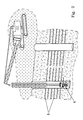
- Figure 1 illustrates the method according to the invention, wherein the machine is caused to advance along a microtunnel 1, which in the case illustrated is constructed below the main slip plane of the landslide movement and which is accessed, for example, from a vertical shaft 2.
- a microtunnel which in the case illustrated is constructed below the main slip plane of the landslide movement and which is accessed, for example, from a vertical shaft 2.
- Both the microtunnel and the vertical shaft have a lining consisting of a layer of concrete of suitable thickness.
- Robotic machine 4 which inserts drainage pipes 5 into the ground, moves on rack rails 3 laid in the microtunnel, which may be positioned laterally to the area to be drained or in another suitable area of stable ground.
- said drainage pipes also act as drilling rods, and are therefore fitted at the head with a sacrificial bit 6.
- Machine 4 consists of a drive unit 7 which, by means of electric motors, causes it to advance along rails 3, and a drilling unit 8, which said unit is illustrated in detail in figure 3.
- Figure 3 only shows the drilling unit, because the machine hangs from a structure that lowers it into a vertical shaft; a motor is therefore not required to control its advance.
- the structure of the machine shown as 10, is fitted with a magazine 11 holding a plurality of drainage pipes/drilling rods 12, and a robotic system 13 that picks up rods 12 from magazine 11 and takes them to a rotary head 14, which engages the rods, causes them to rotate, and pushes them forwards, running along a guide 15.
- machine 4 enters the tunnel and takes up a position in the area where the first pipe is to be laid.
- the operator can monitor the correct performance of the operations and manage the entire process of drilling and laying of drainage pipes remotely, from a control board.
- Said operation begins when robot 13 picks up a first drilling rod, called the "core barrel”, from magazine 11, and positions it on rotary head 14.
- the core barrel is replaced in the magazine, and the machine picks up the first rod or drainage pipe, which is suitably equipped with a disposable bit and a preventer (safety shutter) 20, and fits it on the rotary head. This starts the rotation of the unit, which advances and simultaneously drills the ground and inserts the preventer under pressure into the concrete wall of the microtunnel.
- a preventer safety shutter
- the machine When the first rod has been fully inserted, the machine automatically picks up a second rod from the magazine and loads it onto head 14 which, as it advances, screws it onto the rod already inserted in the ground and advances, continuing with drilling and inserting the second rod into the ground.
- the machine returns to the starting position.
- the operator loads a new set of rods into the magazine and then controls the advance of the machine to the point of insertion of the second drainage pipe, repeating all the operations described above.
- the method according to the invention involves inserting the machine into a vertical shaft or vertical tunnel, and repeating the same operations to insert a plurality of drainage pipes into the ground, but this time laying them substantially horizontally.
- the machine will be advantageously hung from a crane, so that it can be inserted in the vertical shaft.
- the drainage pipes consist of steel pipes of suitable thickness, with drainage holes having a diameter of approx. 10-20 mm. in the wall thereof, a microfiltration valve with holes having a diameter of approx. 1 mm being inserted into each hole.
- a possible example of said valves, illustrated in figure 4 is constituted by a threaded cap 16 which is screwed into hole 17 in the rod and which in turn contains a plurality of holes 18 for the passage of liquid.
- the body of cap 16 is hollow, for example with a cone-frustum-shaped cavity or, preferably, with an undercut.
- Said cavity is filled with a layer of water-soluble material 19, preferably water-soluble plastic, which also fills holes 17, preventing them from becoming obstructed by debris during the soil-drilling stage.
- a layer of water-soluble material 19 preferably water-soluble plastic, which also fills holes 17, preventing them from becoming obstructed by debris during the soil-drilling stage.
- the drainage pipe acts as a drilling rod at the drilling stage, because the microfiltration valves, effectively embedded in the steel pipe, are protected by the water-soluble plastic.
- This configuration also allows the drilling fluid directed towards the bit to be pumped through the rod at the necessary pressure, without any need for a specific pipe.
- the water-soluble plastic used to protect the valves is a polyvinyl-alcohol-based polymer which is water-soluble and biodegradable in a moist environment, and has proved particularly suitable for this type of application.
- the method according to the invention greatly simplifies the operation of drilling and laying of a drainage pipe, which is performed almost fully automatically without any risk to the operators, who can control all the operations while remaining outside the area of unstable ground.
- this method is mainly designed to stabilise landslide movements, it could also be effectively used in other applications, such as drainage of percolates in contaminated areas, to increase the uptake capacity of groundwater to be conveyed to aqueducts, or as a drilling system for the injection of grout and other mixtures, for the purpose of consolidation with the jet-grouting or conventional grouting technique.
Landscapes
- Engineering & Computer Science (AREA)
- Mining & Mineral Resources (AREA)
- Life Sciences & Earth Sciences (AREA)
- Geology (AREA)
- General Life Sciences & Earth Sciences (AREA)
- Environmental & Geological Engineering (AREA)
- Structural Engineering (AREA)
- Fluid Mechanics (AREA)
- Physics & Mathematics (AREA)
- Geochemistry & Mineralogy (AREA)
- Paleontology (AREA)
- Civil Engineering (AREA)
- General Engineering & Computer Science (AREA)
- Mechanical Engineering (AREA)
- Agronomy & Crop Science (AREA)
- Soil Sciences (AREA)
- Consolidation Of Soil By Introduction Of Solidifying Substances Into Soil (AREA)
- Pit Excavations, Shoring, Fill Or Stabilisation Of Slopes (AREA)
Applications Claiming Priority (1)
| Application Number | Priority Date | Filing Date | Title |
|---|---|---|---|
| IT000043A ITPC20060043A1 (it) | 2006-10-02 | 2006-10-02 | Metodo per la realizzazione di opere di drenaggio , in particolare per la stabilizzazione, di versanti e/o terreni instabili o franosi |
Publications (2)
| Publication Number | Publication Date |
|---|---|
| EP1908884A2 true EP1908884A2 (de) | 2008-04-09 |
| EP1908884A3 EP1908884A3 (de) | 2013-11-27 |
Family
ID=38691783
Family Applications (1)
| Application Number | Title | Priority Date | Filing Date |
|---|---|---|---|
| EP07018268.8A Withdrawn EP1908884A3 (de) | 2006-10-02 | 2007-09-18 | Verfahren zur Durchführung von Abflussarbeiten, insbesondere zur Stabilisierung von Steigungen und/oder Geländeformationen, die unstabil oder abrutschgefährdet sind |
Country Status (3)
| Country | Link |
|---|---|
| US (1) | US7455480B2 (de) |
| EP (1) | EP1908884A3 (de) |
| IT (1) | ITPC20060043A1 (de) |
Cited By (3)
| Publication number | Priority date | Publication date | Assignee | Title |
|---|---|---|---|---|
| ITPR20080081A1 (it) * | 2008-12-09 | 2010-06-10 | Tecnigest S R L | Apparato per perforazioni subacque |
| ITNA20120041A1 (it) * | 2012-07-31 | 2012-10-30 | Pietro Margiotta | Mac.mar. modello di strutture per contenimento delle terre,idrogeologicamente e ambientalmente conpatibile, economicamente ed agronomicamente vantaggioso |
| IT201800007633A1 (it) * | 2018-07-30 | 2020-01-30 | Clivio Srl | Sistema di drenaggio acqua |
Families Citing this family (11)
| Publication number | Priority date | Publication date | Assignee | Title |
|---|---|---|---|---|
| ITPC20060044A1 (it) * | 2006-10-02 | 2008-04-03 | Cesare Melegari | Tubo di drenaggio migliorato |
| US20140076530A1 (en) * | 2012-09-18 | 2014-03-20 | Alejandro Augusto Alvarez De Toledo | Facility with wells having multiple horizontal galleries for lowering water tables |
| JP2016037715A (ja) * | 2014-08-06 | 2016-03-22 | 新日鐵住金株式会社 | 地盤改良杭及び地盤改良工法 |
| JP6465297B2 (ja) * | 2015-03-25 | 2019-02-06 | 一般財団法人上越環境科学センター | 地下水排除施設用集水管、及び地下水排除施設用集水管におけるスライム付着防止方法 |
| JP6568393B2 (ja) * | 2015-05-01 | 2019-08-28 | 昌平 土橋 | 電位差式地下水排除施設用集水管及び地下水排除施設、並びにスライム付着防止方法 |
| CN107246019B (zh) * | 2017-06-30 | 2019-10-29 | 浙江大学 | 一种边坡地下水钻孔自启动负压排水方法 |
| CN107246008B (zh) * | 2017-06-30 | 2019-10-01 | 浙江大学 | 一种边坡防护的自排水锚索系统的施工方法 |
| US10738424B2 (en) | 2017-08-04 | 2020-08-11 | R&B Leasing, Llc | System and method for mitigating rockfalls |
| US11391005B2 (en) | 2017-08-04 | 2022-07-19 | R&B Leasing, Llc | System and method for mitigating rockfalls |
| CN111794238B (zh) * | 2020-07-20 | 2021-05-04 | 中铁二院工程集团有限责任公司 | 一种充填可溶晶体的注浆结构及施工方法 |
| CN114263260B (zh) * | 2022-01-19 | 2023-09-12 | 安徽禹舜建设工程有限公司 | 一种水利工程用大口径排水管道施工组件及施工方法 |
Family Cites Families (8)
| Publication number | Priority date | Publication date | Assignee | Title |
|---|---|---|---|---|
| US599719A (en) * | 1898-03-01 | Iethod of collecting and conveying water | ||
| US1142125A (en) * | 1914-01-17 | 1915-06-08 | Ephraim S Sooy | System and apparatus for the drainage and reclamation of inundated surfaces of land. |
| US1866826A (en) * | 1930-11-28 | 1932-07-12 | Strothmann Theodore | Hill draining system |
| DE973872C (de) * | 1953-05-29 | 1960-07-07 | Heinrich Scheven Fa | Verfahren zur Umlagerung der Kornanteile im Erdreich oder anderem verschiedenkoernigem Material |
| US3667236A (en) * | 1970-06-10 | 1972-06-06 | Dow Chemical Co | Method for treating subsurface soils |
| US4714376A (en) * | 1984-12-31 | 1987-12-22 | Jenab S Abdollah | Hillslope landslide stability drain |
| HUT65024A (en) * | 1986-03-21 | 1994-03-28 | Asszonyi | Method for building deep-level catchwater drain with comb-like suction tubes |
| US4988235A (en) * | 1988-04-27 | 1991-01-29 | Dennis Hurley | System for draining land areas through siphoning from a permeable catch basin |
-
2006
- 2006-10-02 IT IT000043A patent/ITPC20060043A1/it unknown
-
2007
- 2007-09-18 EP EP07018268.8A patent/EP1908884A3/de not_active Withdrawn
- 2007-10-02 US US11/905,535 patent/US7455480B2/en active Active - Reinstated
Cited By (4)
| Publication number | Priority date | Publication date | Assignee | Title |
|---|---|---|---|---|
| ITPR20080081A1 (it) * | 2008-12-09 | 2010-06-10 | Tecnigest S R L | Apparato per perforazioni subacque |
| ITNA20120041A1 (it) * | 2012-07-31 | 2012-10-30 | Pietro Margiotta | Mac.mar. modello di strutture per contenimento delle terre,idrogeologicamente e ambientalmente conpatibile, economicamente ed agronomicamente vantaggioso |
| IT201800007633A1 (it) * | 2018-07-30 | 2020-01-30 | Clivio Srl | Sistema di drenaggio acqua |
| EP3613944A1 (de) * | 2018-07-30 | 2020-02-26 | Clivio S.r.l. | Wasserdrainagevorrichtung |
Also Published As
| Publication number | Publication date |
|---|---|
| EP1908884A3 (de) | 2013-11-27 |
| US7455480B2 (en) | 2008-11-25 |
| US20080080931A1 (en) | 2008-04-03 |
| ITPC20060043A1 (it) | 2008-04-03 |
Similar Documents
| Publication | Publication Date | Title |
|---|---|---|
| US7455480B2 (en) | Method for the construction of drainage works, in particular for the stabilisation of slopes and/or terrain which are unstable or subject to landslides | |
| RU2712866C2 (ru) | Бурильная система с установкой для расширения ствола | |
| US5007770A (en) | Method and apparatus for constructing a subsurface retaining wall | |
| RU2331753C2 (ru) | Скважинный инструмент | |
| CN101139839B (zh) | 高承压水地区超深基坑的设置结构 | |
| JP2001115458A (ja) | 土留め壁を用いた深井戸構築工法 | |
| CN111519611B (zh) | 一种可横向连接钢筋笼的咬合桩施工方法 | |
| KR20100006754A (ko) | 흙막이공사의 케이싱 압입장치 및 이를 이용한 흙막이시공방법 | |
| ES3058392T3 (es) | Procedimiento para proporcionar una barrera subterránea para un embalse de agua | |
| KR20090115702A (ko) | 대구경 기초파일 시공을 위한 지반 굴착공법 | |
| KR100992513B1 (ko) | 다중 케이싱 천공에 의한 확장 대구경 타설 공법 | |
| CN116348655A (zh) | 材料和设备的地下部署方法和系统 | |
| JP4732287B2 (ja) | 井戸掘削装置 | |
| US8485281B2 (en) | Equipment for drilling secant holes | |
| JP4428888B2 (ja) | トンネル計画線上の地盤中の被圧水排水方法 | |
| JP2955120B2 (ja) | 排水用管路の敷設工法 | |
| CN104863188A (zh) | 自压重式抗浮施工方法 | |
| CN114856442B (zh) | 在土壤中制造地质钻孔的方法 | |
| GB2270329A (en) | Forming a hole in the ground | |
| WO2015009213A1 (en) | Method for boring holes and installing collection pipes in holes | |
| SU1747602A1 (ru) | Способ сооружени лучевых дрен | |
| NL1020304C2 (nl) | Werkwijze voor het aanbrengen van een diepwand in de grond. | |
| CN117822568A (zh) | 一种旋挖成孔灌注桩施工结构及其方法 | |
| JP3717228B2 (ja) | 防護工法 | |
| RU2339767C2 (ru) | Способ сооружения тоннеля под железнодорожной насыпью |
Legal Events
| Date | Code | Title | Description |
|---|---|---|---|
| PUAI | Public reference made under article 153(3) epc to a published international application that has entered the european phase |
Free format text: ORIGINAL CODE: 0009012 |
|
| AK | Designated contracting states |
Kind code of ref document: A2 Designated state(s): AT BE BG CH CY CZ DE DK EE ES FI FR GB GR HU IE IS IT LI LT LU LV MC MT NL PL PT RO SE SI SK TR |
|
| AX | Request for extension of the european patent |
Extension state: AL BA HR MK RS |
|
| PUAL | Search report despatched |
Free format text: ORIGINAL CODE: 0009013 |
|
| AK | Designated contracting states |
Kind code of ref document: A3 Designated state(s): AT BE BG CH CY CZ DE DK EE ES FI FR GB GR HU IE IS IT LI LT LU LV MC MT NL PL PT RO SE SI SK TR |
|
| AX | Request for extension of the european patent |
Extension state: AL BA HR MK RS |
|
| RIC1 | Information provided on ipc code assigned before grant |
Ipc: E02D 3/10 20060101AFI20131018BHEP Ipc: E02D 17/20 20060101ALI20131018BHEP |
|
| AKY | No designation fees paid | ||
| REG | Reference to a national code |
Ref country code: DE Ref legal event code: R108 |
|
| REG | Reference to a national code |
Ref country code: DE Ref legal event code: R108 Effective date: 20140730 |
|
| STAA | Information on the status of an ep patent application or granted ep patent |
Free format text: STATUS: THE APPLICATION IS DEEMED TO BE WITHDRAWN |
|
| 18D | Application deemed to be withdrawn |
Effective date: 20140528 |