EP1908714A1 - A device for opening folded sheets during transportation - Google Patents
A device for opening folded sheets during transportation Download PDFInfo
- Publication number
- EP1908714A1 EP1908714A1 EP07445035A EP07445035A EP1908714A1 EP 1908714 A1 EP1908714 A1 EP 1908714A1 EP 07445035 A EP07445035 A EP 07445035A EP 07445035 A EP07445035 A EP 07445035A EP 1908714 A1 EP1908714 A1 EP 1908714A1
- Authority
- EP
- European Patent Office
- Prior art keywords
- folder
- wedge
- tail
- support
- opener
- Prior art date
- Legal status (The legal status is an assumption and is not a legal conclusion. Google has not performed a legal analysis and makes no representation as to the accuracy of the status listed.)
- Granted
Links
- 230000033001 locomotion Effects 0.000 claims description 10
- 239000000700 radioactive tracer Substances 0.000 claims description 5
- 239000013589 supplement Substances 0.000 description 11
- 238000003780 insertion Methods 0.000 description 10
- 230000037431 insertion Effects 0.000 description 10
- 238000000034 method Methods 0.000 description 6
- 230000000717 retained effect Effects 0.000 description 2
- 238000006073 displacement reaction Methods 0.000 description 1
- 230000005484 gravity Effects 0.000 description 1
- 238000004519 manufacturing process Methods 0.000 description 1
- 230000035515 penetration Effects 0.000 description 1
- 230000000284 resting effect Effects 0.000 description 1
- 230000006641 stabilisation Effects 0.000 description 1
- 238000011105 stabilization Methods 0.000 description 1
- 230000001360 synchronised effect Effects 0.000 description 1
- 210000002105 tongue Anatomy 0.000 description 1
Images


Classifications
-
- B—PERFORMING OPERATIONS; TRANSPORTING
- B65—CONVEYING; PACKING; STORING; HANDLING THIN OR FILAMENTARY MATERIAL
- B65H—HANDLING THIN OR FILAMENTARY MATERIAL, e.g. SHEETS, WEBS, CABLES
- B65H5/00—Feeding articles separated from piles; Feeding articles to machines
- B65H5/30—Opening devices for folded sheets or signatures
- B65H5/308—Opening devices for folded sheets or signatures the folded sheets or signatures travelling in hanging position
-
- B—PERFORMING OPERATIONS; TRANSPORTING
- B65—CONVEYING; PACKING; STORING; HANDLING THIN OR FILAMENTARY MATERIAL
- B65H—HANDLING THIN OR FILAMENTARY MATERIAL, e.g. SHEETS, WEBS, CABLES
- B65H5/00—Feeding articles separated from piles; Feeding articles to machines
- B65H5/30—Opening devices for folded sheets or signatures
- B65H5/301—Opening devices for folded sheets or signatures comprising blade-like means inserted between the parts to be opened
-
- B—PERFORMING OPERATIONS; TRANSPORTING
- B42—BOOKBINDING; ALBUMS; FILES; SPECIAL PRINTED MATTER
- B42C—BOOKBINDING
- B42C1/00—Collating or gathering sheets combined with processes for permanently attaching together sheets or signatures or for interposing inserts
- B42C1/10—Machines for both collating or gathering and interposing inserts
-
- B—PERFORMING OPERATIONS; TRANSPORTING
- B65—CONVEYING; PACKING; STORING; HANDLING THIN OR FILAMENTARY MATERIAL
- B65H—HANDLING THIN OR FILAMENTARY MATERIAL, e.g. SHEETS, WEBS, CABLES
- B65H39/00—Associating, collating, or gathering articles or webs
- B65H39/02—Associating,collating or gathering articles from several sources
- B65H39/04—Associating,collating or gathering articles from several sources from piles
- B65H39/043—Associating,collating or gathering articles from several sources from piles the piles being disposed in juxtaposed carriers
-
- B—PERFORMING OPERATIONS; TRANSPORTING
- B65—CONVEYING; PACKING; STORING; HANDLING THIN OR FILAMENTARY MATERIAL
- B65H—HANDLING THIN OR FILAMENTARY MATERIAL, e.g. SHEETS, WEBS, CABLES
- B65H39/00—Associating, collating, or gathering articles or webs
- B65H39/02—Associating,collating or gathering articles from several sources
- B65H39/04—Associating,collating or gathering articles from several sources from piles
- B65H39/055—Associating,collating or gathering articles from several sources from piles by collecting in juxtaposed carriers
-
- B—PERFORMING OPERATIONS; TRANSPORTING
- B65—CONVEYING; PACKING; STORING; HANDLING THIN OR FILAMENTARY MATERIAL
- B65H—HANDLING THIN OR FILAMENTARY MATERIAL, e.g. SHEETS, WEBS, CABLES
- B65H2301/00—Handling processes for sheets or webs
- B65H2301/40—Type of handling process
- B65H2301/43—Gathering; Associating; Assembling
- B65H2301/432—Gathering; Associating; Assembling in pockets, i.e. vertically
-
- B—PERFORMING OPERATIONS; TRANSPORTING
- B65—CONVEYING; PACKING; STORING; HANDLING THIN OR FILAMENTARY MATERIAL
- B65H—HANDLING THIN OR FILAMENTARY MATERIAL, e.g. SHEETS, WEBS, CABLES
- B65H2301/00—Handling processes for sheets or webs
- B65H2301/40—Type of handling process
- B65H2301/45—Folding, unfolding
- B65H2301/453—Folding, unfolding opening folded material
- B65H2301/4532—Folding, unfolding opening folded material by movable member crossing the path of the folded material, i.e. traversing along product lip
Definitions
- the invention relates to a device for opening folders of the kind that is seen in the preamble of claim 1.
- SE-C-464757 shows a device by means of which folders can be opened during controlled transportation piece by piece, for feeding one or more supplements into an opened folder.
- an endless conveyor carrying generally V-shaped pockets, each one of which receives a folder, the back of the folder being placed in the bottom of the pocket.
- At the outer free border part thereof, at least one wall of the pocket has one or more controllable clips for gripping of one tail part of the opened folder.
- said folders are formed so that one half thereof is somewhat longer than the other half as counted from the back.
- the clips can only grip the outermost end of the longer half of the folder, and in this way, the shorter half of the folder can be turned away from the longer half of the folder, for instance, by the fact that the pocket is turned so that the shorter half of the folder, under the action of the gravity, will rest against the adjacent wall of the pocket.
- the shorter half of the folder may also be gripped by means of appurtenant controllable grippers on the adjacent other pocket wall.
- One or more supplements can now be fed into the accordingly opened folder.
- a gripper clip at the bottom of the pocket to retain the folder in the pocket, when the pocket has such an orientation (for instance, facing downward) that there is a risk that the folder otherwise could fall out of the pocket.
- a folder conveyor having such clips or controllable grippers may run synchronously with the pocket conveyor.
- each folder is a critical part of the process.
- said folders may consist of newspapers that come from a newspaper press with a flow of 10-15 newspapers per second, and then it may be desirable to carry out 10-15 folder opening operations per second to be able to supply each newspaper in the flow from the press with one or more supplements. Even if the insertion process is carried out on a flow of newspapers off-line, it is desirable to be able to carry out the folder opening at a correspondingly high pace.
- an object of the invention is to provide a technique that allows opening folders at a folder-tail edge at a high pace, while said folders are transported piece by piece by a conveyor at a high flow, also when the folder sheets are entirely overlapping at the folder tail.
- DE-A-1436585 reveals an insertion technique in which folders, during separate transportation in the respective pockets, are opened for insertion by clamping the folder against a pocket wall and by sticking a wedge into the side edge of the folder at a preselected distance from the supporting pocket wall.
- the folder can be opened at a well-determined position, even if the sheets of the folder are mutually equal and entirely overlap each other.
- a drawback is that the wedge only can have a small width, and that the gap between the folder pages, in the area where the wedge is stuck in, only slowly propagates along the free folder edges, since the wedge should have a small wedge angle and therefore has to be introduced far into the folder to cause a propagation of the gap.
- the object is attained by the invention.
- the invention relates to a device for opening folders during transportation, a folder conveyor comprising an endless chain having folder pockets that are arranged mutually equidistantly and have a wall each running ahead in the direction of transportation and, at a free edge, having at least one gripper for clamping a tail portion of an adjacent folder part against said leading wall, an opener being arranged to run together with the leading folder wall along at least a part of the path of motion thereof, and the opener comprising a clamping jaw arranged to clamp the folder against the support, and a wedge that has a tip and that is displaceable for introducing the tip into an edge of the folder at a selected distance from the support.
- the device is characterized in that the opener is arranged to run along the transversal centre of the folder tail, that the wedge has two support edges that diverge in a direction opposite the drive-in direction of the wedge, away from each other in the plane of the folder, as well as away from the support carried by the opener in the vicinity of the free edge of the leading pocket wall so that an outer folder part deflected upon the driving-in of the wedge is supported by the two wedge support edges separated along the folder tail, whereby the gripper on the leading pocket wall can fix the non-deflected folder part against said pocket wall.
- the clamping jaw of the opener is preferably arranged to be biased against the support in order to hold together the folder tail in the transversally central area thereof where the wedge tip is driven-in.
- the wedge is driven-in so that the two support edges thereof support the deflected folder part in separated positions along the folder tail, and at a distance from the folder edge (within the extension area of the folder), while the clamping jaw holds the folder compressed at the folder-tail edge.
- the deflected folder part will, along the folder tail, form two triangular parts, the tips of which are situated at the transversally central edge of the folder tail and at the clamping jaw.
- the opener may also comprise additional clamping jaws that are pressed against the folder (and offer a clamping of the folder against the leading pocket wall) at a position above the deflection line of the triangular folder part that, in that connection, is established in the maximally introduced state of the wedge.
- said additional clamping jaws are separated from the transversal centre of the folder, on both sides thereof.
- the gripper of the leading pocket wall may be reliably pressed against the folder part situated closest to the pocket wall.
- the continued opening of the folder may, for instance, be effected such as has been disclosed in connection with the device according to SE-C-464757 .
- the insertion into, and the transportation away of the folder including input supplements can also be effected according to prior art, for instance, such as it is seen in SE-C-464757 .
- the device according to Figs. 1-4 corresponds substantially to the one according to Figs. 1-4 in SE-C-464757 , but has in Figs. 1 and 2 been supplemented with an additional conveyor 90 that carries openers according to the invention for folders transported in the insertion apparatus.
- a conveyor 90 is also shown in connection with the apparatus illustrated in Fig. 5.
- Fig. 1 schematically illustrates an endless conveyor 10 comprising a chain 11 that runs over two chain wheels 12, 13, at least one of which is driven for rotation in the direction indicated.
- the conveyor 10 contains two equal parts displaced in the axial direction of the wheels 12, 13, each one of which parts is a series of pockets 14 that mouth outward away from the chain 11 and extend transverse to the longitudinal direction of the chain 11.
- Each pocket 14 consists of a leading wall 21 and a trailing wall 22, and a clip 23 at the outer end of the front wall 21.
- An endless conveyor 40 has controllable grippers 45 at a mutual distance, corresponding to the distance between adjacent pockets 14 of the chain 10.
- the transportation chain 40 is guided by a shown guide, so that the grippers 45 run along and close by the path of the chain 11 along a part of the running path thereof such as is shown.
- Each gripper 45 carries the back of a folder 20 and converges toward the chain 11 so that each folder is lifted into an appurtenant pocket.
- the conveyor 40 and the grippers 45 may leave the pockets by the fact that the conveyor chain 40 diverges from the conveyor 10. While the pockets are turned substantially over the horizontal plane, the grippers 45 can be opened.
- a supplement 61 can be fed out from a storage 60 and be introduced into an opened folder in a pocket that is facing upward so that the gripper 45 in question can be open, whereby the supplement 61 can be introduced up to the back of the folder and thereby reliably be retained in the folder during further transportation by means of a gripper 45.
- the conveyor 45 may be a conveyor that picks up the folders (newspapers) from a printing press or the corresponding production area.
- Fig. 5 shows an embodiment where the grippers 45' are fixedly attached on the conveyor 10 at the bottom area of the pockets.
- folders 20 are fed down into passing pockets by means of a feeding-in device 200.
- two feeding-in devices 60, 61 are shown for supplements, and in addition, a device 70 is illustrated that after the opening of the clip 23 closes the folder including supplements and puts the folder in a predetermined position, for instance, so that it abuts against the trailing wall of the pocket.
- an unloading conveyor 80 having grippers 83 can work synchronously with the conveyor 11 and grip the closed folders including the supplements in the tail for transportation away.
- Figs. 1 and 5 it can be assumed, as an example, that the pockets, as facing downward, have, for instance, the front walls 21 thereof situated approximately in the vertical plane, so that the unopened folder tends to lie next to this wall 21.
- an endless conveyor 90 carries openers 91, which have a mutual distance corresponding to the pitch between the pockets 14, the conveyor 90 being synchronized with the conveyor 11 so that an opener 91 is placed close by the outer end of the front wall 21 of each pocket 14 and synchronously accompanies the same a chosen distance.
- Figs. 2-4 illustrate that the conveyor 11 may contain two mutually equal conveyor parts 14a and 14b, wherein the grippers 45 may run between said parts 14a, 14b.
- the gripper comprises a support chute 46, 47, the bottom line 49 of which corresponds to the bottom line of the pockets 14.
- the clips 45 further comprise a movable clamping jaw 48, which co-operates with a stationary clamping jaw 47 that is shown to be a wall in the support pocket.
- the walls of the pockets may be mounted around spindles 49 at the bottom of the pocket, and furthermore, the walls of the pockets may be provided with drivers 25, 26 that co-operate with control members that control the turning motion of the walls 20, 21 during transportation, if desired.
- the opener conveyor may be assumed to be located between the conveyor parts 10a, 10b, such as is illustrated.
- Fig. 6 schematically illustrates an opener 91 of the conveyor 90.
- the tail end 24 of a folder 20 can be seen.
- the folder 20 abuts against the front pocket wall 21, which lies in the plane 26 indicated.
- the opener 91 comprises a body 92, which is fitted into the transportation chain 90.
- the body 92 Via a pivot mounting 109, the body 92 carries an arm 110, which at one end is provided with a support plate 111 and which has a tracer 112, for instance, a tracer roller that is guided by a guiding path, so that the support plate 111 can be put under in order to allow the folder tail 24 to come into and out of the position shown without being blocked by the plate 111. Furthermore, the plate 111 should assume an exact end position, which is shown in Fig. 6 and which preferably lies in the vicinity of the plane 26.
- the body 92 carries via a pivot mounting 119 an arm 120, which is turnable into and out of the shown position.
- the arm 120 is shown to carry a clamping jaw 121, which is connected to the arm 120 via a pivot mounting 122.
- the pivot mounting 122 and the spring 123 allow the clamping jaw 121 to assume end positions at different distances from the support plate 111 when the arms 110, 120 have assumed the end positions thereof shown.
- the arm 120 may be turned around the mounting 119 into a folded-away position to allow the folder tail 24 to be easier introducable into the shown position in relation to the body 92.
- the arm 120 is shown to have a tracer 124, for instance, in the form of a roller, which is guided by an appurtenant guiding path, not shown in more detail, which is formed to bring about the different turning positions of the arm 120 during transportation.
- a tracer 124 for instance, in the form of a roller, which is guided by an appurtenant guiding path, not shown in more detail, which is formed to bring about the different turning positions of the arm 120 during transportation.
- the arm 120 of the opener and possibly also the arm 110 can be turned away to allow the opener to diverge away from the path of motion of the pockets, without mutual interference.
- the free folder part 20b comes into abutment against the tailing folder wall 22 and turns up toward the horizontal plane, i.e., at the left end of the conveyor according to, for instance, Fig. 5.
- a clip at the outer edge of the rear pocket wall 22 can then clamp the tail end of the folder part 20b in a known manner per se , if it is desirable to hold both end edges of the folder parts 20a, 20b retained at the pocket walls during an insertion operation.
- the conveyor 90 comprises an endless chain 92 that runs around two chain wheels 93, at least one of which is driven.
- One run of the chain extends along the path of motion of the free edges of downwardly turned pockets, and the pitch between the openers 91 corresponds to the pitch between the pockets 14.
- the body 92 is shown to have a guide 130 for a bar 131, which thereby is movable in a direction parallel to the support surface of the support plate 111 and thereby parallel to the main surface of the folder.
- the bar 131 is, at one end thereof, provided with a wedge 132, having a leading lip 134.
- the lip 134 is preferably parallel to the support surface of the support plate 111 and essentially perpendicular to the linear direction of motion of the bar 131.
- the front surface of the wedge that is facing the support plate 111 is preferably parallel to the support surface of the support plate.
- the bar 131 is shown to have a tracer 139, in the form of a roller that is guided by a guiding path (not shown) along the path of motion of the opener and the pocket, whereby the bar 131 is imparted a chosen reciprocating motion by which the wedge 132 is driven into the folder tail 24.
- the wedge 132 initiates an opening of the folder tail.
- the wedge 132 has a tip 138 that is thin and has a lip that is parallel to the extension plane of the folder.
- the wedge has furthermore two arms 136 that extend toward opposite directions from the tip part, and away from the plane defined by the wall 21.
- the arms 136 have, on the upper sides thereof facing the folder tail, a guide edge 137 each. Said guide edges extend from the tip 138 and are substantially symmetrically diverging out of the plane of the wall 21 and away from the tip and the wedge-driving shank 131 that is shown to extend in the displacement direction of the wedge.
- the wedge 132 is shown to be carried by a shank 131 that lies in a symmetry plane to the wedge, and the guide edges 137 are accordingly mirror-symmetrical in relation to said plane.
- the arms 136 in the portions thereof closest to the shank 131, extend substantially in the plane of the folder and not until at a relatively great distance from the shank 137 have portions that extend transverse to the plane of the folder, the upper folder tail part 24A will be carried at a relatively great distance from the tip 138.
- the guide edges 137 try to roll up the outer folder tail part when the guide edges reach a level above the folder tail as viewed in Fig.
Landscapes
- Engineering & Computer Science (AREA)
- Mechanical Engineering (AREA)
- Folding Of Thin Sheet-Like Materials, Special Discharging Devices, And Others (AREA)
- Supplying Of Containers To The Packaging Station (AREA)
- Sheet Holders (AREA)
- Auxiliary Devices For And Details Of Packaging Control (AREA)
- Sorting Of Articles (AREA)
- Control And Other Processes For Unpacking Of Materials (AREA)
Abstract
Description
- The invention relates to a device for opening folders of the kind that is seen in the preamble of claim 1.
-
SE-C-464757 - According to technique known from practice, said folders are formed so that one half thereof is somewhat longer than the other half as counted from the back. The clips can only grip the outermost end of the longer half of the folder, and in this way, the shorter half of the folder can be turned away from the longer half of the folder, for instance, by the fact that the pocket is turned so that the shorter half of the folder, under the action of the gravity, will rest against the adjacent wall of the pocket. Possibly, the shorter half of the folder may also be gripped by means of appurtenant controllable grippers on the adjacent other pocket wall. One or more supplements can now be fed into the accordingly opened folder.
- Possibly, there may be a gripper clip at the bottom of the pocket to retain the folder in the pocket, when the pocket has such an orientation (for instance, facing downward) that there is a risk that the folder otherwise could fall out of the pocket.
- A folder conveyor having such clips or controllable grippers may run synchronously with the pocket conveyor.
- The opening of each folder is a critical part of the process. In practice, said folders may consist of newspapers that come from a newspaper press with a flow of 10-15 newspapers per second, and then it may be desirable to carry out 10-15 folder opening operations per second to be able to supply each newspaper in the flow from the press with one or more supplements. Even if the insertion process is carried out on a flow of newspapers off-line, it is desirable to be able to carry out the folder opening at a correspondingly high pace.
- Therefore, an object of the invention is to provide a technique that allows opening folders at a folder-tail edge at a high pace, while said folders are transported piece by piece by a conveyor at a high flow, also when the folder sheets are entirely overlapping at the folder tail.
-
DE-A-1436585 reveals an insertion technique in which folders, during separate transportation in the respective pockets, are opened for insertion by clamping the folder against a pocket wall and by sticking a wedge into the side edge of the folder at a preselected distance from the supporting pocket wall. In this way, the folder can be opened at a well-determined position, even if the sheets of the folder are mutually equal and entirely overlap each other. A drawback is that the wedge only can have a small width, and that the gap between the folder pages, in the area where the wedge is stuck in, only slowly propagates along the free folder edges, since the wedge should have a small wedge angle and therefore has to be introduced far into the folder to cause a propagation of the gap. When the gap eventually has become opened also at the tail of the folder, a thread of a screw is introduced between the opened folder portions in order to further separate the same and hold them apart during the following transportation of the folders to a station where a supplement is introduced into the opened folder. The technique according toDE-A-1436585 is slow by nature and can therefore not be used for the purpose according to the invention. - The object is attained by the invention.
- The invention is defined in the appended independent claims.
- Thus, in one embodiment, the invention relates to a device for opening folders during transportation, a folder conveyor comprising an endless chain having folder pockets that are arranged mutually equidistantly and have a wall each running ahead in the direction of transportation and, at a free edge, having at least one gripper for clamping a tail portion of an adjacent folder part against said leading wall, an opener being arranged to run together with the leading folder wall along at least a part of the path of motion thereof, and the opener comprising a clamping jaw arranged to clamp the folder against the support, and a wedge that has a tip and that is displaceable for introducing the tip into an edge of the folder at a selected distance from the support. In that connection, the device is characterized in that the opener is arranged to run along the transversal centre of the folder tail, that the wedge has two support edges that diverge in a direction opposite the drive-in direction of the wedge, away from each other in the plane of the folder, as well as away from the support carried by the opener in the vicinity of the free edge of the leading pocket wall so that an outer folder part deflected upon the driving-in of the wedge is supported by the two wedge support edges separated along the folder tail, whereby the gripper on the leading pocket wall can fix the non-deflected folder part against said pocket wall. The clamping jaw of the opener is preferably arranged to be biased against the support in order to hold together the folder tail in the transversally central area thereof where the wedge tip is driven-in. The wedge is driven-in so that the two support edges thereof support the deflected folder part in separated positions along the folder tail, and at a distance from the folder edge (within the extension area of the folder), while the clamping jaw holds the folder compressed at the folder-tail edge. In this way, the deflected folder part will, along the folder tail, form two triangular parts, the tips of which are situated at the transversally central edge of the folder tail and at the clamping jaw. In order to further support a controlled turning-up of the triangular edge portions of the deflected folder part, the opener may also comprise additional clamping jaws that are pressed against the folder (and offer a clamping of the folder against the leading pocket wall) at a position above the deflection line of the triangular folder part that, in that connection, is established in the maximally introduced state of the wedge. Thus, said additional clamping jaws are separated from the transversal centre of the folder, on both sides thereof. In the areas below the bent-up upper triangular folder parts, the gripper of the leading pocket wall may be reliably pressed against the folder part situated closest to the pocket wall. The continued opening of the folder may, for instance, be effected such as has been disclosed in connection with the device according to
SE-C-464757 SE-C-464757 - An embodiment of the invention will now be described by way of examples, reference being made to the appended drawing.
- Fig. 1
- schematically shows a side view of an insertion apparatus.
- Fig. 2
- schematically shows a section taken along the line A-A in Fig. 1.
- Fig. 3
- shows a gripper of a gripper conveyor by means of which folders can be transported through an insertion apparatus according to the invention.
- Fig. 4
- schematically shows a pocket included in the insertion apparatus.
- Fig. 5
- shows a variant of an insertion apparatus, having another transportation of the folders that are provided with supplements.
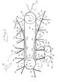
- Fig. 6
- shows a schematic side view of a folder opener that engages with a folder tail.
- Fig. 7
- shows a schematic section view taken along the line VII-VII in Fig. 6.
- Fig. 8
- shows a view corresponding to Fig. 7 when the wedge of the opener has been driven into the folder tail.
- Fig. 9
- illustrates a schematic section taken along the line IX-IX in Fig. 7.
- Fig. 10
- illustrates a schematic view taken along the line X-X in Fig. 8.
- Fig. 11
- shows a planar view of the wedge and arms of the opener.
- Fig. 12
- shows a view taken along the line XII-XII in Fig. 11.
- Fig. 13
- shows a side view taken along XIII-XIII in Fig. 11.
- The device according to Figs. 1-4 corresponds substantially to the one according to Figs. 1-4 in
SE-C-464757 additional conveyor 90 that carries openers according to the invention for folders transported in the insertion apparatus. Aconveyor 90 is also shown in connection with the apparatus illustrated in Fig. 5. - Fig. 1 schematically illustrates an
endless conveyor 10 comprising achain 11 that runs over twochain wheels conveyor 10 contains two equal parts displaced in the axial direction of thewheels pockets 14 that mouth outward away from thechain 11 and extend transverse to the longitudinal direction of thechain 11. Eachpocket 14 consists of a leadingwall 21 and atrailing wall 22, and aclip 23 at the outer end of thefront wall 21. Anendless conveyor 40 hascontrollable grippers 45 at a mutual distance, corresponding to the distance betweenadjacent pockets 14 of thechain 10. Thetransportation chain 40 is guided by a shown guide, so that thegrippers 45 run along and close by the path of thechain 11 along a part of the running path thereof such as is shown. Eachgripper 45 carries the back of afolder 20 and converges toward thechain 11 so that each folder is lifted into an appurtenant pocket. Correspondingly, theconveyor 40 and thegrippers 45 may leave the pockets by the fact that theconveyor chain 40 diverges from theconveyor 10. While the pockets are turned substantially over the horizontal plane, thegrippers 45 can be opened. Asupplement 61 can be fed out from astorage 60 and be introduced into an opened folder in a pocket that is facing upward so that thegripper 45 in question can be open, whereby thesupplement 61 can be introduced up to the back of the folder and thereby reliably be retained in the folder during further transportation by means of agripper 45. Theconveyor 45 may be a conveyor that picks up the folders (newspapers) from a printing press or the corresponding production area. - Fig. 5 shows an embodiment where the grippers 45' are fixedly attached on the
conveyor 10 at the bottom area of the pockets. In this case,folders 20 are fed down into passing pockets by means of a feeding-indevice 200. Furthermore, two feeding-indevices device 70 is illustrated that after the opening of theclip 23 closes the folder including supplements and puts the folder in a predetermined position, for instance, so that it abuts against the trailing wall of the pocket. In this way, an unloadingconveyor 80 havinggrippers 83 can work synchronously with theconveyor 11 and grip the closed folders including the supplements in the tail for transportation away. - In Figs. 1 and 5, it can be assumed, as an example, that the pockets, as facing downward, have, for instance, the
front walls 21 thereof situated approximately in the vertical plane, so that the unopened folder tends to lie next to thiswall 21. It can be seen that anendless conveyor 90 carriesopeners 91, which have a mutual distance corresponding to the pitch between thepockets 14, theconveyor 90 being synchronized with theconveyor 11 so that anopener 91 is placed close by the outer end of thefront wall 21 of eachpocket 14 and synchronously accompanies the same a chosen distance. Figs. 2-4 illustrate that theconveyor 11 may contain two mutuallyequal conveyor parts 14a and 14b, wherein thegrippers 45 may run between saidparts 14a, 14b. In Fig. 3, it can be seen that the gripper comprises asupport chute bottom line 49 of which corresponds to the bottom line of thepockets 14. Theclips 45 further comprise amovable clamping jaw 48, which co-operates with astationary clamping jaw 47 that is shown to be a wall in the support pocket. Possibly, the walls of the pockets may be mounted aroundspindles 49 at the bottom of the pocket, and furthermore, the walls of the pockets may be provided withdrivers walls - The opener conveyor may be assumed to be located between the
conveyor parts 10a, 10b, such as is illustrated. Fig. 6 schematically illustrates anopener 91 of theconveyor 90. In Fig. 6, thetail end 24 of afolder 20 can be seen. Thefolder 20 abuts against thefront pocket wall 21, which lies in theplane 26 indicated. Theopener 91 comprises abody 92, which is fitted into thetransportation chain 90. Via a pivot mounting 109, thebody 92 carries anarm 110, which at one end is provided with asupport plate 111 and which has atracer 112, for instance, a tracer roller that is guided by a guiding path, so that thesupport plate 111 can be put under in order to allow thefolder tail 24 to come into and out of the position shown without being blocked by theplate 111. Furthermore, theplate 111 should assume an exact end position, which is shown in Fig. 6 and which preferably lies in the vicinity of theplane 26. In addition, thebody 92 carries via a pivot mounting 119 anarm 120, which is turnable into and out of the shown position. Thearm 120 is shown to carry aclamping jaw 121, which is connected to thearm 120 via a pivot mounting 122. Aspring 123 resting against thearm 120 biases the clampingjaw 121 into an outer end position. The pivot mounting 122 and thespring 123 allow theclamping jaw 121 to assume end positions at different distances from thesupport plate 111 when thearms - The
arm 120 may be turned around the mounting 119 into a folded-away position to allow thefolder tail 24 to be easier introducable into the shown position in relation to thebody 92. - The
arm 120 is shown to have atracer 124, for instance, in the form of a roller, which is guided by an appurtenant guiding path, not shown in more detail, which is formed to bring about the different turning positions of thearm 120 during transportation. - The
arm 120 of the opener and possibly also thearm 110 can be turned away to allow the opener to diverge away from the path of motion of the pockets, without mutual interference. The free folder part 20b comes into abutment against the tailingfolder wall 22 and turns up toward the horizontal plane, i.e., at the left end of the conveyor according to, for instance, Fig. 5. A clip at the outer edge of therear pocket wall 22 can then clamp the tail end of the folder part 20b in a known manner per se, if it is desirable to hold both end edges of the folder parts 20a, 20b retained at the pocket walls during an insertion operation. - In, for instance, Fig. 5, it can be seen that the
conveyor 90 comprises anendless chain 92 that runs around twochain wheels 93, at least one of which is driven. One run of the chain extends along the path of motion of the free edges of downwardly turned pockets, and the pitch between theopeners 91 corresponds to the pitch between thepockets 14. - Furthermore, the
body 92 is shown to have aguide 130 for abar 131, which thereby is movable in a direction parallel to the support surface of thesupport plate 111 and thereby parallel to the main surface of the folder. Thebar 131 is, at one end thereof, provided with awedge 132, having a leadinglip 134. Thelip 134 is preferably parallel to the support surface of thesupport plate 111 and essentially perpendicular to the linear direction of motion of thebar 131. The front surface of the wedge that is facing thesupport plate 111 is preferably parallel to the support surface of the support plate. Thebar 131 is shown to have atracer 139, in the form of a roller that is guided by a guiding path (not shown) along the path of motion of the opener and the pocket, whereby thebar 131 is imparted a chosen reciprocating motion by which thewedge 132 is driven into thefolder tail 24. In this way, thewedge 132 initiates an opening of the folder tail. By adjusting the distance along the chain of theconveyor 90 between thesupport plate 111 and thewedge 132, it is possible to exactly select the position for the penetration of the wedge into the folder tail, i.e., between which pages the folder should be split. Thewedge 132 penetrates into the folder tail between thesupport plate 111 and the spring-loadedclamping plate 121. In Fig. 9, it can be seen that the clampingjaw 121 holds together the folder tail also when thewedge 132 with the shank thereof connecting thereto is driven into the folder tail. - In Figs. 11, 12,13, it can be understood that the
wedge 132 has atip 138 that is thin and has a lip that is parallel to the extension plane of the folder. The wedge has furthermore twoarms 136 that extend toward opposite directions from the tip part, and away from the plane defined by thewall 21. Thearms 136 have, on the upper sides thereof facing the folder tail, aguide edge 137 each. Said guide edges extend from thetip 138 and are substantially symmetrically diverging out of the plane of thewall 21 and away from the tip and the wedge-drivingshank 131 that is shown to extend in the displacement direction of the wedge. Thewedge 132 is shown to be carried by ashank 131 that lies in a symmetry plane to the wedge, and the guide edges 137 are accordingly mirror-symmetrical in relation to said plane. By the fact that thearms 136, in the portions thereof closest to theshank 131, extend substantially in the plane of the folder and not until at a relatively great distance from theshank 137 have portions that extend transverse to the plane of the folder, the upperfolder tail part 24A will be carried at a relatively great distance from thetip 138. The guide edges 137 try to roll up the outer folder tail part when the guide edges reach a level above the folder tail as viewed in Fig. 7, and since the effective parts of the guide edges 137 are at a relatively great distance from each other, a stable bending-up of theouter folder part 24B can be attained, which allows thegrippers 123 to be driven into engagement with the subjacentfolder tail part 24B. By the fact that the clampingjaw 121 and thesupport 111 hold together the folder tail all the way to the lower edge thereof, also when the central part of thewedge 132 is introduced in the intermediate folder tail part, the bent-up outerfolder tail parts 24A will assume the shape of triangular tongues, such as is shown in Fig. 8. In this way, the upturned outerfolder tail parts 24A are further stabilized. Possibly one may, such as is schematically illustrated at 144 in Fig. 8, temporary press supporting shoulders against the free main surface of the folder in the area above the bent-outfolder tail part 24A and so that the same experiences an additional stabilization during the period of time when thegripper 23 should be pressed. As soon as thegrippers 23 have gripped thefolder tail parts 24B, thewedge 132 can be retracted and the opener has fulfilled the work thereof. In Fig. 13, it can be seen that thewedge tip 138 has a small width and asharp lip 134 extending parallel to the extension plane of the folder, the side of the wedge tip facing thewall 21 being parallel to the same while thecorresponding surface 135 of the wedge tip converges in relation to thesurface 133 toward thelip 134.
Claims (8)
- A device for opening folders during transportation, comprising a folder conveyor (11, 12, 13) that has an endless chain having folder pockets (14) that are arranged at a mutual distance and have a wall (21) each running ahead in the direction of transportation and, at a free edge situated at the folder tail, having at least one gripper (23) for clamping a tail portion (24) of an adjacent folder part (24B) against the pocket wall (21), an opener (91) being arranged to run together with the pocket along at least a part of the path of motion thereof and the opener comprising a clamping jaw (121) arranged to clamp the folder against a support (111), and a wedge (132) that has a tip and that is displaceable for introducing the tip (138) into an edge of the folder at a selected distance from the support, characterized in that the opener (91) is arranged to run along the transversally central area of the folder tail, that the support (111) is carried by the opener, and that the wedge has two support edges (137) that diverge from the wedge tip (38) in a direction opposite the drive-in direction of the wedge in the folder, away from each other in the plane of the folder, as well as away from the support (111), so that an outer folder part (24A) deflected upon the driving-in of the wedge is supported by the two wedge support edges (137) separated along the folder tail and exposes a subjacent inner folder part (24B) so that the gripper (23) on the leading pocket wall can fix the non-deflected folder part against the pocket wall.
- Device according to claim 1, characterized in that the clamping jaw (121) of the opener (91) is spring-loaded toward the support in order to hold together the folder tail in the transversally central area where the wedge tip (132) is driven-in, and where the wedge has a small thickness in the thickness direction of the folder.
- Device according to claim 2, characterized in that the wedge (132) is arranged to be driven-in into such a depth in the folder that the two support edges thereof support the deflected outer folder part (24A) in separated positions along the folder tail and in the area over the folder main surface, at a distance from the folder edge, while the clamping jaw holds the folder compressed at the folder-tail edge, so that the deflected outer folder part (24A) forms two triangular areas, the tops of which meet at the folder-tail edge.
- Device according to any one of claims 1-3, characterized in that the pocket wall carries two grippers (23) that are separated along the free edge of the pocket wall.
- Device according to any one of claims 1-4, characterized in that the support (111) is turnably arranged on the body (92) into and out of the support position thereof.
- Device according to any one of claims 1-5, characterized in that the clamping jaw (121) is pivotally mounted (122) and spring-supported on an arm (120), which is pivotally mounted (119) on the body (92) into and out of an end position in which the clamping jaw (121) can assume different spring-loaded turning positions in relation to the arm (120).
- Device according to any one of claims 1-6, characterized in that the arm (110) carrying the support plate (111), the wedge (132) and the arm (120) carrying the clamping jaw (121) each has a tracer (112, 137, 122) that co-operates with the appurtenant guiding path for guiding their motions in relation to the body (92) along a path of motion of the body (92).
- Device according to any one of claims 1-7, characterized in that at least one opener (91) is carried by an endless conveyor (90), which brings the opener to run together with a running pocket (14) in order to, during the transportation of a folder therein, open the folder.
Applications Claiming Priority (1)
| Application Number | Priority Date | Filing Date | Title |
|---|---|---|---|
| SE0602141A SE530398C2 (en) | 2006-10-06 | 2006-10-06 | Device for opening leaflets during transport |
Publications (2)
| Publication Number | Publication Date |
|---|---|
| EP1908714A1 true EP1908714A1 (en) | 2008-04-09 |
| EP1908714B1 EP1908714B1 (en) | 2010-04-07 |
Family
ID=39032330
Family Applications (1)
| Application Number | Title | Priority Date | Filing Date |
|---|---|---|---|
| EP07445035A Not-in-force EP1908714B1 (en) | 2006-10-06 | 2007-09-27 | A device for opening folded sheets during transportation |
Country Status (7)
| Country | Link |
|---|---|
| EP (1) | EP1908714B1 (en) |
| CN (1) | CN101164852B (en) |
| AT (1) | ATE463457T1 (en) |
| DE (1) | DE602007005745D1 (en) |
| DK (1) | DK1908714T3 (en) |
| ES (1) | ES2342623T3 (en) |
| SE (1) | SE530398C2 (en) |
Cited By (1)
| Publication number | Priority date | Publication date | Assignee | Title |
|---|---|---|---|---|
| US8376123B2 (en) | 2010-05-31 | 2013-02-19 | Ferag Ag | Device and method for opening printed products |
Families Citing this family (3)
| Publication number | Priority date | Publication date | Assignee | Title |
|---|---|---|---|---|
| BRPI0913947B1 (en) * | 2008-05-26 | 2019-07-02 | Ferag Ag | APPLIANCE FOR, AND METHOD OF, INSERT FLAT ITEMS WITHIN A FOLD PRINTED PRODUCT |
| CH706457A1 (en) * | 2012-04-30 | 2013-10-31 | Ferag Ag | Method and apparatus for the insertion of objects into folded printed products. |
| CN103625148B (en) * | 2012-08-29 | 2017-01-11 | 广州市奇先印刷设备有限公司 | Full-automatic inserting device |
Citations (5)
| Publication number | Priority date | Publication date | Assignee | Title |
|---|---|---|---|---|
| DE1436585A1 (en) | 1965-12-15 | 1968-10-31 | Graphicart Int | Method and device for opening folded newspapers or the like. |
| US3450400A (en) | 1965-10-20 | 1969-06-17 | Graphicart Int | Method of and apparatus for stuffing printed matter with inserts,particularly for stuffing newspapers and the like |
| WO1991004934A1 (en) * | 1989-10-06 | 1991-04-18 | Wamac Ab | Insertion of supplements into newspapers |
| EP0596581A2 (en) | 1990-08-27 | 1994-05-11 | Graphic Management Associates, Inc. | Opener for folded printed products |
| US20040061271A1 (en) | 2001-01-19 | 2004-04-01 | Willy Leu | Device for processing printing products |
Family Cites Families (1)
| Publication number | Priority date | Publication date | Assignee | Title |
|---|---|---|---|---|
| GB9719948D0 (en) * | 1997-09-19 | 1997-11-19 | Mead Corp | Carton erecting mechanism |
-
2006
- 2006-10-06 SE SE0602141A patent/SE530398C2/en unknown
-
2007
- 2007-09-27 AT AT07445035T patent/ATE463457T1/en not_active IP Right Cessation
- 2007-09-27 ES ES07445035T patent/ES2342623T3/en active Active
- 2007-09-27 EP EP07445035A patent/EP1908714B1/en not_active Not-in-force
- 2007-09-27 DK DK07445035.4T patent/DK1908714T3/en active
- 2007-09-27 DE DE602007005745T patent/DE602007005745D1/en active Active
- 2007-10-08 CN CN200710162212XA patent/CN101164852B/en not_active Expired - Fee Related
Patent Citations (5)
| Publication number | Priority date | Publication date | Assignee | Title |
|---|---|---|---|---|
| US3450400A (en) | 1965-10-20 | 1969-06-17 | Graphicart Int | Method of and apparatus for stuffing printed matter with inserts,particularly for stuffing newspapers and the like |
| DE1436585A1 (en) | 1965-12-15 | 1968-10-31 | Graphicart Int | Method and device for opening folded newspapers or the like. |
| WO1991004934A1 (en) * | 1989-10-06 | 1991-04-18 | Wamac Ab | Insertion of supplements into newspapers |
| EP0596581A2 (en) | 1990-08-27 | 1994-05-11 | Graphic Management Associates, Inc. | Opener for folded printed products |
| US20040061271A1 (en) | 2001-01-19 | 2004-04-01 | Willy Leu | Device for processing printing products |
Cited By (1)
| Publication number | Priority date | Publication date | Assignee | Title |
|---|---|---|---|---|
| US8376123B2 (en) | 2010-05-31 | 2013-02-19 | Ferag Ag | Device and method for opening printed products |
Also Published As
| Publication number | Publication date |
|---|---|
| ES2342623T3 (en) | 2010-07-09 |
| EP1908714B1 (en) | 2010-04-07 |
| CN101164852B (en) | 2012-10-31 |
| SE530398C2 (en) | 2008-05-20 |
| ATE463457T1 (en) | 2010-04-15 |
| DK1908714T3 (en) | 2010-07-12 |
| SE0602141L (en) | 2008-04-07 |
| DE602007005745D1 (en) | 2010-05-20 |
| CN101164852A (en) | 2008-04-23 |
Similar Documents
| Publication | Publication Date | Title |
|---|---|---|
| US8556252B2 (en) | Device and method to supply print products to a processing section | |
| US5269504A (en) | Insertion of supplements into newspapers | |
| JPH06102497B2 (en) | Method and device for opening folded prints from the outside | |
| US7475522B2 (en) | Envelope filling machine | |
| EP1908714B1 (en) | A device for opening folded sheets during transportation | |
| US5474286A (en) | Process and device for opening folded printed products | |
| US3690476A (en) | Apparatus for feeding lifts of sheets without marking same | |
| FI104550B (en) | Inserting attachments in a newspaper | |
| JPH06255882A (en) | Method and device for unfolding folded print | |
| US4249841A (en) | Wire picking from a wire bundle | |
| US7621516B2 (en) | Method and apparatus for feeding flat printed products | |
| DE102007042376B4 (en) | Set up for guiding arches made of rigid material | |
| DE4314631C1 (en) | Insert loader for packaging machine - has inserts fed to collection holder by two belt drives and transferred by endless feed grips | |
| HK1115110A (en) | A device for opening folders during transportation | |
| US20060101787A1 (en) | Device for closing bags | |
| DE102004053737A1 (en) | Method and device for inserting and / or inserting pressure supplements into main printed products | |
| EP2241451B1 (en) | Envelope filling machine | |
| CA2527101C (en) | Method and apparatus for feeding flat printed products | |
| US6877732B2 (en) | Feed conveyor with opening apparatus | |
| ITTO20090300A1 (en) | DEVICE FOR FEEDING SHEETS. | |
| DE1207335B (en) | Device for placing folded and opened sheet layers on a conveyor | |
| SE531112C2 (en) | Method and apparatus for removing a group of surface widespread articles from a stack of such groups |
Legal Events
| Date | Code | Title | Description |
|---|---|---|---|
| PUAI | Public reference made under article 153(3) epc to a published international application that has entered the european phase |
Free format text: ORIGINAL CODE: 0009012 |
|
| 17P | Request for examination filed |
Effective date: 20071001 |
|
| AK | Designated contracting states |
Kind code of ref document: A1 Designated state(s): AT BE BG CH CY CZ DE DK EE ES FI FR GB GR HU IE IS IT LI LT LU LV MC MT NL PL PT RO SE SI SK TR |
|
| AX | Request for extension of the european patent |
Extension state: AL BA HR MK RS |
|
| AKX | Designation fees paid |
Designated state(s): AT BE BG CH CY CZ DE DK EE ES FI FR GB GR HU IE IS IT LI LT LU LV MC MT NL PL PT RO SE SI SK TR |
|
| 17Q | First examination report despatched |
Effective date: 20081230 |
|
| GRAP | Despatch of communication of intention to grant a patent |
Free format text: ORIGINAL CODE: EPIDOSNIGR1 |
|
| GRAS | Grant fee paid |
Free format text: ORIGINAL CODE: EPIDOSNIGR3 |
|
| GRAA | (expected) grant |
Free format text: ORIGINAL CODE: 0009210 |
|
| AK | Designated contracting states |
Kind code of ref document: B1 Designated state(s): AT BE BG CH CY CZ DE DK EE ES FI FR GB GR HU IE IS IT LI LT LU LV MC MT NL PL PT RO SE SI SK TR |
|
| REG | Reference to a national code |
Ref country code: GB Ref legal event code: FG4D |
|
| REG | Reference to a national code |
Ref country code: CH Ref legal event code: EP |
|
| REG | Reference to a national code |
Ref country code: IE Ref legal event code: FG4D |
|
| REG | Reference to a national code |
Ref country code: CH Ref legal event code: NV Representative=s name: FIAMMENGHI-FIAMMENGHI |
|
| REF | Corresponds to: |
Ref document number: 602007005745 Country of ref document: DE Date of ref document: 20100520 Kind code of ref document: P |
|
| REG | Reference to a national code |
Ref country code: NL Ref legal event code: T3 |
|
| REG | Reference to a national code |
Ref country code: ES Ref legal event code: FG2A Ref document number: 2342623 Country of ref document: ES Kind code of ref document: T3 |
|
| REG | Reference to a national code |
Ref country code: DK Ref legal event code: T3 |
|
| REG | Reference to a national code |
Ref country code: SE Ref legal event code: TRGR |
|
| PG25 | Lapsed in a contracting state [announced via postgrant information from national office to epo] |
Ref country code: SI Free format text: LAPSE BECAUSE OF FAILURE TO SUBMIT A TRANSLATION OF THE DESCRIPTION OR TO PAY THE FEE WITHIN THE PRESCRIBED TIME-LIMIT Effective date: 20100407 |
|
| LTIE | Lt: invalidation of european patent or patent extension |
Effective date: 20100407 |
|
| PG25 | Lapsed in a contracting state [announced via postgrant information from national office to epo] |
Ref country code: LT Free format text: LAPSE BECAUSE OF FAILURE TO SUBMIT A TRANSLATION OF THE DESCRIPTION OR TO PAY THE FEE WITHIN THE PRESCRIBED TIME-LIMIT Effective date: 20100407 |
|
| PG25 | Lapsed in a contracting state [announced via postgrant information from national office to epo] |
Ref country code: LV Free format text: LAPSE BECAUSE OF FAILURE TO SUBMIT A TRANSLATION OF THE DESCRIPTION OR TO PAY THE FEE WITHIN THE PRESCRIBED TIME-LIMIT Effective date: 20100407 Ref country code: IS Free format text: LAPSE BECAUSE OF FAILURE TO SUBMIT A TRANSLATION OF THE DESCRIPTION OR TO PAY THE FEE WITHIN THE PRESCRIBED TIME-LIMIT Effective date: 20100807 Ref country code: AT Free format text: LAPSE BECAUSE OF FAILURE TO SUBMIT A TRANSLATION OF THE DESCRIPTION OR TO PAY THE FEE WITHIN THE PRESCRIBED TIME-LIMIT Effective date: 20100407 |
|
| PG25 | Lapsed in a contracting state [announced via postgrant information from national office to epo] |
Ref country code: PL Free format text: LAPSE BECAUSE OF FAILURE TO SUBMIT A TRANSLATION OF THE DESCRIPTION OR TO PAY THE FEE WITHIN THE PRESCRIBED TIME-LIMIT Effective date: 20100407 Ref country code: CY Free format text: LAPSE BECAUSE OF FAILURE TO SUBMIT A TRANSLATION OF THE DESCRIPTION OR TO PAY THE FEE WITHIN THE PRESCRIBED TIME-LIMIT Effective date: 20100526 |
|
| PG25 | Lapsed in a contracting state [announced via postgrant information from national office to epo] |
Ref country code: PT Free format text: LAPSE BECAUSE OF FAILURE TO SUBMIT A TRANSLATION OF THE DESCRIPTION OR TO PAY THE FEE WITHIN THE PRESCRIBED TIME-LIMIT Effective date: 20100809 Ref country code: EE Free format text: LAPSE BECAUSE OF FAILURE TO SUBMIT A TRANSLATION OF THE DESCRIPTION OR TO PAY THE FEE WITHIN THE PRESCRIBED TIME-LIMIT Effective date: 20100407 |
|
| PLBE | No opposition filed within time limit |
Free format text: ORIGINAL CODE: 0009261 |
|
| STAA | Information on the status of an ep patent application or granted ep patent |
Free format text: STATUS: NO OPPOSITION FILED WITHIN TIME LIMIT |
|
| PG25 | Lapsed in a contracting state [announced via postgrant information from national office to epo] |
Ref country code: CZ Free format text: LAPSE BECAUSE OF FAILURE TO SUBMIT A TRANSLATION OF THE DESCRIPTION OR TO PAY THE FEE WITHIN THE PRESCRIBED TIME-LIMIT Effective date: 20100407 Ref country code: RO Free format text: LAPSE BECAUSE OF FAILURE TO SUBMIT A TRANSLATION OF THE DESCRIPTION OR TO PAY THE FEE WITHIN THE PRESCRIBED TIME-LIMIT Effective date: 20100407 Ref country code: SK Free format text: LAPSE BECAUSE OF FAILURE TO SUBMIT A TRANSLATION OF THE DESCRIPTION OR TO PAY THE FEE WITHIN THE PRESCRIBED TIME-LIMIT Effective date: 20100407 Ref country code: BE Free format text: LAPSE BECAUSE OF FAILURE TO SUBMIT A TRANSLATION OF THE DESCRIPTION OR TO PAY THE FEE WITHIN THE PRESCRIBED TIME-LIMIT Effective date: 20100407 |
|
| 26N | No opposition filed |
Effective date: 20110110 |
|
| PG25 | Lapsed in a contracting state [announced via postgrant information from national office to epo] |
Ref country code: MC Free format text: LAPSE BECAUSE OF NON-PAYMENT OF DUE FEES Effective date: 20100930 |
|
| PG25 | Lapsed in a contracting state [announced via postgrant information from national office to epo] |
Ref country code: GR Free format text: LAPSE BECAUSE OF FAILURE TO SUBMIT A TRANSLATION OF THE DESCRIPTION OR TO PAY THE FEE WITHIN THE PRESCRIBED TIME-LIMIT Effective date: 20100708 |
|
| PG25 | Lapsed in a contracting state [announced via postgrant information from national office to epo] |
Ref country code: IE Free format text: LAPSE BECAUSE OF NON-PAYMENT OF DUE FEES Effective date: 20100927 |
|
| PG25 | Lapsed in a contracting state [announced via postgrant information from national office to epo] |
Ref country code: MT Free format text: LAPSE BECAUSE OF FAILURE TO SUBMIT A TRANSLATION OF THE DESCRIPTION OR TO PAY THE FEE WITHIN THE PRESCRIBED TIME-LIMIT Effective date: 20100407 |
|
| PG25 | Lapsed in a contracting state [announced via postgrant information from national office to epo] |
Ref country code: HU Free format text: LAPSE BECAUSE OF FAILURE TO SUBMIT A TRANSLATION OF THE DESCRIPTION OR TO PAY THE FEE WITHIN THE PRESCRIBED TIME-LIMIT Effective date: 20101008 Ref country code: BG Free format text: LAPSE BECAUSE OF FAILURE TO SUBMIT A TRANSLATION OF THE DESCRIPTION OR TO PAY THE FEE WITHIN THE PRESCRIBED TIME-LIMIT Effective date: 20100407 Ref country code: LU Free format text: LAPSE BECAUSE OF NON-PAYMENT OF DUE FEES Effective date: 20100927 |
|
| PG25 | Lapsed in a contracting state [announced via postgrant information from national office to epo] |
Ref country code: TR Free format text: LAPSE BECAUSE OF FAILURE TO SUBMIT A TRANSLATION OF THE DESCRIPTION OR TO PAY THE FEE WITHIN THE PRESCRIBED TIME-LIMIT Effective date: 20100407 |
|
| PG25 | Lapsed in a contracting state [announced via postgrant information from national office to epo] |
Ref country code: BG Free format text: LAPSE BECAUSE OF FAILURE TO SUBMIT A TRANSLATION OF THE DESCRIPTION OR TO PAY THE FEE WITHIN THE PRESCRIBED TIME-LIMIT Effective date: 20100707 |
|
| REG | Reference to a national code |
Ref country code: FR Ref legal event code: PLFP Year of fee payment: 9 |
|
| PGFP | Annual fee paid to national office [announced via postgrant information from national office to epo] |
Ref country code: ES Payment date: 20150928 Year of fee payment: 9 Ref country code: GB Payment date: 20150928 Year of fee payment: 9 Ref country code: FI Payment date: 20150929 Year of fee payment: 9 |
|
| PGFP | Annual fee paid to national office [announced via postgrant information from national office to epo] |
Ref country code: FR Payment date: 20150917 Year of fee payment: 9 Ref country code: SE Payment date: 20150929 Year of fee payment: 9 |
|
| PGFP | Annual fee paid to national office [announced via postgrant information from national office to epo] |
Ref country code: DK Payment date: 20150928 Year of fee payment: 9 Ref country code: IT Payment date: 20150923 Year of fee payment: 9 |
|
| PGFP | Annual fee paid to national office [announced via postgrant information from national office to epo] |
Ref country code: DE Payment date: 20150929 Year of fee payment: 9 |
|
| PGFP | Annual fee paid to national office [announced via postgrant information from national office to epo] |
Ref country code: NL Payment date: 20150926 Year of fee payment: 9 |
|
| REG | Reference to a national code |
Ref country code: DE Ref legal event code: R119 Ref document number: 602007005745 Country of ref document: DE |
|
| REG | Reference to a national code |
Ref country code: DK Ref legal event code: EBP Effective date: 20160930 |
|
| PG25 | Lapsed in a contracting state [announced via postgrant information from national office to epo] |
Ref country code: FI Free format text: LAPSE BECAUSE OF NON-PAYMENT OF DUE FEES Effective date: 20160927 Ref country code: SE Free format text: LAPSE BECAUSE OF NON-PAYMENT OF DUE FEES Effective date: 20160928 |
|
| REG | Reference to a national code |
Ref country code: SE Ref legal event code: EUG |
|
| REG | Reference to a national code |
Ref country code: NL Ref legal event code: MM Effective date: 20161001 |
|
| GBPC | Gb: european patent ceased through non-payment of renewal fee |
Effective date: 20160927 |
|
| PG25 | Lapsed in a contracting state [announced via postgrant information from national office to epo] |
Ref country code: NL Free format text: LAPSE BECAUSE OF NON-PAYMENT OF DUE FEES Effective date: 20161001 |
|
| REG | Reference to a national code |
Ref country code: FR Ref legal event code: ST Effective date: 20170531 |
|
| PG25 | Lapsed in a contracting state [announced via postgrant information from national office to epo] |
Ref country code: FR Free format text: LAPSE BECAUSE OF NON-PAYMENT OF DUE FEES Effective date: 20160930 Ref country code: GB Free format text: LAPSE BECAUSE OF NON-PAYMENT OF DUE FEES Effective date: 20160927 Ref country code: DE Free format text: LAPSE BECAUSE OF NON-PAYMENT OF DUE FEES Effective date: 20170401 |
|
| PG25 | Lapsed in a contracting state [announced via postgrant information from national office to epo] |
Ref country code: IT Free format text: LAPSE BECAUSE OF NON-PAYMENT OF DUE FEES Effective date: 20160927 |
|
| PG25 | Lapsed in a contracting state [announced via postgrant information from national office to epo] |
Ref country code: DK Free format text: LAPSE BECAUSE OF NON-PAYMENT OF DUE FEES Effective date: 20160930 |
|
| PG25 | Lapsed in a contracting state [announced via postgrant information from national office to epo] |
Ref country code: ES Free format text: LAPSE BECAUSE OF NON-PAYMENT OF DUE FEES Effective date: 20160928 |
|
| REG | Reference to a national code |
Ref country code: ES Ref legal event code: FD2A Effective date: 20180626 |
|
| PGFP | Annual fee paid to national office [announced via postgrant information from national office to epo] |
Ref country code: CH Payment date: 20181002 Year of fee payment: 12 |
|
| REG | Reference to a national code |
Ref country code: CH Ref legal event code: PL |
|
| PG25 | Lapsed in a contracting state [announced via postgrant information from national office to epo] |
Ref country code: CH Free format text: LAPSE BECAUSE OF NON-PAYMENT OF DUE FEES Effective date: 20190930 Ref country code: LI Free format text: LAPSE BECAUSE OF NON-PAYMENT OF DUE FEES Effective date: 20190930 |