EP1908706B1 - Capsule with reduced dripping - Google Patents
Capsule with reduced dripping Download PDFInfo
- Publication number
- EP1908706B1 EP1908706B1 EP08100488A EP08100488A EP1908706B1 EP 1908706 B1 EP1908706 B1 EP 1908706B1 EP 08100488 A EP08100488 A EP 08100488A EP 08100488 A EP08100488 A EP 08100488A EP 1908706 B1 EP1908706 B1 EP 1908706B1
- Authority
- EP
- European Patent Office
- Prior art keywords
- capsule
- beverage
- compartment
- valve means
- capsule according
- Prior art date
- Legal status (The legal status is an assumption and is not a legal conclusion. Google has not performed a legal analysis and makes no representation as to the accuracy of the status listed.)
- Active
Links
Images

Classifications
-
- B—PERFORMING OPERATIONS; TRANSPORTING
- B65—CONVEYING; PACKING; STORING; HANDLING THIN OR FILAMENTARY MATERIAL
- B65D—CONTAINERS FOR STORAGE OR TRANSPORT OF ARTICLES OR MATERIALS, e.g. BAGS, BARRELS, BOTTLES, BOXES, CANS, CARTONS, CRATES, DRUMS, JARS, TANKS, HOPPERS, FORWARDING CONTAINERS; ACCESSORIES, CLOSURES, OR FITTINGS THEREFOR; PACKAGING ELEMENTS; PACKAGES
- B65D85/00—Containers, packaging elements or packages, specially adapted for particular articles or materials
- B65D85/70—Containers, packaging elements or packages, specially adapted for particular articles or materials for materials not otherwise provided for
- B65D85/804—Disposable containers or packages with contents which are mixed, infused or dissolved in situ, i.e. without having been previously removed from the package
- B65D85/8043—Packages adapted to allow liquid to pass through the contents
- B65D85/8055—Means for influencing the liquid flow inside the package
-
- A—HUMAN NECESSITIES
- A47—FURNITURE; DOMESTIC ARTICLES OR APPLIANCES; COFFEE MILLS; SPICE MILLS; SUCTION CLEANERS IN GENERAL
- A47J—KITCHEN EQUIPMENT; COFFEE MILLS; SPICE MILLS; APPARATUS FOR MAKING BEVERAGES
- A47J31/00—Apparatus for making beverages
- A47J31/02—Coffee-making machines with removable extraction cups, to be placed on top of drinking-vessels i.e. coffee-makers with removable brewing vessels, to be placed on top of beverage containers, into which hot water is poured, e.g. cafe filter
-
- B—PERFORMING OPERATIONS; TRANSPORTING
- B65—CONVEYING; PACKING; STORING; HANDLING THIN OR FILAMENTARY MATERIAL
- B65D—CONTAINERS FOR STORAGE OR TRANSPORT OF ARTICLES OR MATERIALS, e.g. BAGS, BARRELS, BOTTLES, BOXES, CANS, CARTONS, CRATES, DRUMS, JARS, TANKS, HOPPERS, FORWARDING CONTAINERS; ACCESSORIES, CLOSURES, OR FITTINGS THEREFOR; PACKAGING ELEMENTS; PACKAGES
- B65D77/00—Packages formed by enclosing articles or materials in preformed containers, e.g. boxes, cartons, sacks or bags
-
- B—PERFORMING OPERATIONS; TRANSPORTING
- B65—CONVEYING; PACKING; STORING; HANDLING THIN OR FILAMENTARY MATERIAL
- B65D—CONTAINERS FOR STORAGE OR TRANSPORT OF ARTICLES OR MATERIALS, e.g. BAGS, BARRELS, BOTTLES, BOXES, CANS, CARTONS, CRATES, DRUMS, JARS, TANKS, HOPPERS, FORWARDING CONTAINERS; ACCESSORIES, CLOSURES, OR FITTINGS THEREFOR; PACKAGING ELEMENTS; PACKAGES
- B65D85/00—Containers, packaging elements or packages, specially adapted for particular articles or materials
- B65D85/70—Containers, packaging elements or packages, specially adapted for particular articles or materials for materials not otherwise provided for
- B65D85/804—Disposable containers or packages with contents which are mixed, infused or dissolved in situ, i.e. without having been previously removed from the package
- B65D85/8043—Packages adapted to allow liquid to pass through the contents
- B65D85/8049—Details of the inlet
-
- B—PERFORMING OPERATIONS; TRANSPORTING
- B65—CONVEYING; PACKING; STORING; HANDLING THIN OR FILAMENTARY MATERIAL
- B65D—CONTAINERS FOR STORAGE OR TRANSPORT OF ARTICLES OR MATERIALS, e.g. BAGS, BARRELS, BOTTLES, BOXES, CANS, CARTONS, CRATES, DRUMS, JARS, TANKS, HOPPERS, FORWARDING CONTAINERS; ACCESSORIES, CLOSURES, OR FITTINGS THEREFOR; PACKAGING ELEMENTS; PACKAGES
- B65D85/00—Containers, packaging elements or packages, specially adapted for particular articles or materials
- B65D85/70—Containers, packaging elements or packages, specially adapted for particular articles or materials for materials not otherwise provided for
- B65D85/804—Disposable containers or packages with contents which are mixed, infused or dissolved in situ, i.e. without having been previously removed from the package
- B65D85/8043—Packages adapted to allow liquid to pass through the contents
- B65D85/8052—Details of the outlet
Definitions
- the present invention generally relates to the field of producing beverages or other liquid comestibles (soups etc.) using an ingredient-containing capsule.
- a beverage production machine injects a liquid, such as for example water, into the interior of the ingredient-containing capsule, the water interacts with the ingredients contained in the capsule.
- a liquid such as for example water
- the result of the interaction is a beverage or a liquid comestible, which can then be obtained from the capsule.
- the invention particularly relates to the field of capsules in which, during manufacture of the capsule, the ingredients are hermetically sealed in a compartment of the capsule.
- a beverage production machine which usually has means for perforating an inlet face of the capsule, means for injecting water into the capsule and means for carrying the capsule in a defined position.
- the hermetically sealed capsule is of advantage as it avoids a premature loss of volatile substances of the ingredients during transport or storage.
- the capsule is opened both at an inlet side and at an outlet side. Although the biggest portion of the liquid introduced into the interior of the capsule will be drained from the water, there will always some residual liquid remaining in the capsule after the beverage production process.
- EP-A1-1580144 which discloses the preamble of claim 1, relates to a cartridge especially for coffee machines for extracting a beverage from a particulate substance comprising slit or orifice valve formed as a pad or disc of resilient material and which opens under the pressure of the percolation fluid.
- WO2006/021405A relates to a capsule for delivering a drink by injecting a pressurized fluid comprising a body, an injection wall, a chamber containing a bed of food substance to be extracted, means for retaining the internal pressure in the said chamber.
- the improvement consists in the provision of an injection space allowing a means of injecting fluid in the form of at least one jet of fluid to be introduced through the injection wall and in providing a means for breaking the jet of fluid and distributing the distribution of fluid at a reduced speed across the surface of the bed of substance.
- These means may adopt various forms such as that of a rigid or flexible perforated wall, or a layer of discrete elements or a spongy layer.
- Such a capsule improves the flow of liquid extract through the pressure retaining means and improves the extraction conditions.
- the invention therefore has the object to reduce the risk of residual liquids and/or solids leaving the capsule after the completion of the beverage production process.
- a capsule containing ingredients for producing a beverage or liquid comestible.
- the ingredients are housed in a compartment.
- a face of the compartment is designed for the release of beverage out of the ingredient compartment under the effect of the pressure building up inside the ingredient compartment. This pressure is typically caused by the injection of water into the ingredient compartment.
- the capsule is provided with valve means arranged for selectively blocking the flow path from said face of the ingredient compartment to a beverage outlet of the capsule, wherein the valve means are arranged to co-operate with a wall of the capsule.
- Internal perforation means can be provided for opening the lower face under the effect of the pressure inside the ingredient compartment by causing the lower face and the perforation means to engage with each other in order to perforate or otherwise open the lower face.
- “Lower face” has to be understood as the face which upon opening opens a flow path towards a beverage outlet of the capsule.
- the valve means can be designed to block the flow path in an essentially airtight fashion. This constitutes one possibility of implementing the general idea of reducing or at least inhibiting a flow of air through the capsule after the completion of the beverage production process.
- the valve means can be preferably placed downstream of the lower face. This constitutes one possibility to hinder a fluid flow (in at least one direction) between the ingredient compartment and a beverage outlet opening of the capsule.
- the valve means can be designed to open the flow path selectively, i.e. only when the pressure inside the ingredient compartment is made higher than ambient pressure or generally, as soon as the beverage production process is finished, i.e. as soon as the liquid injection into the ingredient compartment stops.
- valve means can be designed to block the flow path as soon as the pressure inside the ingredient compartment does no longer exceed the ambient pressure.
- the capsule can be provided with perforation means having the general shape of a contoured plate.
- the contours e.g. pins or pyramids, are designed to assist to the opening of an adjacent face of the ingredient compartment.
- the valve means can be arranged at the periphery of the plate. Especially the valve means can be an integral part of the plate.
- the valve means can comprise a flexible lip arranged to engage in closure the adjacent wall of the capsule and be biased in opening by effect of the pressure so as to disengage from the adjacent wall.
- a further aspect of the present invention relates to a capsule, which is designed for injecting a liquid into an n ingredient compartment through an opening in an inlet face of the capsule and for draining a beverage from a beverage outlet of the capsule.
- the capsule comprises means for auto-closing off or at least largely reducing a flow of air between the beverage outlet and the opening in the inlet face of the capsule, and vice-versa, as soon as the liquid injection into the ingredient compartment ceases.
- the invention also relates to a capsule in which the valve means are designed to be mechanically opened and closed by cooperating control means arranged outside the capsule.
- the valve means can be designed to cooperate with external control means, which can be protrusions in a capsule carrier of a beverage production machine.
- the valve means can be formed by a peripheral sealing surface of an inner contoured plate of the capsule, which is selectively disengaged from the inner wall of a body of the capsule as a result of the protrusions acting in compression to inwardly deform the outer wall of the capsule and push the plate.
- the valve means can be opened as a result of the compression exerted on the capsule and the capsule carrier when the capsule is placed on the capsule carrier and the capsule is engaged by injection means of the beverage production machine.
- a still further aspect of the present invention relates to a capsule containing ingredients for producing a beverage.
- the ingredients are housed in a compartment.
- Internal opening means can be provided for opening the lower face of the ingredient compartment by having, caused by pressure inside the ingredient compartment, the lower face act against the opening means.
- the flow path from the lower face of the ingredient compartment to a beverage outlet of the capsule can comprise a chicane section designed for breaking the speed of the beverage flowing to the beverage outlet.
- a chicane section refers to a section, which changes the flow of the beverage at least once such that the beverage flow impinges on a fixed wall, which breaks the energy of the beverage jet.
- the opening means can comprise a contoured plate including at least one perforation element arranged to engage the lower face of the compartment.
- the chicane section can be at least partially defined by a bead in the outer wall of the capsule shell and the portion of wall of the contoured plate.
- a still further aspect of the present invention relates to a capsule containing ingredients for producing a beverage.
- An inlet face of the capsule is designed for injecting a liquid under pressure through an opening provided or generated in the inlet face.
- Means are provided for automatically closing off the opening after liquid injection means are retracted from the capsule and/or as soon as the liquid injection stops.
- the inlet face of the capsule can be made from a material having self-closing characteristics ("self-healing characteristics").
- the self-closing means can be made e.g. from a resilient material. These self-closing means can be made from a silicone or elastomer material applied to the inner side and outer side of the inlet face.
- a still further aspect of the present invention relates to a capsule containing ingredients for producing a beverage.
- the ingredients are housed in a compartment.
- Internal perforation means are provided designed for opening the lower face of the ingredient compartment by having, caused by pressure inside the ingredient compartment, the lower face act against the internal perforation means.
- the flow path from the lower face of the ingredient compartment to a beverage outlet of the capsule follows essentially the inner side of the outer walls of the capsule.
- Beverage flow guiding means are provided for having the beverage leaving the beverage outlet essentially in the centre of the beverage outlet.
- the flow guiding means can be a pin arranged in the centre of the beverage outlet.
- the pin can be at least partially tapered to the outside.
- the perforation means can have the shape of a contoured plate and the flow guiding means can be integrated and protrude from the lower side of the contoured plate.
- a still further aspect of the present invention relates to a capsule containing ingredients for producing a beverage, wherein an inlet face of the capsule is provided with an integrated liquid port, which is adapted to be coupled to liquid injection means of a beverage production machine.
- the integrated liquid port can protrude from the inlet face of the capsule.
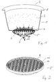
- Fig. 1 shows a capsule 1 having an ingredient compartment 3, i.e. a sealed compartment 3 which can contain beverage or liquid comestible ingredients.
- ingredient compartment 3 is hermetically sealed against the exterior.
- Attaching a foil, membrane, etc. to the upper flange-like extension 8 of the capsule walls can e.g. seal the top surface 2 in an airtight fashion.
- the upper sides 2 can be opened e.g. by perforating it with external perforation means, i.e. perforation means which are part of the beverage production machine.
- the outlet side 4 of the ingredient compartment 3 is opened by the effect of increasing the pressure inside the ingredient compartment 3 above the ambient pressure, i.e. the pressure outside the capsule 1.
- the face 4 of the ingredient compartment 3 to be opened can be made to engage with opening means which can be housed in the capsule 1 (as shown in the embodiment of Fig. 1 ) or which can be means which are external to the capsule 1.
- the lower face 4 when injecting e.g. water into the ingredient compartment 3, the lower face 4 will increasingly be engaged with the opening means until a certain threshold value is reached and the lower face 4 will open against the perforation means 5.
- the lower face 4 acts against a perforation means 5 which are integrated into the capsule 1.
- the opening means can be a contoured plate 5, such as for example a plate 5 having at the side opposing with the lower face 4 of the ingredient compartment 3, protrusion such as for example little pyramids 9.
- the shown perforation plate thus, is designed to generate a plurality of openings in the lower face 4 and a beverage being the product of the interaction of the water with the ingredients and the ingredient compartment 3 will flow through these plurality of openings into the interstices between the side walls of the pyramids 9 of the perforation plate 5.
- the perforation plate 5 preferably has no openings, such that the beverage from the ingredient compartment 3 is forced to flow towards the periphery 10 of the perforation plate 5.
- the periphery 10 of the perforation member 5 is provided with little slots 11 allowing the beverage to flow to the circumferential wall of the perforation plate 5.
- the beverage flow is schematically illustrated in Fig. 1 by little arrows.
- the liquid When the ingredient compartment 3 is pressurized, the liquid will be able to flow in a space between the perforation plate 5 and associated conical walls 6 of the capsule 1 towards a beverage outlet 7 of the capsule.
- Means can be provided for ensuring that the beverage leaves the beverage outlet 7 in a smooth manner.
- These means can e.g. be a guiding pin 14 arranged in the centre of the beverage outlet opening 7.
- the guiding pin 14 can be an integral part of the perforation plate 5 and protrudes downwards from the lower face of the perforation plate 5.
- the guiding pin 14 tapers at its lower section outwardly.
- the beverage coming from the periphery of the perforation plate 5 will be smoothly guided by the cooperation of the beverage outlet opening 7 and the guiding pin 14 and preferably leave the capsule 1 in a steady flow.
- the beverage leaving the beverage outlet opening 7 of the capsule 1 is made to directly flow into a cup or another receptacle without any additional guidance by parts of the beverage production machine. As there is no additional guidance of the beverage flow leaving the capsule 1, it has to be ensured that the beverage leaves this beverage outlet opening 7 smoothly in order to avoid the beverage splashing into the cup or another receptacle.
- the capsule 1 does not necessarily have to be arranged in a vertical orientation as indicated in Fig. 1 , but can also be arranged in any position inclined to the vertical, such as for example a horizontal position. While in the position as shown in Fig. 1 (vertical arrangement) the beverage will leave the beverage outlet 7 in a direction flushing with the rotational symmetrical axis of the capsule 1, the beverage outlet flow will describe an angle towards this symmetry axis of the capsule 1 in case the capsule 1 is arranged in a position inclined to the vertical.
- the guarding pin 14 further measures can be taken in order to promote a smooth flow of the beverage coming from the beverage ingredient compartment 3.
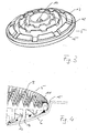
- the lower side of the perforation plate 5 can be provided with several rings 13 arranged coaxially to the centre of the perforation plate 5, in which centre the guiding pin 14 can be arranged.
- the coaxial rings 13 are respectively provided with a plurality of recessions 12, wherein recessions 12 of neighbouring rings 13 are offset relative to each other regarding their angular position when measured to the centre of the perforation plate 5.
- the areas of the rings 13 outside the recessions 12 can be made to be in full contact with the associated walls 6 of the capsule 1 or at least such that they represent a flow obstacle for the beverage stream.
- the cooperation of the offset recessions 12 with the wall 6 of the capsule 1 will force the beverage into a meandering (tortuous) path, wherein the walls defining the path break the energy of the beverage jet and promote a smooth flow towards the beverage outlet opening 7.
- the walls 6 of the capsule 1 can be provided with an outwardly extending bead 27, which also promotes a steady flow and an energy-breaking effect of the beverage jet.
- the periphery 10 of the perforation plate 5 can be provided with a flexible lip 15, which is biased against the wall 6 of the capsule.
- the lip 15 can form an acute angle with the associated wall 6 of the capsule 1.
- the beverage flow 15 will be able to push the flexible lip 15 inwards in order to open a flow path.
- the flexible lip 15 thus represents just one illustrative embodiment for having a selective valve means, which closes the flow path from the ingredient compartment 3 to the beverage outlet 7 in case the beverage ingredient compartment 3 is not pressurized. Thus, as soon as the water injection into the ingredient compartment 3 stops, the flexible lip 15 will shut off the flow path. Thus, e.g. any remaining water in the ingredient compartment 3 or on the top surface of the perforation plate can no longer exit towards the beverage outlet opening 7.
- valve means such as for example the flexible lip 15, can be made to cut-off even any airflow between the exit opening 7 and the water injection opening produced in the inlet side 2 of the capsule 1.
- This has the advantage that by at least drastically reducing the air flow through the capsule 1, the amount of liquid or solids which can leave the interior of the capsule 1 e.g. through the injection opening at the top surface 2 of the capsule can be reduced for a lack of compensating air.
- valve means are adapted to be at least an obstacle through to a flow of air and/or liquid between the beverage outlet opening 7 and the water injection opening at the top surface 2, and vice-versa.
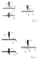
- Figures 5a-5c as well as figures 6a-6c show alternative means for prohibiting liquid and/or solids leaving an opening 18 in the top surface 2 of the capsule 1 which opening 18 is produced by introducing the water injection means 16.
- a self-healing material 17 is attached to the upper side and/or the lower side of the top surface 2.
- the water injection means 16 will go through the self-healing material 17 as well as the foil or membrane of top surface 2. Once the water injection is completed, the water injection means 16 will be retracted ( Fig. 5c ) leaving an opening 18 at the top surface 2.
- the material 17 is e.g. an elastomer, a silicone material etc. which is enable to "heal" automatically the opening made by the water injection means 16.
- Figures 6a-6c show a slightly different approach in which self-healing material forming a layer 19 is attached to the interior of the top surface. Again, both the top surface 2 material as well as the self-healing material 19 will be perforated by the perforation means 16 in order to carry out the water injection. Once the water injection and perforation means 16 are retracted ( Fig. 6c ), the expanding material 19 will heal the opening 18 left by the water injection perforation member 16.
- the expanding material 19 can e.g. be made from a super-absorbing polymer (SAP) which can take up e.g. up to 100 times of its own weight of water.
- a layer of this expanding material 19 can be installed e.g. as an inner film or by hot melting under a membrane forming the top surface 2.
- the expanding material can e.g. absorb water and then be transformed into a gel, which blocks the opening 18.
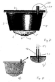
- Fig. 7 shows an embodiment of the capsule 1 which is provided with its own water injection port 20.
- the water injection port 20, being sealed via means 21 vis-à-vis the top surface 2 of the capsule 1, is part of the capsule 1 and not of the associated beverage production machine.
- a water injection port 23 can be docked in a seal fashion to the port 22 of the capsule 1.
- the water injection port 22 of the capsule 1 has a relatively small diameter in order to promote a capillarity effect.
- the inner diameter of the water injection port 22 is between some 0.1 and 0.3 mm, a capillary effect will occur which retains water inside the port 22 even after the water injection pipe 23 of the beverage production device is removed.
- the water remaining in the form of a meniscus inside the port 22 will then represent an air barrier, i.e. air ingress is avoided and the loss of residual liquid from the capsule is reduced.
- Fig. 9 shows an embodiment of a capsule 1 being an example for having external control means for controlling the valve means inside the capsule in order to stop air and/or liquid flow inside the capsule once the water injection is stopped.
- the capsule holder 24 in which the capsule 1 is inserted for use with the beverage production machine is provided with two bosses 25 which urge against the wall of the capsule 1 at a defined position 26 when the capsule 1 is inserted under thrust into the capsule carrier 24.
- the perforation plate 5 is provided with sealing means such as for example the flexible lip 15 (see for example figures 3 and 4 ). Therefore, as long as the perforation plate 5 is lifted by the engagement with the bosses 25 of the capsule carrier 24, the beverage can flow around the periphery of the perforation plate 5 and can flow to the beverage outlet opening 7 of the capsule 1. However, as soon as the thrust against the portions 26 of the capsule walls ceases, e.g. because the capsule 1 is separated from the capsule carrier 24, the perforation plate 5 will resume its initial position in which it is seated such that it shuts off the flow of air and/or liquid between the ingredient compartment 3 and the beverage outlet opening 7.
- sealing means such as for example the flexible lip 15 (see for example figures 3 and 4 ). Therefore, as long as the perforation plate 5 is lifted by the engagement with the bosses 25 of the capsule carrier 24, the beverage can flow around the periphery of the perforation plate 5 and can flow to the beverage outlet opening 7 of the capsule 1. However, as soon as the thrust against the portions 26 of the
Landscapes
- Engineering & Computer Science (AREA)
- Mechanical Engineering (AREA)
- Food Science & Technology (AREA)
- Apparatus For Making Beverages (AREA)
- Packages (AREA)
- Devices For Dispensing Beverages (AREA)
- Packging For Living Organisms, Food Or Medicinal Products That Are Sensitive To Environmental Conditiond (AREA)
- Closures For Containers (AREA)
- Pharmaceuticals Containing Other Organic And Inorganic Compounds (AREA)
- Medicinal Preparation (AREA)
Description
- The present invention generally relates to the field of producing beverages or other liquid comestibles (soups etc.) using an ingredient-containing capsule.
- When a beverage production machine injects a liquid, such as for example water, into the interior of the ingredient-containing capsule, the water interacts with the ingredients contained in the capsule. The result of the interaction is a beverage or a liquid comestible, which can then be obtained from the capsule.
- The invention particularly relates to the field of capsules in which, during manufacture of the capsule, the ingredients are hermetically sealed in a compartment of the capsule. In other words, an exposure of the ingredients to the ambience is only produced after the capsule has been inserted into a beverage production machine, which usually has means for perforating an inlet face of the capsule, means for injecting water into the capsule and means for carrying the capsule in a defined position.
- The hermetically sealed capsule is of advantage as it avoids a premature loss of volatile substances of the ingredients during transport or storage.
- At the end of the beverage production process the capsule is opened both at an inlet side and at an outlet side. Although the biggest portion of the liquid introduced into the interior of the capsule will be drained from the water, there will always some residual liquid remaining in the capsule after the beverage production process.
- Particularly when the capsule is then taken out from the beverage production machine, there is the problem of water or beverage dripping e.g. from the water inlet side of the capsule. It is thought that this dripping is particularly promoted by air entering the capsule from the beverage outlet side.
- Sometimes this problem is even aggravated when the beverage leaving the water inlet side of the capsule causes even solids such as coffee powder to leave the capsule on the water inlet side. This can lead to a cross-contamination of elements of the beverage production machine, which constitutes a particular problem when the beverage production machine is used for different beverages (e.g. coffee, tea, juice, milk ...).
-
EP-A1-1580144 , which discloses the preamble ofclaim 1, relates to a cartridge especially for coffee machines for extracting a beverage from a particulate substance comprising slit or orifice valve formed as a pad or disc of resilient material and which opens under the pressure of the percolation fluid. -
WO2006/021405A relates to a capsule for delivering a drink by injecting a pressurized fluid comprising a body, an injection wall, a chamber containing a bed of food substance to be extracted, means for retaining the internal pressure in the said chamber. The improvement consists in the provision of an injection space allowing a means of injecting fluid in the form of at least one jet of fluid to be introduced through the injection wall and in providing a means for breaking the jet of fluid and distributing the distribution of fluid at a reduced speed across the surface of the bed of substance. These means may adopt various forms such as that of a rigid or flexible perforated wall, or a layer of discrete elements or a spongy layer. Such a capsule improves the flow of liquid extract through the pressure retaining means and improves the extraction conditions. - The invention therefore has the object to reduce the risk of residual liquids and/or solids leaving the capsule after the completion of the beverage production process.
- This object is achieved by means of the features of the independent claims. The depending claims develop further the central idea of the present invention.
- According to a first aspect, a capsule is proposed containing ingredients for producing a beverage or liquid comestible. The ingredients are housed in a compartment. A face of the compartment is designed for the release of beverage out of the ingredient compartment under the effect of the pressure building up inside the ingredient compartment. This pressure is typically caused by the injection of water into the ingredient compartment. The capsule is provided with valve means arranged for selectively blocking the flow path from said face of the ingredient compartment to a beverage outlet of the capsule, wherein the valve means are arranged to co-operate with a wall of the capsule.
- Internal perforation means can be provided for opening the lower face under the effect of the pressure inside the ingredient compartment by causing the lower face and the perforation means to engage with each other in order to perforate or otherwise open the lower face. "Lower face" has to be understood as the face which upon opening opens a flow path towards a beverage outlet of the capsule.
- The valve means can be designed to block the flow path in an essentially airtight fashion. This constitutes one possibility of implementing the general idea of reducing or at least inhibiting a flow of air through the capsule after the completion of the beverage production process.
- The valve means can be preferably placed downstream of the lower face. This constitutes one possibility to hinder a fluid flow (in at least one direction) between the ingredient compartment and a beverage outlet opening of the capsule.
- The valve means can be designed to open the flow path selectively, i.e. only when the pressure inside the ingredient compartment is made higher than ambient pressure or generally, as soon as the beverage production process is finished, i.e. as soon as the liquid injection into the ingredient compartment stops.
- Correspondingly, the valve means can be designed to block the flow path as soon as the pressure inside the ingredient compartment does no longer exceed the ambient pressure.
- The capsule can be provided with perforation means having the general shape of a contoured plate. The contours, e.g. pins or pyramids, are designed to assist to the opening of an adjacent face of the ingredient compartment. The valve means can be arranged at the periphery of the plate. Especially the valve means can be an integral part of the plate.
- The valve means can comprise a flexible lip arranged to engage in closure the adjacent wall of the capsule and be biased in opening by effect of the pressure so as to disengage from the adjacent wall.
- A further aspect of the present invention relates to a capsule, which is designed for injecting a liquid into an n ingredient compartment through an opening in an inlet face of the capsule and for draining a beverage from a beverage outlet of the capsule. The capsule comprises means for auto-closing off or at least largely reducing a flow of air between the beverage outlet and the opening in the inlet face of the capsule, and vice-versa, as soon as the liquid injection into the ingredient compartment ceases.
- The invention also relates to a capsule in which the valve means are designed to be mechanically opened and closed by cooperating control means arranged outside the capsule.
- The valve means can be designed to cooperate with external control means, which can be protrusions in a capsule carrier of a beverage production machine.
- The valve means can be formed by a peripheral sealing surface of an inner contoured plate of the capsule, which is selectively disengaged from the inner wall of a body of the capsule as a result of the protrusions acting in compression to inwardly deform the outer wall of the capsule and push the plate.
- The valve means can be opened as a result of the compression exerted on the capsule and the capsule carrier when the capsule is placed on the capsule carrier and the capsule is engaged by injection means of the beverage production machine.
- A still further aspect of the present invention relates to a capsule containing ingredients for producing a beverage. The ingredients are housed in a compartment. Internal opening means can be provided for opening the lower face of the ingredient compartment by having, caused by pressure inside the ingredient compartment, the lower face act against the opening means. Thereby the flow path from the lower face of the ingredient compartment to a beverage outlet of the capsule can comprise a chicane section designed for breaking the speed of the beverage flowing to the beverage outlet. A chicane section refers to a section, which changes the flow of the beverage at least once such that the beverage flow impinges on a fixed wall, which breaks the energy of the beverage jet.
- The opening means can comprise a contoured plate including at least one perforation element arranged to engage the lower face of the compartment.
- The chicane section can be at least partially defined by a bead in the outer wall of the capsule shell and the portion of wall of the contoured plate.
- A still further aspect of the present invention relates to a capsule containing ingredients for producing a beverage. An inlet face of the capsule is designed for injecting a liquid under pressure through an opening provided or generated in the inlet face. Means are provided for automatically closing off the opening after liquid injection means are retracted from the capsule and/or as soon as the liquid injection stops.
- The inlet face of the capsule can be made from a material having self-closing characteristics ("self-healing characteristics").
- The self-closing means can be made e.g. from a resilient material. These self-closing means can be made from a silicone or elastomer material applied to the inner side and outer side of the inlet face.
- A still further aspect of the present invention relates to a capsule containing ingredients for producing a beverage. The ingredients are housed in a compartment. Internal perforation means are provided designed for opening the lower face of the ingredient compartment by having, caused by pressure inside the ingredient compartment, the lower face act against the internal perforation means. The flow path from the lower face of the ingredient compartment to a beverage outlet of the capsule follows essentially the inner side of the outer walls of the capsule. Beverage flow guiding means are provided for having the beverage leaving the beverage outlet essentially in the centre of the beverage outlet.
- The flow guiding means can be a pin arranged in the centre of the beverage outlet.
- The pin can be at least partially tapered to the outside.
- The perforation means can have the shape of a contoured plate and the flow guiding means can be integrated and protrude from the lower side of the contoured plate.
- A still further aspect of the present invention relates to a capsule containing ingredients for producing a beverage, wherein an inlet face of the capsule is provided with an integrated liquid port, which is adapted to be coupled to liquid injection means of a beverage production machine. The integrated liquid port can protrude from the inlet face of the capsule.
- Further aspects, objects and advantages of the present invention will become evident from the following description of preferred embodiments of the present invention taken in conjunction with the figures of the enclosed drawings.
- Fig. 1
- shows a cross-sectional view of a capsule according to the present invention,
- Fig. 2
- shows a view of a perforation plate according to the present invention,
- Fig. 3
- shows the lower side of the perforation plate of
Fig. 2 , - Fig. 4
- shows an enlarged view of the engagement between the perforation plate and the adjacent walls of the capsule,
- Fig. 5
- shows a first embodiment for an automatic re-closing of the inlet face of the capsule after retraction of water injection means,
- Fig. 6
- shows a second embodiment for auto-closing means of the perforation in the inlet face of the capsule,
- Fig. 7
- shows a capsule with integrated water inlet port,
- Fig. 8
- shows details of the functionality of the water inlet port of the capsule according to
Fig. 7 , and - Fig. 9
- shows a further embodiment illustrating one possibility to mechanically control valve means inside the capsule via control means placed outside the capsule.
- With reference to
Fig. 1 at first the general principle to be applied with the present invention will be explained. -
Fig. 1 shows acapsule 1 having aningredient compartment 3, i.e. a sealedcompartment 3 which can contain beverage or liquid comestible ingredients. Before the use of thecapsule 1 in an associated adapted beverage production machine, theingredient compartment 3 is hermetically sealed against the exterior. - Attaching a foil, membrane, etc. to the upper flange-like extension 8 of the capsule walls can e.g. seal the
top surface 2 in an airtight fashion. As will be explained later on in detail with reference tofigures 5 and 6 , theupper sides 2 can be opened e.g. by perforating it with external perforation means, i.e. perforation means which are part of the beverage production machine. - According to the invention, the
outlet side 4 of theingredient compartment 3 is opened by the effect of increasing the pressure inside theingredient compartment 3 above the ambient pressure, i.e. the pressure outside thecapsule 1. To this regard, theface 4 of theingredient compartment 3 to be opened can be made to engage with opening means which can be housed in the capsule 1 (as shown in the embodiment ofFig. 1 ) or which can be means which are external to thecapsule 1. - In any case, when injecting e.g. water into the
ingredient compartment 3, thelower face 4 will increasingly be engaged with the opening means until a certain threshold value is reached and thelower face 4 will open against the perforation means 5. - In the embodiment shown in
Fig. 1 , which is meant to be a non-limiting illustration only, thelower face 4 acts against a perforation means 5 which are integrated into thecapsule 1. Particularly, as can also be seen in detail inFig. 2 , the opening means can be a contoured plate 5, such as for example a plate 5 having at the side opposing with thelower face 4 of theingredient compartment 3, protrusion such as for example little pyramids 9. - Thus, when increasing the pressure inside the
ingredient compartment 3, the lower face will eventually tear against the pyramids 9 of the perforation plate 5. - The shown perforation plate, thus, is designed to generate a plurality of openings in the
lower face 4 and a beverage being the product of the interaction of the water with the ingredients and theingredient compartment 3 will flow through these plurality of openings into the interstices between the side walls of the pyramids 9 of the perforation plate 5. - The perforation plate 5 preferably has no openings, such that the beverage from the
ingredient compartment 3 is forced to flow towards theperiphery 10 of the perforation plate 5. - The
periphery 10 of the perforation member 5 is provided withlittle slots 11 allowing the beverage to flow to the circumferential wall of the perforation plate 5. - The beverage flow is schematically illustrated in
Fig. 1 by little arrows. - When the
ingredient compartment 3 is pressurized, the liquid will be able to flow in a space between the perforation plate 5 and associatedconical walls 6 of thecapsule 1 towards abeverage outlet 7 of the capsule. - Therefore, in the region of the
conical walls 6 the beverage flow essentially follows the inner side of thecapsule walls 6. - Means can be provided for ensuring that the beverage leaves the
beverage outlet 7 in a smooth manner. These means can e.g. be a guiding pin 14 arranged in the centre of thebeverage outlet opening 7. The guiding pin 14 can be an integral part of the perforation plate 5 and protrudes downwards from the lower face of the perforation plate 5. Preferably, the guiding pin 14 tapers at its lower section outwardly. - Therefore, the beverage coming from the periphery of the perforation plate 5 will be smoothly guided by the cooperation of the
beverage outlet opening 7 and the guiding pin 14 and preferably leave thecapsule 1 in a steady flow. - This is particularly of importance in case the so-called "direct-flow" principle is used. According to the direct-flow principle, the beverage leaving the beverage outlet opening 7 of the
capsule 1 is made to directly flow into a cup or another receptacle without any additional guidance by parts of the beverage production machine. As there is no additional guidance of the beverage flow leaving thecapsule 1, it has to be ensured that the beverage leaves thisbeverage outlet opening 7 smoothly in order to avoid the beverage splashing into the cup or another receptacle. - Note that according to the direct-flow principle, the
capsule 1 does not necessarily have to be arranged in a vertical orientation as indicated inFig. 1 , but can also be arranged in any position inclined to the vertical, such as for example a horizontal position. While in the position as shown inFig. 1 (vertical arrangement) the beverage will leave thebeverage outlet 7 in a direction flushing with the rotational symmetrical axis of thecapsule 1, the beverage outlet flow will describe an angle towards this symmetry axis of thecapsule 1 in case thecapsule 1 is arranged in a position inclined to the vertical. - In addition or alternatively to the guarding pin 14 further measures can be taken in order to promote a smooth flow of the beverage coming from the
beverage ingredient compartment 3. As shown inFig. 3 , the lower side of the perforation plate 5 can be provided withseveral rings 13 arranged coaxially to the centre of the perforation plate 5, in which centre the guiding pin 14 can be arranged. - The coaxial rings 13 are respectively provided with a plurality of
recessions 12, whereinrecessions 12 of neighbouringrings 13 are offset relative to each other regarding their angular position when measured to the centre of the perforation plate 5. - The areas of the
rings 13 outside therecessions 12 can be made to be in full contact with the associatedwalls 6 of thecapsule 1 or at least such that they represent a flow obstacle for the beverage stream. - In any case, as indicated in
figures 1 and4 , the cooperation of the offsetrecessions 12 with thewall 6 of thecapsule 1 will force the beverage into a meandering (tortuous) path, wherein the walls defining the path break the energy of the beverage jet and promote a smooth flow towards thebeverage outlet opening 7. - Additionally, in the area surrounding the
beverage outlet 7, thewalls 6 of thecapsule 1 can be provided with an outwardly extending bead 27, which also promotes a steady flow and an energy-breaking effect of the beverage jet. - As can be seen from
figures 3 and 4 , theperiphery 10 of the perforation plate 5 can be provided with aflexible lip 15, which is biased against thewall 6 of the capsule. When seen in the flow-direction of the beverage flow path, thelip 15 can form an acute angle with the associatedwall 6 of thecapsule 1. As long as theingredient compartment 3 is pressurized, thebeverage flow 15 will be able to push theflexible lip 15 inwards in order to open a flow path. - The
flexible lip 15 thus represents just one illustrative embodiment for having a selective valve means, which closes the flow path from theingredient compartment 3 to thebeverage outlet 7 in case thebeverage ingredient compartment 3 is not pressurized. Thus, as soon as the water injection into theingredient compartment 3 stops, theflexible lip 15 will shut off the flow path. Thus, e.g. any remaining water in theingredient compartment 3 or on the top surface of the perforation plate can no longer exit towards thebeverage outlet opening 7. - Additionally, the valve means, such as for example the
flexible lip 15, can be made to cut-off even any airflow between theexit opening 7 and the water injection opening produced in theinlet side 2 of thecapsule 1. This has the advantage that by at least drastically reducing the air flow through thecapsule 1, the amount of liquid or solids which can leave the interior of thecapsule 1 e.g. through the injection opening at thetop surface 2 of the capsule can be reduced for a lack of compensating air. - Note that many different valve arrangements and positions for the valve can be thought of, as long as the valve means are adapted to be at least an obstacle through to a flow of air and/or liquid between the
beverage outlet opening 7 and the water injection opening at thetop surface 2, and vice-versa. -
Figures 5a-5c as well asfigures 6a-6c show alternative means for prohibiting liquid and/or solids leaving anopening 18 in thetop surface 2 of thecapsule 1 whichopening 18 is produced by introducing the water injection means 16. - In the embodiment of
figure 5 a self-healingmaterial 17 is attached to the upper side and/or the lower side of thetop surface 2. As shown infigures 5a-5c , the water injection means 16 will go through the self-healingmaterial 17 as well as the foil or membrane oftop surface 2. Once the water injection is completed, the water injection means 16 will be retracted (Fig. 5c ) leaving anopening 18 at thetop surface 2. According to the invention thematerial 17 is e.g. an elastomer, a silicone material etc. which is enable to "heal" automatically the opening made by the water injection means 16. -
Figures 6a-6c show a slightly different approach in which self-healing material forming alayer 19 is attached to the interior of the top surface. Again, both thetop surface 2 material as well as the self-healingmaterial 19 will be perforated by the perforation means 16 in order to carry out the water injection. Once the water injection and perforation means 16 are retracted (Fig. 6c ), the expandingmaterial 19 will heal theopening 18 left by the waterinjection perforation member 16. The expandingmaterial 19 can e.g. be made from a super-absorbing polymer (SAP) which can take up e.g. up to 100 times of its own weight of water. A layer of this expandingmaterial 19 can be installed e.g. as an inner film or by hot melting under a membrane forming thetop surface 2. The expanding material can e.g. absorb water and then be transformed into a gel, which blocks theopening 18. -
Fig. 7 shows an embodiment of thecapsule 1 which is provided with its ownwater injection port 20. Thewater injection port 20, being sealed viameans 21 vis-à-vis thetop surface 2 of thecapsule 1, is part of thecapsule 1 and not of the associated beverage production machine. As can be seen for example fromFig. 8b , a water injection port 23 can be docked in a seal fashion to theport 22 of thecapsule 1. As can be schematically seen inFig. 8b , preferably thewater injection port 22 of thecapsule 1 has a relatively small diameter in order to promote a capillarity effect. E.g., if the inner diameter of thewater injection port 22 is between some 0.1 and 0.3 mm, a capillary effect will occur which retains water inside theport 22 even after the water injection pipe 23 of the beverage production device is removed. The water remaining in the form of a meniscus inside theport 22 will then represent an air barrier, i.e. air ingress is avoided and the loss of residual liquid from the capsule is reduced. -
Fig. 9 shows an embodiment of acapsule 1 being an example for having external control means for controlling the valve means inside the capsule in order to stop air and/or liquid flow inside the capsule once the water injection is stopped. - According to the embodiment on
Fig. 9 thecapsule holder 24 in which thecapsule 1 is inserted for use with the beverage production machine is provided with twobosses 25 which urge against the wall of thecapsule 1 at a definedposition 26 when thecapsule 1 is inserted under thrust into thecapsule carrier 24. - Thus, as long as the
capsule 1 is thrust against thebosses 25, thesebosses 25 will press theportion 26 of the capsule walls slightly inside and will thus slightly lift the perforation member 5 relative to the associate wall of thecapsule 1. - Preferably, the perforation plate 5 is provided with sealing means such as for example the flexible lip 15 (see for example
figures 3 and 4 ). Therefore, as long as the perforation plate 5 is lifted by the engagement with thebosses 25 of thecapsule carrier 24, the beverage can flow around the periphery of the perforation plate 5 and can flow to the beverage outlet opening 7 of thecapsule 1. However, as soon as the thrust against theportions 26 of the capsule walls ceases, e.g. because thecapsule 1 is separated from thecapsule carrier 24, the perforation plate 5 will resume its initial position in which it is seated such that it shuts off the flow of air and/or liquid between theingredient compartment 3 and thebeverage outlet opening 7.
Claims (10)
- A capsule containing ingredients for producing a beverage,
wherein the ingredients are housed in a compartment (3),
a face (4) of the compartment being designed for the release of beverage out of the compartment under the effect of the pressure inside the ingredient compartment (3),
the capsule being provided with valve means (15) arranged for selectively blocking the flow path from said face of the ingredient compartment to a beverage outlet of the capsule characterized in that the valve means (15) are arranged to co-operate with a wall (6) of the capsule. - The capsule according to claim 1,
wherein internal perforation means (5) are provided for opening the lower face (4) under the effect of the pressure inside the compartment by causing the lower face and perforation means (5) to engage and the lower face being perforated accordingly. - The capsule according to claim 1 or 2,
wherein the valve means (15) are designed to block the flow path in an essentially airtight fashion. - The capsule according to any of the preceding claims, wherein the valve means (15) is placed downstream of the face (4) of the compartment.
- The capsule according to any of the preceding claims,
wherein the valve means (15) are designed to open the flow path only when the pressure inside the ingredient compartment (3) is higher than ambient pressure. - The capsule according to any of the preceding claims,
wherein the perforation means (5) has the general shape of a contoured plate, and wherein the valve means (15) are arranged at the periphery of the plate. - The capsule according to claim 6,
wherein the valve means (15) is an integral part of the plate. - The capsule according to claim 7,
wherein the valve means comprise a flexible lip (15) arranged to engage in closure the adjacent wall (6) of the capsule and be biased in opening by effect of the pressure so as to disengage from the adjacent wall. - The capsule according to any of the preceding
claims, wherein the flowpath from the lower face (4) of the ingredient compartment to a beverage outlet (7) of the capsule comprises a chicane section (12, 13) designed for braking the speed of the beverage flowing to the beverage outlet. - The capsule according to any of the preceding
claims, wherein flow guiding means (14) are provided for having the beverage leaving the beverage outlet essentially in the centre of the beverage outlet.
Priority Applications (4)
| Application Number | Priority Date | Filing Date | Title |
|---|---|---|---|
| DK08100488.9T DK1908706T3 (en) | 2006-06-06 | 2006-06-06 | Capsule with reduced drip |
| PL08100488T PL1908706T3 (en) | 2006-06-06 | 2006-06-06 | Capsule with reduced dripping |
| DE602006011328T DE602006011328D1 (en) | 2006-06-06 | 2006-06-06 | Capsule with reduced dripping |
| HR20100136T HRP20100136T1 (en) | 2006-06-06 | 2010-03-10 | Capsule with reduced dripping |
Applications Claiming Priority (1)
| Application Number | Priority Date | Filing Date | Title |
|---|---|---|---|
| EP06011671A EP1864917B1 (en) | 2006-06-06 | 2006-06-06 | Capsule with reduced dripping |
Related Parent Applications (1)
| Application Number | Title | Priority Date | Filing Date |
|---|---|---|---|
| EP06011671A Division EP1864917B1 (en) | 2006-06-06 | 2006-06-06 | Capsule with reduced dripping |
Publications (3)
| Publication Number | Publication Date |
|---|---|
| EP1908706A2 EP1908706A2 (en) | 2008-04-09 |
| EP1908706A3 EP1908706A3 (en) | 2008-04-16 |
| EP1908706B1 true EP1908706B1 (en) | 2009-12-23 |
Family
ID=37144117
Family Applications (3)
| Application Number | Title | Priority Date | Filing Date |
|---|---|---|---|
| EP06011671A Active EP1864917B1 (en) | 2006-06-06 | 2006-06-06 | Capsule with reduced dripping |
| EP08100488A Active EP1908706B1 (en) | 2006-06-06 | 2006-06-06 | Capsule with reduced dripping |
| EP07729783A Active EP2029458B1 (en) | 2006-06-06 | 2007-06-01 | Capsule with reduced dripping |
Family Applications Before (1)
| Application Number | Title | Priority Date | Filing Date |
|---|---|---|---|
| EP06011671A Active EP1864917B1 (en) | 2006-06-06 | 2006-06-06 | Capsule with reduced dripping |
Family Applications After (1)
| Application Number | Title | Priority Date | Filing Date |
|---|---|---|---|
| EP07729783A Active EP2029458B1 (en) | 2006-06-06 | 2007-06-01 | Capsule with reduced dripping |
Country Status (32)
| Country | Link |
|---|---|
| US (1) | US8807018B2 (en) |
| EP (3) | EP1864917B1 (en) |
| JP (1) | JP5080571B2 (en) |
| KR (1) | KR101400596B1 (en) |
| CN (1) | CN101466618B (en) |
| AR (1) | AR062819A1 (en) |
| AT (3) | ATE452839T1 (en) |
| AU (1) | AU2007255494C1 (en) |
| BR (1) | BRPI0712900B1 (en) |
| CA (1) | CA2652575C (en) |
| CL (1) | CL2007001633A1 (en) |
| CY (1) | CY1108406T1 (en) |
| DE (3) | DE602006011328D1 (en) |
| DK (2) | DK1908706T3 (en) |
| ES (3) | ES2313501T3 (en) |
| HR (2) | HRP20080487T3 (en) |
| HU (1) | HU231060B1 (en) |
| MA (1) | MA31721B1 (en) |
| MX (1) | MX2008015563A (en) |
| MY (1) | MY148005A (en) |
| NO (1) | NO338068B1 (en) |
| NZ (1) | NZ572938A (en) |
| PE (1) | PE20080618A1 (en) |
| PL (3) | PL1908706T3 (en) |
| PT (2) | PT1864917E (en) |
| RU (1) | RU2443614C2 (en) |
| SI (2) | SI1864917T1 (en) |
| TW (1) | TWI324124B (en) |
| UA (1) | UA97955C2 (en) |
| UY (1) | UY30390A1 (en) |
| WO (1) | WO2007141202A1 (en) |
| ZA (1) | ZA200900064B (en) |
Families Citing this family (92)
| Publication number | Priority date | Publication date | Assignee | Title |
|---|---|---|---|---|
| UA96983C2 (en) * | 2007-03-23 | 2011-12-26 | Нестек С.А. | Beverage ingredient capsule |
| CN102026891B (en) * | 2008-03-10 | 2012-08-22 | 绿山咖啡烘培公司 | Beverage cartridge |
| CA2716610A1 (en) * | 2008-03-18 | 2009-09-24 | Nestec S.A. | Cartridge for preparation of a liquid comprising a puncturable delivery wall |
| IT1391803B1 (en) * | 2008-11-26 | 2012-01-27 | Brasilia Spa | DISPOSABLE CAPSULE OF CONTAINMENT OF AN AROMATIC ESSENCE FOR THE PRODUCTION OF AN INFUSION |
| AT507834B1 (en) | 2009-01-29 | 2011-03-15 | System Gmbh K | PORTION CAPSULE |
| DE202009018805U1 (en) * | 2009-06-17 | 2013-07-09 | Koninklijke Douwe Egberts B.V. | Capsule for containing beverage ingredients |
| US9527661B2 (en) | 2009-09-29 | 2016-12-27 | Lbp Manufacturing Llc | Disposable single use beverage package |
| US9108794B2 (en) | 2009-09-29 | 2015-08-18 | Lbp Manufacturing, Inc. | Disposable single use beverage package |
| US9282848B2 (en) * | 2009-11-09 | 2016-03-15 | Mds Global Holding P.L.C. | Beverage brewing devices |
| DK2506745T3 (en) * | 2009-12-01 | 2013-12-16 | Nestec Sa | CARTRIDGE-extraction device |
| BR112012029446A2 (en) * | 2010-05-19 | 2017-02-21 | Nestec Sa | beverage production system using capsules |
| GB2481068B (en) | 2010-06-11 | 2012-06-20 | Kraft Foods R & D Inc | Cartridge for the preparation of beverages |
| AU2011264420B2 (en) * | 2010-06-11 | 2015-05-28 | Breville Pty Limited | Milk frother |
| US9290343B1 (en) | 2010-06-24 | 2016-03-22 | Coffco, Llc | System for singly dispensing fibrous filters from bulk |
| US9290342B1 (en) * | 2010-06-24 | 2016-03-22 | Coffco, Llc | System for singly dispensing fibrous filters from bulk |
| EP2412646A1 (en) * | 2010-07-28 | 2012-02-01 | Nestec S.A. | A capsule for food preparation |
| AU2011301237A1 (en) * | 2010-09-15 | 2013-03-28 | Nestec S.A. | Capsule with enhanced product delivery system |
| IT1403914B1 (en) * | 2011-02-04 | 2013-11-08 | Technology For Beverage Srl | METHOD OF INTRODUCTION OF WATER INSIDE A CLOSED CAPSULE FOR THE INFUSION OF AN AROMATIC ESSENCE PUT INSIDE THE CAPSULE, CONTAINMENT CAPSULE OF AN AROMATIC ESSENCE THAT IS SUBJECT TO INFUSION, AND A PERFORATION DEVICE OF SUCH A CAPSULE |
| PT105598B (en) * | 2011-03-30 | 2020-01-17 | Novadelta Comercio E Ind De Cafes Lda | CONTROLLED OPENING CAPSULE, PROCESS AND OPERATING DEVICE OF THIS CAPSULE |
| PT105597B (en) | 2011-03-30 | 2020-04-20 | Novadelta Comercio E Ind De Cafes Lda | CAPSULE AND PROCESSING DEVICE FOR THIS CAPSULE |
| EP2520202B1 (en) * | 2011-05-02 | 2014-07-23 | Mocoffee AG | Device and capsule for preparing a beverage |
| GB2491154B (en) * | 2011-05-24 | 2013-07-10 | Kraft Foods R & D Inc | Beverage/food product preparation systems |
| USD675089S1 (en) | 2011-05-25 | 2013-01-29 | Lbp Manufacturing, Inc. | Disposable cup with curved rib |
| USD675091S1 (en) | 2011-05-25 | 2013-01-29 | Lbp Manufacturing, Inc. | Disposable cup with wave rib |
| USD675090S1 (en) | 2011-05-25 | 2013-01-29 | Lbp Manufacturing, Inc. | Disposable cup with straight rib |
| CN103687794B (en) * | 2011-07-19 | 2016-05-18 | 3M创新有限公司 | Airtight container and method of use thereof |
| US9452879B2 (en) | 2011-07-26 | 2016-09-27 | Lbp Manufacturing Llc | Sealed beverage basket and method of making |
| ES2370862B9 (en) * | 2011-08-10 | 2012-08-09 | Universidad De Oviedo | CAPSULE FOR THE PREPARATION OF DRINKS WITH DEFLECTORS. |
| EP2562101A1 (en) * | 2011-08-22 | 2013-02-27 | Nestec S.A. | A capsule for use in a beverage preparation machine |
| KR101943681B1 (en) * | 2011-12-26 | 2019-01-29 | 가부시키가이샤 요시노 고교쇼 | Squeezable container |
| DE102012006414A1 (en) * | 2012-03-30 | 2013-10-02 | Eugster/Frismag Ag Elektrohaushaltgeräte | Brewing device for extracting a portion capsule and method for operating a brewing device |
| CN104379461B (en) | 2012-05-17 | 2016-12-21 | 诺厄·维林斯基 | push up cereal cup |
| PL2888182T3 (en) | 2012-08-24 | 2018-02-28 | Nestec S.A. | A capsule for use in a food preparation machine |
| ES2398276B2 (en) * | 2012-08-28 | 2014-09-29 | Cocatech, S.L.U. | Beverage capsule |
| ES2398278B2 (en) * | 2012-08-28 | 2013-12-18 | Unión Tostadora, S.A. | Capsule for beverage preparation machine |
| ES2398277B2 (en) * | 2012-08-28 | 2013-12-18 | Unión Tostadora, S.A. | Beverage capsule and capsule manufacturing method |
| US20150232263A1 (en) * | 2012-09-05 | 2015-08-20 | Nestec S.A | Beverage capsule with anti-dripping membrane |
| WO2014041419A1 (en) * | 2012-09-14 | 2014-03-20 | Leon-Giron Fernando | Reusable capsule for preparing and dispensing beverages, by means of the injection of a pressurised fluid into the capsule |
| SG11201501785XA (en) * | 2012-10-05 | 2015-05-28 | Nestec Sa | Beverage capsule with an opening system |
| CA2887322A1 (en) * | 2012-10-09 | 2014-04-17 | Nestec S.A. | Beverage machine |
| ES2472341B2 (en) * | 2012-12-31 | 2015-11-03 | Cocatech, S.L.U. | DRINK CAPSULE |
| US9783361B2 (en) | 2013-03-14 | 2017-10-10 | Starbucks Corporation | Stretchable beverage cartridges and methods |
| US9221204B2 (en) * | 2013-03-14 | 2015-12-29 | Kortec, Inc. | Techniques to mold parts with injection-formed aperture in gate area |
| CA2907685A1 (en) * | 2013-04-11 | 2014-10-16 | Nestec S.A. | A food preparation capsule |
| ES2424296B2 (en) * | 2013-05-17 | 2014-11-03 | Cocatech, S.L.U. | Retention and redirection system for beverage preparation capsules |
| WO2014183219A1 (en) * | 2013-05-17 | 2014-11-20 | 2266170 Ontario Inc. | Capsule for preparing consumable product |
| ITTO20130404A1 (en) * | 2013-05-21 | 2014-11-22 | Lavazza Luigi Spa | PROCEDURE, INFUSION AND CARTRIDGE GROUP FOR THE PREPARATION OF A LIQUID PRODUCT |
| RU2665456C2 (en) * | 2013-05-28 | 2018-08-29 | Нестек С.А. | Capsule for preparing beverages |
| JP2017509362A (en) * | 2014-02-06 | 2017-04-06 | ネステク ソシエテ アノニム | Capsule with improved beverage quality |
| PT3071495T (en) | 2014-02-12 | 2021-11-18 | Bisio Progetti Spa | Capsule for preparing infusion beverages |
| CH709570B1 (en) * | 2014-04-29 | 2023-07-31 | Delica Ag | Capsule with a preferably rotationally symmetrical capsule body. |
| CH709861A1 (en) * | 2014-07-09 | 2016-01-15 | Delica Ag | Capsule comprising a preferably rotationally symmetrical capsule body. |
| CH709273A2 (en) * | 2014-02-21 | 2015-08-28 | Delica Ag | Capsule comprising a preferably rotationally symmetrical capsule body. |
| CH709296B1 (en) * | 2014-02-21 | 2022-08-15 | Delica Ag | Capsule with a preferably rotationally symmetrical capsule body. |
| US10442610B2 (en) | 2014-03-11 | 2019-10-15 | Starbucks Corporation | Pod-based restrictors and methods |
| CN106061867B (en) * | 2014-03-12 | 2019-05-21 | 萨龙股份公司 | pouch for beverage |
| WO2015189770A1 (en) * | 2014-06-12 | 2015-12-17 | Espressocap S.P.A | Pre-packaged charge for a powdered food material for the preparation of beverages |
| GB2527292A (en) * | 2014-06-13 | 2015-12-23 | Kraft Foods R&D Inc | Cartridge for the preparation of beverages |
| CN104071467A (en) * | 2014-06-26 | 2014-10-01 | 浙江爱仕达生活电器有限公司 | Beverage capsule of modified structure and use method thereof |
| DK3166871T3 (en) * | 2014-07-09 | 2019-11-18 | Delica Ag | Capsule with a preferably rotationally symmetrically shaped capsule element |
| CA2955078A1 (en) * | 2014-07-16 | 2016-01-21 | Illycaffe' Spa | Cartridge for extracting a beverage |
| US9877495B2 (en) | 2015-01-09 | 2018-01-30 | Starbucks Corporation | Method of making a sweetened soluble beverage product |
| US11077235B2 (en) * | 2015-05-05 | 2021-08-03 | Samer Srouji | Fat-depleted adipose tissue and a device and method for preparing the same |
| CN108602614B (en) * | 2015-12-31 | 2020-01-10 | 图托埃布莱束有限公司 | Capsule assembly comprising a capsule and a delivery lid configured to open said capsule |
| ES2939370T3 (en) | 2016-01-12 | 2023-04-21 | Freezio Ag | Dispensing system with cartridge holder |
| ITUA20161940A1 (en) * | 2016-03-23 | 2017-09-23 | Macchiavelli Srl | Capsule for infusion products, in particular for coffee. |
| KR102250340B1 (en) * | 2016-04-07 | 2021-05-12 | 소시에떼 데 프로듀이 네슬레 소시에떼아노님 | Closed capsule with opening means and integral barrier layer |
| CH712695A1 (en) * | 2016-07-07 | 2018-01-15 | Mühlemann Ip Gmbh | One-serving pack for making a beverage from a beverage concentrate. |
| EP3272671A1 (en) | 2016-07-19 | 2018-01-24 | Delica AG | Capsule for preparing a beverage |
| MX385104B (en) * | 2016-11-07 | 2025-03-14 | Segundo Patino Patino | CAPSULE, SYSTEM AND PROCEDURE FOR PREPARING A DRINK. |
| MX2019005390A (en) | 2016-11-09 | 2019-08-12 | Pepsico Inc | Carbonated beverage makers, methods, and systems. |
| KR102284294B1 (en) * | 2016-11-29 | 2021-08-04 | 필립모리스 프로덕츠 에스.에이. | Aerosol-generating systems and methods for dispensing a liquid aerosol-forming substrate by means of pumped air |
| CN107997598B (en) * | 2016-12-30 | 2024-05-14 | 佛山市顺德区美的饮水机制造有限公司 | Ejector pin for coffee machine and coffee machine with ejector pin |
| CN106859347B (en) * | 2017-02-23 | 2020-04-24 | 深圳鼎加弘思饮品科技有限公司 | Beverage ingredient container with stable pressure output |
| MX2019010945A (en) * | 2017-03-17 | 2019-10-24 | Caffitaly System Spa | Capsule for the preparation of beverages. |
| IT201700029991A1 (en) | 2017-03-17 | 2018-09-17 | Caffitaly System Spa | CAPSULE FOR THE PREPARATION OF A BEVERAGE |
| IT201700077507A1 (en) * | 2017-07-10 | 2019-01-10 | Caffitaly System Spa | CAPSULE FOR THE PREPARATION OF A BEVERAGE |
| IT201700046559A1 (en) * | 2017-04-28 | 2018-10-28 | Bruno Bardazzi | Beverage preparation system |
| DE102017005363A1 (en) * | 2017-06-07 | 2018-12-13 | Georg Menshen Gmbh & Co. Kg | Portion capsule for making a beverage |
| HRP20210989T1 (en) | 2017-06-26 | 2021-09-17 | Freezio Ag | DEVICE FOR BEVERAGE PRODUCTION |
| CN107456092B (en) * | 2017-08-16 | 2024-06-25 | 宁波心想科技有限公司 | Expansion breaking plate for beverage extraction equipment |
| CN109588982B (en) * | 2017-09-30 | 2022-02-01 | 广东美的生活电器制造有限公司 | Beverage capsule |
| CN109588989A (en) * | 2017-09-30 | 2019-04-09 | 广东美的生活电器制造有限公司 | Beverage machine |
| CN109588990B (en) * | 2017-09-30 | 2021-08-10 | 广东美的生活电器制造有限公司 | Beverage capsule |
| CN109592229B (en) * | 2017-09-30 | 2020-11-24 | 广东美的生活电器制造有限公司 | Beverage capsule and beverage machine |
| HRP20220532T1 (en) | 2017-11-27 | 2022-06-10 | Freezio Ag | Cartridge receptacle, cartridge system, beverage preparation machine, and method for producing a beverage |
| GB2569619A (en) * | 2017-12-21 | 2019-06-26 | Douwe Egberts Bv | Beverage cartridge with fluid flow guiding means |
| US12102255B2 (en) * | 2019-05-20 | 2024-10-01 | Eugster / Frismag Ag | Brewing apparatus and method for operating a brewing apparatus |
| IT201900007962A1 (en) * | 2019-06-04 | 2020-12-04 | Bisio Progetti Spa | CAPSULE FOR THE PREPARATION OF BEVERAGES WITH CONTROLLED OPENING |
| DE102019210086A1 (en) * | 2019-07-09 | 2021-01-14 | Castrol Limited | Fluid cell for filtering a fluid |
| JP7820390B2 (en) * | 2021-01-29 | 2026-02-25 | ソシエテ・デ・プロデュイ・ネスレ・エス・アー | Beverage System |
| USD1011322S1 (en) * | 2023-07-26 | 2024-01-16 | Jian Huang | Wireless microphone set |
Family Cites Families (21)
| Publication number | Priority date | Publication date | Assignee | Title |
|---|---|---|---|---|
| US3783590A (en) * | 1970-07-09 | 1974-01-08 | A Allen | Filter-silencer for pneumatic devices |
| US3984318A (en) * | 1974-12-16 | 1976-10-05 | General Motors Corporation | Liquid filter valve means |
| US4677447A (en) * | 1986-03-20 | 1987-06-30 | Hewlett-Packard Company | Ink jet printhead having a preloaded check valve |
| ATE93373T1 (en) * | 1990-07-27 | 1993-09-15 | Nestle Sa | METHOD FOR BREWING CLOSED PORTION PACKS AND APPARATUS FOR CARRYING OUT THESE METHOD. |
| ES2085823B1 (en) * | 1990-10-31 | 1997-01-01 | Coffea Sa | SET OF APPARATUS AND CARTRIDGE TO PREPARE A LIQUID PRODUCT, SUCH AS A DRINK OR A LIQUID FOOD. |
| US6171482B1 (en) * | 1998-05-11 | 2001-01-09 | Bret E. Nichols | Self-aligning reusable liquid filtering system |
| US6832542B2 (en) * | 2001-03-23 | 2004-12-21 | Nestec S.A. | Method and device for preparing a hot beverage |
| US6477956B1 (en) | 2001-08-10 | 2002-11-12 | Sonoco Development, Inc. | Ink cartridge with self-closing valve |
| EP1323366A3 (en) * | 2001-12-24 | 2005-08-17 | Ph. et M.-C. Carasso-Bossert S.A. | Coffee filter holder |
| DE10164632B4 (en) * | 2001-12-27 | 2007-02-08 | Korea Institute Of Science And Technology | Dehumidifying elements for dehumidifying gas and a method for producing the same |
| NZ534103A (en) | 2002-01-16 | 2006-06-30 | Nestle Sa | Closed capsule with opening mean |
| DE102004002005A1 (en) | 2004-01-14 | 2005-08-11 | Schifferle, René | Portion capsule with ground coffee for making a coffee beverage |
| AU2005214158B2 (en) | 2004-01-26 | 2011-04-21 | Tuttoespresso S.R.L. | A process and capsule for preparing beverages |
| DK1580144T3 (en) * | 2004-03-26 | 2007-12-10 | Illycaffe Spa | Integrated effort to extract a beverage from a particulate matter |
| WO2005092160A1 (en) | 2004-03-26 | 2005-10-06 | Illycaffe's.P.A. | Integrated cartridge for extracting a beverage from a particulate substance |
| JP2008511144A (en) | 2004-08-23 | 2008-04-10 | マイクロニック レーザー システムズ アクチボラゲット | Pupil improvement of non-coherent imaging system for enhanced CD linearity |
| SI2062831T1 (en) | 2004-08-23 | 2011-04-29 | Nestec Sa | Capsule for preparing and delivering a drink by injecting a pressurized fluid into the capsule |
| PL1700548T3 (en) * | 2004-10-25 | 2008-01-31 | Nestec Sa | Capsule with sealing means |
| EP1710172B1 (en) * | 2005-04-04 | 2007-03-07 | Dr. med. Beatrice Amann | Apparatus and disposable cartridge for preparing liquid products, in particular drinks |
| US20060254428A1 (en) * | 2005-05-14 | 2006-11-16 | Glucksman Dov Z | Coffee making apparatus |
| UA96983C2 (en) * | 2007-03-23 | 2011-12-26 | Нестек С.А. | Beverage ingredient capsule |
-
2006
- 2006-06-06 AT AT08100488T patent/ATE452839T1/en active
- 2006-06-06 ES ES06011671T patent/ES2313501T3/en active Active
- 2006-06-06 EP EP06011671A patent/EP1864917B1/en active Active
- 2006-06-06 PL PL08100488T patent/PL1908706T3/en unknown
- 2006-06-06 PL PL06011671T patent/PL1864917T3/en unknown
- 2006-06-06 DE DE602006011328T patent/DE602006011328D1/en active Active
- 2006-06-06 DE DE602006002267T patent/DE602006002267D1/en active Active
- 2006-06-06 PT PT06011671T patent/PT1864917E/en unknown
- 2006-06-06 SI SI200630069T patent/SI1864917T1/en unknown
- 2006-06-06 AT AT06011671T patent/ATE404465T1/en active
- 2006-06-06 ES ES08100488T patent/ES2337959T3/en active Active
- 2006-06-06 DK DK08100488.9T patent/DK1908706T3/en active
- 2006-06-06 EP EP08100488A patent/EP1908706B1/en active Active
-
2007
- 2007-06-01 CA CA2652575A patent/CA2652575C/en active Active
- 2007-06-01 SI SI200730548T patent/SI2029458T1/en unknown
- 2007-06-01 UA UAA200815113A patent/UA97955C2/en unknown
- 2007-06-01 US US12/303,310 patent/US8807018B2/en active Active
- 2007-06-01 PL PL07729783T patent/PL2029458T3/en unknown
- 2007-06-01 HU HU0900122A patent/HU231060B1/en unknown
- 2007-06-01 WO PCT/EP2007/055382 patent/WO2007141202A1/en not_active Ceased
- 2007-06-01 ES ES07729783T patent/ES2360891T3/en active Active
- 2007-06-01 MX MX2008015563A patent/MX2008015563A/en active IP Right Grant
- 2007-06-01 NZ NZ572938A patent/NZ572938A/en unknown
- 2007-06-01 KR KR1020087029465A patent/KR101400596B1/en active Active
- 2007-06-01 CN CN2007800211763A patent/CN101466618B/en active Active
- 2007-06-01 DK DK07729783.6T patent/DK2029458T3/en active
- 2007-06-01 RU RU2008151701/12A patent/RU2443614C2/en active
- 2007-06-01 AU AU2007255494A patent/AU2007255494C1/en active Active
- 2007-06-01 AT AT07729783T patent/ATE501064T1/en active
- 2007-06-01 JP JP2009513656A patent/JP5080571B2/en active Active
- 2007-06-01 DE DE602007013039T patent/DE602007013039D1/en active Active
- 2007-06-01 EP EP07729783A patent/EP2029458B1/en active Active
- 2007-06-01 BR BRPI0712900-9A patent/BRPI0712900B1/en active IP Right Grant
- 2007-06-01 MY MYPI20084664A patent/MY148005A/en unknown
- 2007-06-01 PT PT07729783T patent/PT2029458E/en unknown
- 2007-06-05 PE PE2007000693A patent/PE20080618A1/en not_active Application Discontinuation
- 2007-06-05 AR ARP070102416A patent/AR062819A1/en not_active Application Discontinuation
- 2007-06-06 TW TW096120372A patent/TWI324124B/en not_active IP Right Cessation
- 2007-06-06 CL CL2007001633A patent/CL2007001633A1/en unknown
- 2007-06-06 UY UY30390A patent/UY30390A1/en unknown
-
2008
- 2008-09-30 HR HR20080487T patent/HRP20080487T3/en unknown
- 2008-10-09 CY CY20081101122T patent/CY1108406T1/en unknown
- 2008-12-18 MA MA31485A patent/MA31721B1/en unknown
-
2009
- 2009-01-05 ZA ZA200900064A patent/ZA200900064B/en unknown
- 2009-01-06 NO NO20090084A patent/NO338068B1/en unknown
-
2010
- 2010-03-10 HR HR20100136T patent/HRP20100136T1/en unknown
Also Published As
Similar Documents
| Publication | Publication Date | Title |
|---|---|---|
| EP1908706B1 (en) | Capsule with reduced dripping | |
| EP2129595B1 (en) | Beverage ingredient capsule | |
| HK1118777B (en) | Capsule with reduced dripping | |
| HK1111959B (en) | Capsule with reduced dripping | |
| EP3728076B1 (en) | Beverage preparation capsule | |
| HK1139369B (en) | Beverage ingredient capsule |
Legal Events
| Date | Code | Title | Description |
|---|---|---|---|
| PUAI | Public reference made under article 153(3) epc to a published international application that has entered the european phase |
Free format text: ORIGINAL CODE: 0009012 |
|
| PUAL | Search report despatched |
Free format text: ORIGINAL CODE: 0009013 |
|
| AC | Divisional application: reference to earlier application |
Ref document number: 1864917 Country of ref document: EP Kind code of ref document: P |
|
| AK | Designated contracting states |
Kind code of ref document: A2 Designated state(s): AT BE BG CH CY CZ DE DK EE ES FI FR GB GR HU IE IS IT LI LT LU LV MC NL PL PT RO SE SI SK TR |
|
| AX | Request for extension of the european patent |
Extension state: AL BA HR MK RS |
|
| AK | Designated contracting states |
Kind code of ref document: A3 Designated state(s): AT BE BG CH CY CZ DE DK EE ES FI FR GB GR HU IE IS IT LI LT LU LV MC NL PL PT RO SE SI SK TR |
|
| AX | Request for extension of the european patent |
Extension state: AL BA HR MK RS |
|
| 17P | Request for examination filed |
Effective date: 20081016 |
|
| AKX | Designation fees paid |
Designated state(s): AT BE BG CH CY CZ DE DK EE ES FI FR GB GR HU IE IS IT LI LT LU LV MC NL PL PT RO SE SI SK TR |
|
| AXX | Extension fees paid |
Extension state: MK Payment date: 20081016 Extension state: RS Payment date: 20081016 Extension state: HR Payment date: 20081016 Extension state: BA Payment date: 20081016 Extension state: AL Payment date: 20081016 |
|
| REG | Reference to a national code |
Ref country code: HK Ref legal event code: DE Ref document number: 1118777 Country of ref document: HK |
|
| 17Q | First examination report despatched |
Effective date: 20090203 |
|
| GRAP | Despatch of communication of intention to grant a patent |
Free format text: ORIGINAL CODE: EPIDOSNIGR1 |
|
| GRAS | Grant fee paid |
Free format text: ORIGINAL CODE: EPIDOSNIGR3 |
|
| GRAA | (expected) grant |
Free format text: ORIGINAL CODE: 0009210 |
|
| AC | Divisional application: reference to earlier application |
Ref document number: 1864917 Country of ref document: EP Kind code of ref document: P |
|
| AK | Designated contracting states |
Kind code of ref document: B1 Designated state(s): AT BE BG CH CY CZ DE DK EE ES FI FR GB GR HU IE IS IT LI LT LU LV MC NL PL PT RO SE SI SK TR |
|
| AX | Request for extension of the european patent |
Extension state: AL BA HR MK RS |
|
| REG | Reference to a national code |
Ref country code: GB Ref legal event code: FG4D |
|
| REG | Reference to a national code |
Ref country code: CH Ref legal event code: EP |
|
| REG | Reference to a national code |
Ref country code: IE Ref legal event code: FG4D |
|
| REF | Corresponds to: |
Ref document number: 602006011328 Country of ref document: DE Date of ref document: 20100204 Kind code of ref document: P |
|
| REG | Reference to a national code |
Ref country code: HR Ref legal event code: TUEP Ref document number: P20100136 Country of ref document: HR |
|
| REG | Reference to a national code |
Ref country code: SE Ref legal event code: TRGR |
|
| REG | Reference to a national code |
Ref country code: NL Ref legal event code: T3 |
|
| REG | Reference to a national code |
Ref country code: DK Ref legal event code: T3 |
|
| REG | Reference to a national code |
Ref country code: GR Ref legal event code: EP Ref document number: 20100400598 Country of ref document: GR |
|
| PG25 | Lapsed in a contracting state [announced via postgrant information from national office to epo] |
Ref country code: LT Free format text: LAPSE BECAUSE OF FAILURE TO SUBMIT A TRANSLATION OF THE DESCRIPTION OR TO PAY THE FEE WITHIN THE PRESCRIBED TIME-LIMIT Effective date: 20091223 |
|
| REG | Reference to a national code |
Ref country code: HR Ref legal event code: T1PR Ref document number: P20100136 Country of ref document: HR Ref country code: ES Ref legal event code: FG2A Ref document number: 2337959 Country of ref document: ES Kind code of ref document: T3 |
|
| LTIE | Lt: invalidation of european patent or patent extension |
Effective date: 20091223 |
|
| PG25 | Lapsed in a contracting state [announced via postgrant information from national office to epo] |
Ref country code: SI Free format text: LAPSE BECAUSE OF FAILURE TO SUBMIT A TRANSLATION OF THE DESCRIPTION OR TO PAY THE FEE WITHIN THE PRESCRIBED TIME-LIMIT Effective date: 20091223 Ref country code: LV Free format text: LAPSE BECAUSE OF FAILURE TO SUBMIT A TRANSLATION OF THE DESCRIPTION OR TO PAY THE FEE WITHIN THE PRESCRIBED TIME-LIMIT Effective date: 20091223 |
|
| REG | Reference to a national code |
Ref country code: SK Ref legal event code: T3 Ref document number: E 7047 Country of ref document: SK |
|
| PG25 | Lapsed in a contracting state [announced via postgrant information from national office to epo] |
Ref country code: IS Free format text: LAPSE BECAUSE OF FAILURE TO SUBMIT A TRANSLATION OF THE DESCRIPTION OR TO PAY THE FEE WITHIN THE PRESCRIBED TIME-LIMIT Effective date: 20100423 Ref country code: EE Free format text: LAPSE BECAUSE OF FAILURE TO SUBMIT A TRANSLATION OF THE DESCRIPTION OR TO PAY THE FEE WITHIN THE PRESCRIBED TIME-LIMIT Effective date: 20091223 Ref country code: PT Free format text: LAPSE BECAUSE OF FAILURE TO SUBMIT A TRANSLATION OF THE DESCRIPTION OR TO PAY THE FEE WITHIN THE PRESCRIBED TIME-LIMIT Effective date: 20100423 Ref country code: RO Free format text: LAPSE BECAUSE OF FAILURE TO SUBMIT A TRANSLATION OF THE DESCRIPTION OR TO PAY THE FEE WITHIN THE PRESCRIBED TIME-LIMIT Effective date: 20091223 |
|
| REG | Reference to a national code |
Ref country code: HK Ref legal event code: GR Ref document number: 1118777 Country of ref document: HK |
|
| REG | Reference to a national code |
Ref country code: HU Ref legal event code: AG4A Ref document number: E007694 Country of ref document: HU |
|
| PG25 | Lapsed in a contracting state [announced via postgrant information from national office to epo] |
Ref country code: CY Free format text: LAPSE BECAUSE OF FAILURE TO SUBMIT A TRANSLATION OF THE DESCRIPTION OR TO PAY THE FEE WITHIN THE PRESCRIBED TIME-LIMIT Effective date: 20091223 |
|
| PLBE | No opposition filed within time limit |
Free format text: ORIGINAL CODE: 0009261 |
|
| STAA | Information on the status of an ep patent application or granted ep patent |
Free format text: STATUS: NO OPPOSITION FILED WITHIN TIME LIMIT |
|
| 26N | No opposition filed |
Effective date: 20100924 |
|
| PG25 | Lapsed in a contracting state [announced via postgrant information from national office to epo] |
Ref country code: MC Free format text: LAPSE BECAUSE OF NON-PAYMENT OF DUE FEES Effective date: 20100630 |
|
| PG25 | Lapsed in a contracting state [announced via postgrant information from national office to epo] |
Ref country code: IE Free format text: LAPSE BECAUSE OF NON-PAYMENT OF DUE FEES Effective date: 20100606 |
|
| PG25 | Lapsed in a contracting state [announced via postgrant information from national office to epo] |
Ref country code: LU Free format text: LAPSE BECAUSE OF NON-PAYMENT OF DUE FEES Effective date: 20100606 |
|
| REG | Reference to a national code |
Ref country code: FR Ref legal event code: PLFP Year of fee payment: 11 |
|
| REG | Reference to a national code |
Ref country code: FR Ref legal event code: PLFP Year of fee payment: 12 |
|
| REG | Reference to a national code |
Ref country code: FR Ref legal event code: PLFP Year of fee payment: 13 |
|
| REG | Reference to a national code |
Ref country code: SK Ref legal event code: MM4A Ref document number: E 7047 Country of ref document: SK Effective date: 20180606 |
|
| REG | Reference to a national code |
Ref country code: HR Ref legal event code: ODRP Ref document number: P20100136 Country of ref document: HR Payment date: 20190502 Year of fee payment: 14 |
|
| PG25 | Lapsed in a contracting state [announced via postgrant information from national office to epo] |
Ref country code: SK Free format text: LAPSE BECAUSE OF NON-PAYMENT OF DUE FEES Effective date: 20180606 |
|
| REG | Reference to a national code |
Ref country code: NL Ref legal event code: PD Owner name: SOCIETE DES PRODUITS NESTLE S.A.; CH Free format text: DETAILS ASSIGNMENT: CHANGE OF OWNER(S), MERGE; FORMER OWNER NAME: NESTEC S.A. Effective date: 20190620 |
|
| REG | Reference to a national code |
Ref country code: CH Ref legal event code: PFUS Owner name: SOCIETE DES PRODUITS NESTLE S.A., CH Free format text: FORMER OWNER: NESTEC S.A., CH |
|
| REG | Reference to a national code |
Ref country code: GB Ref legal event code: 732E Free format text: REGISTERED BETWEEN 20190801 AND 20190807 |
|
| PG25 | Lapsed in a contracting state [announced via postgrant information from national office to epo] |
Ref country code: BG Free format text: LAPSE BECAUSE OF NON-PAYMENT OF DUE FEES Effective date: 20190430 |
|
| REG | Reference to a national code |
Ref country code: HU Ref legal event code: FH1C Free format text: FORMER REPRESENTATIVE(S): SARI TAMAS GUSZTAV, DANUBIA SZABADALMI ES JOGI IRODA KFT., HU Representative=s name: DR. KOCSOMBA NELLI UEGYVEDI IRODA, HU Ref country code: HU Ref legal event code: GB9C Owner name: SOCIETE DES PRODUITS NESTLE S.A., CH Free format text: FORMER OWNER(S): NESTEC S.A., CH |
|
| REG | Reference to a national code |
Ref country code: HR Ref legal event code: PPPP Ref document number: P20100136 Country of ref document: HR Owner name: SOCIETE DES PRODUITS NESTLE S.A., CH |
|
| REG | Reference to a national code |
Ref country code: AT Ref legal event code: PC Ref document number: 452839 Country of ref document: AT Kind code of ref document: T Owner name: SOCIETE DES PRODUITS NESTLE S.A., CH Effective date: 20190916 |
|
| REG | Reference to a national code |
Ref country code: BE Ref legal event code: PD Owner name: SOCIETE DES PRODUITS NESTLE S.A.; CH Free format text: DETAILS ASSIGNMENT: CHANGE OF OWNER(S), CESSION Effective date: 20190712 |
|
| REG | Reference to a national code |
Ref country code: ES Ref legal event code: PC2A Owner name: SOCIETE DES PRODUITS NESTLE S.A. Effective date: 20191205 |
|
| REG | Reference to a national code |
Ref country code: DE Ref legal event code: R082 Ref document number: 602006011328 Country of ref document: DE Representative=s name: MITSCHERLICH, PATENT- UND RECHTSANWAELTE PARTM, DE Ref country code: DE Ref legal event code: R081 Ref document number: 602006011328 Country of ref document: DE Owner name: SOCIETE DES PRODUITS NESTLE S.A., CH Free format text: FORMER OWNER: NESTEC S.A., VEVEY, CH |
|
| REG | Reference to a national code |
Ref country code: HR Ref legal event code: ODRP Ref document number: P20100136 Country of ref document: HR Payment date: 20200515 Year of fee payment: 15 |
|
| REG | Reference to a national code |
Ref country code: HR Ref legal event code: ODRP Ref document number: P20100136 Country of ref document: HR Payment date: 20210602 Year of fee payment: 16 |
|
| REG | Reference to a national code |
Ref country code: HR Ref legal event code: ODRP Ref document number: P20100136 Country of ref document: HR Payment date: 20220602 Year of fee payment: 17 |
|
| REG | Reference to a national code |
Ref country code: FR Ref legal event code: PLFP Year of fee payment: 18 |
|
| REG | Reference to a national code |
Ref country code: HR Ref legal event code: ODRP Ref document number: P20100136 Country of ref document: HR Payment date: 20230523 Year of fee payment: 18 |
|
| P01 | Opt-out of the competence of the unified patent court (upc) registered |
Effective date: 20230527 |
|
| REG | Reference to a national code |
Ref country code: HR Ref legal event code: ODRP Ref document number: P20100136 Country of ref document: HR Payment date: 20240513 Year of fee payment: 19 |
|
| PGFP | Annual fee paid to national office [announced via postgrant information from national office to epo] |
Ref country code: NL Payment date: 20250516 Year of fee payment: 20 |
|
| REG | Reference to a national code |
Ref country code: HR Ref legal event code: ODRP Ref document number: P20100136 Country of ref document: HR Payment date: 20250514 Year of fee payment: 20 |
|
| PGFP | Annual fee paid to national office [announced via postgrant information from national office to epo] |
Ref country code: FI Payment date: 20250620 Year of fee payment: 20 |
|
| PGFP | Annual fee paid to national office [announced via postgrant information from national office to epo] |
Ref country code: DE Payment date: 20250429 Year of fee payment: 20 Ref country code: PL Payment date: 20250515 Year of fee payment: 20 |
|
| PGFP | Annual fee paid to national office [announced via postgrant information from national office to epo] |
Ref country code: DK Payment date: 20250618 Year of fee payment: 20 Ref country code: GB Payment date: 20250501 Year of fee payment: 20 |
|
| PGFP | Annual fee paid to national office [announced via postgrant information from national office to epo] |
Ref country code: BE Payment date: 20250516 Year of fee payment: 20 Ref country code: IT Payment date: 20250522 Year of fee payment: 20 |
|
| PGFP | Annual fee paid to national office [announced via postgrant information from national office to epo] |
Ref country code: HU Payment date: 20250529 Year of fee payment: 20 Ref country code: FR Payment date: 20250508 Year of fee payment: 20 |
|
| PGFP | Annual fee paid to national office [announced via postgrant information from national office to epo] |
Ref country code: GR Payment date: 20250516 Year of fee payment: 20 |
|
| PGFP | Annual fee paid to national office [announced via postgrant information from national office to epo] |
Ref country code: AT Payment date: 20250528 Year of fee payment: 20 |
|
| PGFP | Annual fee paid to national office [announced via postgrant information from national office to epo] |
Ref country code: TR Payment date: 20250602 Year of fee payment: 20 |
|
| PGFP | Annual fee paid to national office [announced via postgrant information from national office to epo] |
Ref country code: CZ Payment date: 20250521 Year of fee payment: 20 |
|
| PGFP | Annual fee paid to national office [announced via postgrant information from national office to epo] |
Ref country code: SE Payment date: 20250514 Year of fee payment: 20 |
|
| PGFP | Annual fee paid to national office [announced via postgrant information from national office to epo] |
Ref country code: ES Payment date: 20250707 Year of fee payment: 20 |
|
| PGFP | Annual fee paid to national office [announced via postgrant information from national office to epo] |
Ref country code: CH Payment date: 20250701 Year of fee payment: 20 |